architectures using the machine description language LISA. Var- ... The efforts of writing software development tools can be reduced significantly by using a ...
A SURVEY ON MODELING ISSUES USING THE MACHINE DESCRIPTION LANGUAGE LISA Andreas Hoffmann, Achim Nohl, Gunnar Braun and Heinrich Meyr Integrated Signal Processing Systems, RWTH Aachen http://www.iss.rwth-aachen.de/lisa hoffmann[nohl,braung,meyr]@iss.rwth-aachen.de ABSTRACT This paper presents a survey on modeling issues of programmable architectures using the machine description language LISA. Various architectures presenting diverse architectural characteristics will be presented and the feasibility of automatically generating simulator, assembler, linker and graphical debugger frontend will be discussed. The presented approach is not limited to a fixed abstraction level – case studies of the Texas Instruments C62x and C54x, the Analog Devices ADSP2101 as well as the ARM7 will show the applicability of the methodology from cycle/phase to instruction accurate models. 1. INTRODUCTION All embedded processors like Digital Signal Processors (DSP) and micro-controllers ( C) need a complete tool set consisting of codegeneration and simulation tools. However, building simulator, assembler, linker and graphical debugger frontend manually for new architectures is extremely error-prone and tedious. The lengthy process of matching the simulator to an abstract model of the processor architecture might be performed several times within the development of a programmable System-On-Chip (SOC) design. Moreover, co-simulation of hardware and software puts specific requirements on the simulation accuracy on the programmable side, while simulator performance is still an important factor. Hence, processor models on different levels of abstraction are demanded to provide increased simulation accuracy as well as outstanding fast simulation performance. The efforts of writing software development tools can be reduced significantly by using a retargetable approach based on a machine description. The Language for Instruction Set Architectures (LISA) [1] was developed for the automatic generation of 100% consistent development tools. The LISA language is designed for the formalized description of programmable architectures, their peripherals, and interfaces. A LISA processor description covers the instructionset, the behavioral and the timing model of the underlying hardware, thus providing all essential information for the generation of a complete set of development tools including compiler, assembler, linker and simulator. Changes in the hardware are easily transferred to the LISA model and are automatically applied to the generated tools. Moreover, the speed and the functionality of the generated tools allow usage after the product development has been finished. Therefore there is no need to rewrite the tools to upgrade them to production quality standard. This work was supported by Texas Instruments and ARM Ltd.
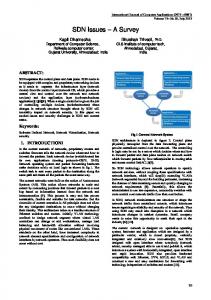
2. RELATED WORK Hardware description languages (HDLs) like VHDL or Verilog are widely used to model and simulate processors, but mainly with the goal of developing hardware. Using these models for instructionlevel processor simulation has a number of disadvantages. They cover hardware implementation details which are not needed for performance evaluation and software verification. Moreover, the description of detailed hardware structures has a significant impact on simulation speed [2]. Another problem is that the extraction of the instruction set is a highly complex, manual task and instruction set information, like e.g. assembly syntax cannot be obtained from HDL descriptions. The machine description language nML was developed at TU Berlin [3] and adopted in several projects [4]. While retargetable assemblers and disassemblers can be generated for some DSP processors, it is not possible to produce cycle-accurate simulators for pipelined processor architectures. These restrictions also apply to the approach of ISDL [5] which is very similar to nML. The approach based on the language EXPRESSION [6] incorporates particular mechanisms for the description of memory hierarchies and focuses on retargeting high level language compilers. However, no results are published that indicate the applicability for cycle-accurate simulation purposes. To summarize the review, none of the approaches above does support modeling of cycle/phase-accurate architectures including pipelines or the generation of very fast production quality tools. 3. SOFTWARE DEVELOPMENT TOOLS The LISA tool-suite is a set of development tools, which is automatically generated from LISA machine descriptions. It includes assembler, linker, simulation compiler and simulator as well as a graphical debugger frontend. Providing these tools, a complete software development environment is available which ranges from the assembly source file up to simulation within a comfortable graphical debugger frontend. Figure 1 shows the components of the LISA tool-suite. LISA Simulator and Simulation Compiler The LISA simulator utilizes the technique of compiled simulation for outstanding simulation performance [7]. Compiled simulators are application-specific simulators, which are generated out of the target application file by inserting a translation step before the simulation is run. The translation of the application is performed by a tool called simulation compiler.
$ $
ADSP2101 The Analog Devices ADSP2101 is a 16 bit fixedpoint DSP with 20 bit instruction-word width. The realization of the LISA model of the ADSP2101 at cycle accuracy took approx. 3 weeks.
Fig. 1.
������� �� �� �������� �������� ���� ����� �� �� ��!�#"
A major task in compiled processor simulation is to determine the temporal order of executed operations – in particular for pipelined architectures. The simulation compiler utilizes three scheduling principles to generate the most efficient simulator for the underlying architecture model: dynamic scheduling, static scheduling, and‘ instruction-based code translation. Principles and implementation aspects of these simulation techniques are discussed in [8]. LISA Assembler and Linker The LISA assembler translates meaningful text-based instructions into object code for the respective programmable architecture. Beside the processor specific instruction-set, the LISA assembler provides a set of pseudo-instructions to control the assembling process (directives). This concerns data initialization, reasonable separation of the program into sections, handling of symbolic identifiers for numeric values and branch addresses. The retargetability of the LISA assembler requires support for unrestricted instruction word-sizes and the handling of complex assembly syntax. The linking process is controlled by a linker command file which keeps a detailed model of the target memory environment and an assignment table of the module sections to their respective target memories. Graphical debugger frontend The LISA debugger frontend is a generic GUI for the generated LISA simulator. It visualizes the internal state of the simulation process. Both the C-source code and the disassembly of the application as well as all configured memories and (pipeline) registers are displayed. All contents can be changed in the frontend at runtime of the application. The simulation process can be controlled by stepping and running through the application and setting breakpoints. 4. CONSIDERED ARCHITECTURES To examine and analyze the modeling abilities of LISA as well as the feasibility of generating software development tools, four different architectures have been considered. The architectures were carefully chosen to cover a broad range of architectural characteristics and are widely used in the field of digital signal processing (DSP) and embedded systems. Moreover, the abstraction level of the models ranges from phase accuracy (TMS320C62x) to instruction-set accuracy (ARM7).
$
ARM7 The ARM7 core is a 32 bit micro-controller of Advanced RISC Machines Ltd. The realization of a LISA model of the ARM7 C at instruction-set accuracy took approx. two weeks.
$
TMS320C54x The Texas Instruments TMS320C54x is a high performance 16 bit fixed-point DSP with a five stage instruction pipeline. The realization of the model at cycle accuracy (including pipeline behavior) took approx. 8 weeks. TMS320C62x The Texas Instruments TMS320C62x is a general-purpose fixed-point DSP based on a very long instruction-word (VLIW) architecture containing an eleven stage pipeline. The realization of the model at phase accuracy (including pipeline behavior) took approx. 6 weeks. 5. ARCHITECTURAL CHARACTERISTICS
Every architecture has its characteristics particularly with regard to the instruction-set or the structure. However, even for complex architectures the high modeling efficiency of LISA allows to realize a model of the chosen architecture in a reasonable amount of time. This section focuses on the modeling of specific aspects for each presented architecture. 5.1. VLIW The C62x DSP of Texas Instruments is a VLIW architecture with 256 bit instruction word width. The instruction word is fetched as a whole from memory and then partitioned in eight micro instructions which are dispatched into the execution pipeline. For the modeling of word-sizes greater then the maximum word size of the simulating host, LISA provides a dedicated type bit which is parameterized by the resources bit-width. RESOURCE { ... unsigned bit[256] insn_register; ... }
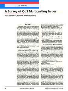
is an excerpt of the resource-declaration of the C62x LISA model showing the declaration of the instruction register. The bit data type in LISA contains a set of overloaded operators and can thus be used in the behavior code of the LISA model as any other Ctype can. For modeling of signed and unsigned operations on the processor resources, the bit data-type can be attributed with a signed or unsigned keyword. 5.2. Non-orthogonal Coding Fields In LISA, non-orthogonal coding is expressed by additional conditional statements that can be used to structure the processor model [7]. The purpose of these conditional statements is to express the coding dependencies between different operations. Following the syntax of programming languages, they have the form of IF-ELSE and SWITCH-CASE statements. Figure 2 displays the coding of an instruction word taken from the C62x LISA model. There are three instructions add, sub, and mul whose execution is also controlled by the coding field
Fig. 2.
%&� ����� �'�'��� � �!�� (�)�*��+� ����-,�����+�.�"
Decode, Fetch and Prefetch are thereby processor resources carrying the instruction words whereas Type1, Type2 and Type3 represent the three coding trees for the respective instruction type. The branching into the three coding trees is controlled by a SWITCH-CASE statement which is part of the LISA control structure. The selection of the appropriate coding root is based on an enumeration type with the effect that all coding trees are searched until the currently processed instruction word is identified. 5.4. Non-coherent coding elements
mode which selects between short and long operands and their specific arithmetic. However, the other instructions ld and sto use the mode field for a different purpose. LISA code for the add instruction in the C62x model is shown in example 1. Here, the IF-THEN-ELSE statement encloses two alternative sections with their respective behavioral description of the operation add. This formal representation lets the simulation compiler distinguish these two cases and generate specific simulation code. OPERATION add { DECLARE { REFERENCE mode; } IF (mode == short) { BEHAVIOR { dest_lo = src1_lo + src2_lo; } } ELSE { BEHAVIOR { dest_lo = src1_lo + src2_lo; carry = dest_lo >> 16; dest_lo &= 0xFFFF; dest_hi = src1_hi + src2_hi + carry; } } }
Example 1: Formal expression of non-orthogonality. 5.3. Multiple instruction words Frequently, architectures are employed which utilize instructions made up of multiple instruction words. The TMS320C54x DSP contains instructions that can be composed of either one, two or even three instruction words. The second/third instruction word mostly carries immediate values or operands but can also be part of the opcode of the instruction. The correlation between the different instruction types and the decoders is established in the coding-root. Example 2 shows the mapping of each instruction type described in the coding-root of the LISA description onto the respective coding tree.
OPERATION Decode IN pipe.DC { ENUM InsnType = Type1, Type2, Type3; SWITCH (InsnType) CASE Type1: CODING { Decode == Decode_16 } CASE Type2: CODING { (Decode == Decode_32) && (Fetch == Operand) } CASE Type3: CODING { (Decode == Decode_48) && (Fetch == Operand1) && (Prefetch == Operand2) } }
Example 2: Formal expression of multiple insn-words
Especially in low-power architectures an optimal usage of the instruction word is required. Here, coherent coding-fields are split into multiple pieces spread over the instruction word. In the ARM7 C, this is the case for the operand in ALU-instructions. OPERATION Data_Processing_ALU { CODING { 00b Operand2=[11..12] OpCode Setcond Src1 Dest Operand2=[0..10] } }
Example 3: Modeling non-coherent coding in LISA The coding of Operand2 is distributed over the coding of the operation Data Processing ALU. Example 3 shows how the merging of the coding tree is modeled in LISA. The distributed coding element is attributed with the position in the coding of the LISA operation the element is referring to. 5.5. Algebraic instruction syntax Sometimes, architectures programmed primarily in assembly use a C like assembly instruction syntax to ease programming. The Analog Devices ADSP2101 features such an algebraic programming syntax. This means that the instruction syntax is not fragmented into a mnemonic and a list of operands but formulated as an algebraic expression. An example for an algebraic instruction would be : ADD Y,X,Z
/�0
X=Y+Z
The LISA control-flow syntax can be used to express the syntax dependency on the coding of the instruction-word. Example 4 shows an excerpt of the model of the ADSP2101. Here, depending on the Opcode of the instruction word the respective syntax is chosen via the SWITCH-CASE control structure. OPERATION ALU_Instructions { GROUP Opcode = { ADD || SUB || AND }; CODING { 0011b Opcode } SWITCH(Opcode) CASE ADD: SYNTAX { Dest "=" Xop "+" Yop } CASE SUB: SYNTAX { Dest "=" Xop "-" Yop } CASE AND: SYNTAX { Dest "=" Xop "&" Yop } }
Example 4: Algebraic instruction syntax in LISA
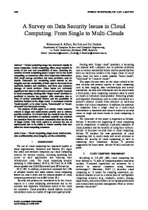
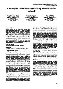
6. EFFICIENCY OF GENERATED TOOLS To evaluate the applicability and efficiency of the generated tools, we compared them to the commercially available tools provided by the semiconductor vendors. Measurements took place on a AMD Athlon system with a clock frequency of 800 MHz. The system is equipped with 256 MB of RAM and is part of the networking system. It runs under the operating system Linux, kernel version 2.2.14. Tool compilation was performed with GNU gcc, version 2.92. The generation of the complete tool-suite (simulator, assembler, linker and debugger frontend) takes, depending on the complexity of the considered model, between 12 sec (ARM7 C instructionset accurate) and 67 sec (C62x DSP phase accurate). 6.1. Performance of generated simulator Figures 3 and 4 show the speed of the generated simulators in instructions per second/cycles per second respectively. Simulation speed was quantified by running an application on the respective simulator and counting the number of prcocessed cycles. The simulated application on all architectures is an ADPCM G.721 (Adaptive Differential Pulse Code Modulation) coder/decoder.
Fig. 4.
1� ��D���E �� ��!�3.F4G� �H+I� 6KJML(N� (��+3JPO Q N
In case studies models were realized and tools successfully generated for the ARM7 C, the Analog Devices ADSP2101, the Texas Instruments C62x and the Texas Instruments C54x on instructionset/cycle/phase accuracy respectively. Due to the usage of the compiled simulation principle, the generated simulators run by one to two orders in magnitude faster than the vendor simulators. Moreover, the generated assembler and linker can compete well in speed with the vendor tools. Our future work will focus on modeling further real-life processor architectures. Another issue is the integration of software simulators into HW/SW co-simulation environments. Furthermore, the goal of the ongoing language design is to address VHDL-code synthesis for the control-path and the instruction decoder of the modeled architecture. 8. REFERENCES
Fig. 3.
1� ��2���� (�' �� �3.'45����+��(67�&8�9;:- ��+1�?A@�B�C�B
As expected, the compiled simulation technique applied by the generated LISA simulators outperforms the vendor simulators by one to two orders in magnitude. For the ARM7, ADSP2101 and the C54x, static scheduling was applied, which is the highest possible grade of prediction in compiled simulation. Considering an ARM7 C running at a frequency of 25 MHz, the software simulator running at 31 MIPS even outperforms the real hardware. This makes application development suitable before the actual silicon is at hand. Due to its superscalar instruction dispatching mechanism the simulator for the C62x DSP uses compiled simulation with dynamic scheduling. 6.2. Performance of generated assembler and linker The generated assembler and linker are not as time critical as the simulator is. It shall be mentioned though that the performance (i.e. the number of assembled/linked instructions per second) of the automatically generated tools is comparable to that of the vendor tools. 7. CONCLUSION In this paper, we presented a survey on modeling programmable architectures using the machine description language LISA.
RTS�UDV�WPX)Y�Y�Z�[>\�WM]A^�_�`ba cdc5[�e&Wgf�hjik^*l�cd^*i(hjmH[�a�c�no]pWPq-Y�r(st[ uwv5x V!\zy{q|a m'}!hjcdY~PY�Zm�shj h^�c v a cd
Hda�
�Y�^�sr!m�Y' \m�m� sFa Y7q-^(n Y�jZ^�dX#s^�
�sFa ``ba�djY~�V!X�\Ksm'}!hjY�m�!sY�Z�[ hjc Proceedings of the Design Automation Conference (DAC) [ AY�AsjYta�c!ZF'[d!5W!H�*y(�H([�Hdc!Y>StH� W R *Ub WA^tKZ^Hc�[ u ]Pa sFn(7a*sY* HV(^��¡7a*sY¢m�^�£Zhj`�!�a*hj^Hc5[ ¤hjc Proc. [�ofS�Hthe �¥ W ACM/IEEE Design Automation Conference (DAC) R Ub\�W¦�a !}�[q�W#¦!sY�Y�shjmF§(Z�[¨a�c�n3\�W©gcd^�jª[ u�« Y�cdY'sFa hj^Hc¬^� }da sFn(7a sY�`ba m'}!hc!YP`^(n!Y�ZK�s^�`hc!Z�sdm�hj^�c|ZY�Mn!Y�Zm�shj hj^�cdZ�[ ®hc Proc. of the IEEE Workshop on VLSI Signal Pro[GSt�H(W R ¥�UDcessing q�W�]Ma s^ ^�
![G!W�A^tKZ^�c5[ et al. [ u�« Y�cdY'sFa hj^Hc�^�Z^��¡7a*sY ^ ^�jZ�s^�`¯ s^ m�Y�ZZ^ s7n!Y�Zm�shj!hj^Hc!ZE^ s°}da sFn °a sY* *Z^��w7a*sY m�^(n!Y�Zhj
Hc�[ ±hjc Proc. of the Design Automation Conference [!H!c5W�St�k²(W (DAC) R ³*U « W ]MaHn lwhTr!ha cdcdhjZ�[kV�W ]Pa cd^�cd^![Ha�cdn�V�W*~PY�i�aHn!a�Z�[ uwx V(~ v¨´ \c hjc!Z�sdm�hj^HcZY'µn Y�Zm�shj!hj^�c�a cd
��a�
�Y�^�s¨sY�Fa s
�Y�Fa�!hjhT¡r [ hjc Proc. of the Design Automation Conference (DAC) [)Hdc�W S�HH²(W R ¶ Ub\�W·]Ma�a�`pdh[±XW « sdc�[±Y' al. [ u�¸#¹ X# ¸ VdV x M ´ \ a cd
Hda�
�Yº�^�sa*sm'}!hTY�m�!sYY�» !^ sFa hj^Hc¢} s^Hd
�}¢m�^H`> !hjY's' Zhj`�!�a*^�s)sY'Fa s
HY'Fa�dhjjhTwr [ ghjc Proc. of the Conference [kq|a stW�S�H� W in Europe (DATE) R ²*UDon V�W°Design, X)Y�Y�Z�[\&Automation W]M^ _�`ba�cd&c�[7Test a c�n¼ ]&W°q-Y'r st[ u AY'Fa s
HY'hc!
3^� m�^H`dhjjYtn>Zhj`�!a ^�sZ#E^ s7n h
�hTFa��Zhj
Hcda�� s^ m�Y�ZZ^�sZµdZhjcd
�a `ba m'}!hjcdYKn!Y�Zm�shj!hj^Hca�c!
Hda�
HY�[ phjc Proc. of the Conference [kq|a stW ½H½�½ W R Uon e&WbDesign, f�¾ hiH^ lwcd^*Automation i(hFm< ¿ a�cdnÀ]&&WTest q-Y�r(inst[ Europe hjYtnÀ]AÁÀ HV(ÁÂm�^ u µ^H`!(DATE) Zhj`pda hj^Hc�[ Mhjc Proc. of the DAC 1996 – Las Vegas [ d�Wt¶�H½*y ¶�k³ [�H!cdY>St�H¶(W