The first commercially available DSP processor, the NEC 7720, had a .... software synthesis tool takes DSP or a communication algorithm specified in a high-level language as ..... C is a set of system configurations (computational structures) ...
A survey on Reconfigurable Computing for Signal Processing Applications Anne Pratoomtong
Abstract A Signal processing system has to meet real-time requirements and provide very large throughput in the magnitude of Giga-operations per second. These real time requirements put pressure on the hardware running signal-processing applications. Therefore, custom hardware such as ASIC, dedicated DSP processors or scalable parallel hardware architecture is frequently used as an implementation mechanism for many DSP applications to achieve high performance. Configurable computing has emerged in the past decade as a method for dynamically adapting computer algorithms, architecture, and hardware to track the variations in the computation and its environment. Most of the signals processing applications have a welldefined structure with a lot of inherent parallelism, which can be represented by a signal flow graph. The signal-processing algorithm is based on the availability of a priori information about the signal source and the noise in the environment. The performance of the implemented system largely depends on the environmental conditions as well as addition factors, such as the computing resources available. These major characteristics of signal processing applications make the reconfigurable and structure adaptive as an attractive approach to design a signal processing system.
This project surveys academic research in reconfigurable and structure adaptive computing for DSP systems in the past fifteen years. The main focus of this project is to survey design methodology and tools for dynamic runtime reconfigurable systems. A definition and history of reconfigurable computing for DSP, various design tools and methodologies for reconfigurable and structure adaptive signal processing systems, and some applications of reconfigurable and structure adaptive computing in high performance signal processing system will be presented.
1
Introduction Digital signal processing applications require high computational performance due to their real-time characteristics. There are many implementation media available for signal processing. These implementations vary in terms of programmability from fixed-functionality hardware like ASICS to fully programmable like general-purpose processors. The emergence of the new architecture, which offers the same computational attributes as fixed-functionality architectures in a package that can be customized in the field, is driven by a need for real-time performance within the given operational parameters of a target system and a need to adapt to changing data sets, computing conditions, and execution environments of DSP applications. Performance
Cost
Power
Flexibility
Programmability
General-purpose Processor
Low
Low
Medium
High
High
Programmable DSP
Medium
Medium
Medium
Medium
High
Reconfigurable Hardware
Medium
Medium
High
High
Medium
ASIC
High
High
Low
Low
Low
Table1: DSP Implementation comparison Since the early 1960’s, three themes have driven the development of DSP implementations: data parallelism, application-specific specialization, and functional flexibility. The choice of DSP system implementation requires a tradeoff between these system goals. As a result, a sizable number of specialized hardware and software methodologies have been developed for DSP such as associative processing, bitserial processing, on-line arithmetic, and systolic processing. As shown in Table 1, various cost metrics have been developed to compare the quality of different DSP implementations. Performance has frequently been the most critical system requirement since DSP systems often have demanding real-time constraints, but over time cost has become more significant as DSP has migrated from predominantly military and scientific applications into numerous low-cost consumer applications. In recent years, power consumption has become a very important measure as DSP techniques have been widely applied in portable, battery-operated systems such as cell-phones, CD players, and laptops. Finally, flexibility has emerged as one of the key differentiators in DSP implementations since it
2
allows changes to the functionality at various points in the design life cycle. These cost tradeoffs have resulted in four primary implementation options including application-specific integrated circuits (ASICs), programmable digital signal processors (PDSPs), general-purpose microprocessors, and reconfigurable logic. Each implementation option presents different tradeoffs in terms of performance, cost, power and flexibility.
History of Reconfigurable Computing Reconfigurable computing became widely used when Xilinx Corporation introduced the first commercial SRAM-based FPGAs in 1986. These reprogrammable devices contain a collection of fine-grained programmable logic blocks interconnected via wires and programmable switches. Logic functionality for each block is specified via a small programmable memory, called a lookup table, driven by a limited number of inputs (typically at most six), which generates a single Boolean output. Additionally, each logic block contains one or more flip-flops for fine-grained storage. While early FPGA architectures contained small numbers of logic blocks, new device families have quickly grown to capacities of tens of thousands of lookup tables containing million of gates of logic. Much of the recent interest in reconfigurable computing has been spurred by the development and maturation of field-programmable gate arrays. The recent development of systems based on FPGAs has been greatly enhanced by an exponential growth rate in the gate capacity of reconfigurable devices and improved device performance due to shrinking die sizes and enhanced fabrication techniques. The gate capacity of FPGAs from Xilinx Corporation has roughly followed Moore's Law over the past decade enabling complex structures such as multi-tap filters and small RISC processors to be implemented directly in a single FPGA chip. Furthermore, over this same time period, the performance of these devices has also improved exponentially. Given the programmable nature of reconfigurable devices, the performance penalty of a circuit implemented in reprogrammable technology versus a direct ASIC implementation is generally on the order of a factor of five to ten. Fully stand-alone programmable digital signal processors appeared in the early 1980s. There were many vendors such as NEC, TI, Intel, Motorola, AT&T, IBM, and Analog Device with competing digital signal processors. The first commercially available DSP processor, the NEC 7720, had a hardware multiplier, and
3
a Harvard architecture, which supported concurrent memory access to data memory and program memory. Intel introduced the 2920 with a unique feature that included A/D and D/A converters on-chip. However, it had no hardware multiplier. In addition, it was hard to get parameters into the chip because it lacked a digital interface. Texas Instruments introduced the TMS32010 in 1982. The 32010 had a hardware multiplier and Harvard architecture with separate on-chip buses for data memo ry and program memory. This was the first programmable DSP to support executing instructions from off-chip program RAM without any performance penalty. This feature brought PDSPs closer to the microprocessor / microcontroller programming model.
Reconfigurable computing for DSP Research Directions Reconfigurable computing comes in many forms with a different reconfigurable granularity. FPGAs provide a fine-grained reconfigurable functionality at gate-level. Programmable DSP supports high-level software dynamic reconfiguration. Many reconfigurable architectures are built to provide a multi-level reconfigurable granularity (E.g. general purpose microprocessor, PDSP, reconfigurable dataflow, FPGAs). These systems composed of a wide variety of macro modules such as core processors, PDSPs, programmable logic, FPGAs, embedded memory, ASICs, and custom modules connected via reconfigurable communication network. Most DSP systems have a need for configurability of adaptability under a variety of constraints. These constraints include environmental factors such as changes in statistics of signals and noise, weather, transmission rates, and communication standards.
Reconfigurable computing for DSP can be categorized as follows. (1) Pre-Runtime Reconfigurable – In the context of reconfigurable computing, this term indicates that a computing system or device logic functionality and interconnect can be customized to suit a specific application through post-fabrication, user-defined programming. Since systems of this type have an ability to adapt to the changing of the applications, the hardware platforms using this type of systems are mostly in the form of System-on-Chip which contain a mixed variety of macro module with different characteristics (Performance, cost, power, flexibility, programmability)
4
connected via reconfigurable communication network. The adaptation occurs upon the change of application. That is, given an application, the synthesis tool explores the possible design space and chooses the appropriate configuration to achieve high-performance or low power. The hardware platform is then reconfigured to the configuration result from the synthesis tool. The devices with Pre-runtime reconfigurable capability are important in the face of changing standards, communication protocols, computing algorithms, or applications. There are many projects that involve an implementation of the reconfigurable architecture in this type such as Splash II [Splash], PAM [PAM], Prism I [Prism], Garp [Garp], Pleiades [Pleiades]
(2) Run-time (or Dynamically) Reconfigurable (RTR) – System logic and/or interconnect functionality can be modified during application execution. This modification may be either datadriven or statically scheduled. DSP applications whose performance and functionality depend on run-time factors such as time-varying noise, runtime environment, computation resources available, or time-varying data set require this type of reconfigurable computing. There are two major research directions for run-time reconfigurable (RTR) systems, FPGAs base RTR and Structure Adaptive RTR. For FPGA base RTR, a software library or driver is developed to handle reconfiguration requests. Existing research on FPGAs base RTR are JHDL [JHDL], RTR system with low reconfiguration overhead [Heron], Novel FPGA architectures with context switching or configuration data caching [Scalera], Pre RTR [PreRTR], Partial reconfiguration [Shirazi], and Bit stream compression technique [ Hauck]. Structure Adaptive RTR system was developed in the late 1980s by the ISIS research group at the Vanderbilt University [Vanderbilt]. The next section provides information of some of these reconfigurable computing systems in more detail.
Reconfigurable DSP systems and their applications (1) Pre-Runtime Reconfigurable (1.1)
Splash II [Splash]
Splash II is a multi-FPGA parallel computer which uses orchestrated systolic communication to perform inter-FPGA data transfer. Each of the Splash II boards contains 16 Xilinx XC4000 series
5
FPGA processors, each with associated SRAM, inter-FPGA crossbars for multi-hop data transfer and broadcast. Mapping software for the system typically involves users writing VHDL for individual systolic processors that meet size and performance constraints and then using high-level scheduling software to ensure that system-wide communication is synchronized. For applications with SIMD characteristics, a complier [Gokhale] has been created to automatically partition processing across FPGAs and to synchronize interfaces to local SRAMs. Real-time image processing typically requires specialized data paths and pipelining, which can be implemented in FPGA logic. Therefore, numerous DSP applications have been mapped to Splash II, including audio and video algorithm implementations. In [Athanas], [Abbott], and [Ratha], a set of image processing tasks such as Gaussian pyramid-based image compression, image filtering with 1D and 2D transforms, image conversion using DFT operations, and 2D DCT algorithms are mapped to the Splash II platform. The distributed construction of a stand-alone Splash II system containing numerous physical I/O ports was shown to be particularly useful in achieving high data rates. Since Splash II is particularly effective in implementing systolic versions of algorithms that require repetitive tasks with data shifted in a linear array, image data can quickly be propagated in a processing pipeline. The targeted image processing applications are generally implemented as block-based systolic computations with each FPGA operating as a systolic processor and groups of FPGAs performing specific tasks. Another important DSP application that has been applied to Splash II is target recognition [Rencher]. To support this application, images are broken into columns and compared to pre-computed templates stored in local memory along with pipelined video data. A near-neighbor communication is used with Splash II to compare pass-through pixels with stored templates in the form of partial sums. After an image is broken into pieces, the Splash II implementation performs secondlevel detection by roughly identifying sections of sub-images that conform to objects through the use of templates. In general, the use of FPGAs provides a unique opportunity to quickly adapt target recognition to new algorithms, something not possible with ASICs.
6
(1.2)
PAM [PAM]
Programmable Active Memory DECPeRLe-1 systems (PAM) contain arrangements of FPGA processors in a two-dimensional mesh with memory devices aligned along the array perimeter. PAMs were designed to create the architectural appearance of a functional memory for a host microprocessor and the PAM programming environment reflects this. From a programming standpoint the multiFPGA PAM can be accessed like a memory through an interface FPGA with written values treated as inputs and read values used as results. Designs are generally targeted to PAMs through handcrafting of design sub-tasks, each appropriately sized to fit on an FPGA. The PAM array and its successor, the Pamette [Pamette], are interfaced to a host workstation through a back plane bus. There are many projects which implement real time applications such as image processing, video processing, audio and speech processing, and communication coding, on PAM systems. PAM was the first platform used in video applications. A PAM system programmed to perform stereo vision was applied to applications requiring three-dimensional elevation maps such as those needed for planetary exploration. A stereo matching algorithm was implemented that was shown to be substantially faster than programmable DSP-based approaches. This implementation employed dynamic reconfiguration by requiring the reconfiguration of programmable hardware between three distinct processing tasks at run time. A commercial version of PAM, the turbochannel-based Pamette, was used for image processing applications. In [87], Pamette is interfaced to a CCD camera and a liquid crystal polarizing filter is used to perform solar polarimetry. The activity of this application is effectively synchronized with software on an Alpha workstation. While audio processing typically requires less bandwidth than video and image processing, audio applications can benefit from datapath specialization and pipelining. To illustrate this point, a sound synthesizer was implemented using the multi-FPGA PAM system [PAM] producing real-time audio of 256 different voices at up to 44.1 kHz. Primarily designed for the use of additive synthesis techniques based on lookup tables, this implementation included features to allow frequency modulation synthesis and/or nonlinear distortion and was also used as a sampling machine. The physical implementation of PAM as a stand-alone processing system facilitated interfacing to tape recorders and audio amplifiers. The system setup was shown to be an order-of-magnitude faster than a contemporary off-the-shelf DSP. The PAM project was also involved
7
in communication application. In [PAM], the on-board PAM-system RAM is used to trace through 214 possible states of a Viterbi encoder allowing for the computation of 4 states per clock cycle. The flexibility of the system allowed for quick evaluation of new encoding algorithms
(1.3)
Prism I [Prism]
The Prism I project is the first reconfigurable system which tightly coupled an off-the-shelf processor with an FPGA coprocessor. This project explored the possibility of augmenting the instruction set of a processor with special-purpose subroutines that could be executed by an attached FPGA coprocessor in place of numerous processor instructions. For these instructions the microprocessor would stall for several cycles while the FPGA -based coprocessor completed execution.
(1.4)
Garp [Garp]
As chip integration levels have increased, interest in tightly coupling both processor and reconfigurable resources at multiple architectural levels has grown. As a result, Single-chip architectures such as Garp [Garp] allow interfacing between processors and reconfigurable resources both through coprocessor interfaces and through a shared data cache. The reconfigurable hardware attached to the main MIPS processor functions as a coprocessor. Explicit processor move instructions give the main processor complete control over the loading and execution of the coprocessor’s configuration. Grap uses a simple and straightforward synthesis approach. It uses the complier to extract a potential loop that can be executed using the coprocessor then constructs a DFG to represent the loop body and performs a direct mapping of nodes in the DFG to the modules on the coprocessor. This results in a faster compilation speed compares to the traditional hardware synthesis technique. The design goal of Garp is to accelerate the loops in a general-purpose program using the coprocessor. However, the simulation results shown in [GARP] demonstrated that Garp yielded a good performance when executing some signal processing algorithms that have regular loop structure. This is due to the performance benefit from the coprocessor outweighs the overhead (i.e. configuration load cost, data transfer between coprocessor and main processor) when executing the loop repeatedly many times.
8
(1.5)
Pleiades [Pleiades] Pleiades architecture consists of a programmable microprocessor and heterogeneous
computing elements referred as satellites. The architecture template fixes the communication primitives between the microprocessor and satellites and between each satellite. For each algorithm domain (e.g. communication, speech encoding, video coding), architecture can be created. The software synthesis tool takes DSP or a communication algorithm specified in a high-level language as input. Then base on a power-delay constraint model, the synthesis tool partitions the application into 2 parts – all costly kernels are mapped to hardware which will be implemented by satellites while the rest of the algorithm remains as high-level language and will be executed by the core processor. After all the satellites are assigned, the synthesis tool chooses a good reconfigurable interconnect architecture. The satellites and reconfigurable interconnect are then configured according to the result from the synthesis tool. In [Pleiades], the case study architecture, which consists of embedded ARM8 core, MAC, ALU, memory, address generator, and FPGA, are implemented in 0.25 um technology. The tested algorithm is the multiuse detection LMS filter [Zhang] that provides symbol rate at 1.67 MHz for a spreading factor of 15. The result showed that the algorithm which is synthesized and mapped to Pleiades architecture consumes 20 times less energy than the algorithm that runs on a conventional ARM processor with the same performance.
(2) Run-time (or Dynamically) Reconfigurable (2.1)
FPGA Base RTR
The adaptation is done at the hardware level using the FPGA base system. Changing the hardware structure is a time consuming process. Therefore, in order to make the DSP system that is implemented in a FPGA platform able to reconfigure at runtime, the methodology of fast and low overhead reconfiguration needs to be implemented. (2.1.1) Partial Reconfiguration [Shirazi] By matching the commo n component between two successive circuit configurations, the partial reconfiguration is able to reduce the reconfiguration time. Even though the partial
9
reconfiguration design has higher reconfiguration time than the single cycle reconfigurations design, by allowing the hardware to be partially reconfigured during runtime, the area of the design reduces and operation speed of the design increases compared to those designs with single cycle reconfiguration time. This is because the design that has single cycle reconfiguration time requires redundant hardware so that the reconfiguration is triggered by changing of the control signal without any changing of the hardware structure and therefore, consumes more area than the partial reconfiguration design. Furthermore, the extra hardware tends to increase the complexity of the design, which in turn, limits the operation speed. Even though the partial reconfiguration design takes multiple reconfiguration cycles, as long as the circuits are not reconfigured too often, this kind of design can be beneficial. The reconfiguration time of the partial reconfiguration design is relatively low compared to the number of clock cycles the design would have to run in data processing mode to justify run-time reconfiguration overhead. In [Shirazi], Adder/Subtractor , Pattern Mattcher, 1-D Image Filter are implemented using partial reconfiguration design and single-cycle reconfiguration design. The results show that the partial reconfiguration design results in a smaller area, higher operation speed, and higher reconfiguration cycle for all three applications. For the partial reconfiguration approach, an adder is changed to a subtractor by reconfigured one xor gate in the adder circuit to xnor gate while for the single cycle reconfiguration approach combines an adder with a subtractor by adding circuitry to calculate the 2’s complement of one of the inputs based on a control signal. Therefore, the reconfigure between adder and subtractor can be done by simply changing the control signal, which takes only one cycle. For a 32-bit pattern matcher, the partial reconfiguration design takes up only 64 FPGA cells, while a design including an additional shift register for storing the pattern and an additional row of comparator of single cycle reconfiguration design takes up twice as much space. By adding the register and comparator to the repeating cell of the pattern matcher, it also increases the propagation delay by 52%. The image filter has a similar pattern of results, i.e. the partial reconfiguration design is smaller and faster than the single cycle reconfiguration design.
10
(2.1.2) RTR system with low reconfiguration overhead [Heron] [Heron] purposed an RTR system with low reconfiguration times. The system was developed to specifically exploit the use of partial reconfiguration at the algorithm/architecture level and throughout the FPGA circuit synthesis design flow, in order to minimize reconfiguration times. The software interface called Virtual Hardware Handler (VHH) was developed to handle the HW/SW reconfiguration interface. The application source code is parsed at compile time to extract the hardware functions and then all the possible reconfigurations of functions on the hardware are recorded in the form of a directed graph called Reconfiguration State Graph (RSG). RSG is constructed such that the transition time between any two different hardware functionalities is optimized. Therefore, the hardware is transformed according to the state in RSG when the hardware functionality needs to be changed. The reconfiguration between three arithmetic functions, Multiplication, division, and square root is performed using the RSG. The results show that although the RSG may increase the reconfiguration stage, there’s still a gain in reduction of reconfiguration time. A FIR filter was implemented using only one multiplier-accumulate (MAC) processor to show the performance of the proposed method. Three different scenarios were investigated: static implementation where a single tap is used and coefficients are stored in internal registers, and dynamic implementation where fixed tap is used using both full reconfiguration and the proposed partial configuration technique. The dynamic designs allow the MAC to be implemented using a fixed coefficient, which results in a superior speed and smaller area. The results of the comparison which shows the data processed per second against the data block size that was processed between reconfigurations is presented. The static implementation computes results at a constant rate while in dynamic implementation; the data rate depends on how much data is processed using the existing configuration. The partial reconfiguration technique yields a higher data rate than the fully reconfiguration technique with the same data block size.
11
(2.1.3) JHDL [JHDL] JHDL is a java based HDL design environment that can be used to design runtime reconfigurable systems. JHDL permits users to describe hardware structures as objects and automatically configures hardware circuits into FPGAs when these hardware-object constructors are invoked. This technique has two major limitations: (1) it does not have the ability to partially reconfigure as in the previous two techniques. (2) It only maps the algorithm to a single FPGA platform rather than a more complex platform with multiple reconfigurable hardwares. JHDL has an automatic target recognition (ATR) algorithm as a case study. The algorithm performs binary thresholding of radar images, where the threshold values are locally computed at each position in the image. After the image is thresholded, it is correlated to template images that describe both the foreground and background feature of the target. The target is present when both correlations are high. Therefore, the ATR problem requires two circuits: one to compute the adaptive threshold values, and one to compute the correlation. When mapping this algorithm to a single FPGA chip, the device has to be context switched back and forth between the Shapesum and correlator since the device is only big enough to contain one circuit at a time.
(2.2)
Structure Adaptive RTR
The DSP system should be able to perform well regardless of the execution environment, which mostly is time varying and cannot be modeled, controlled or stabilized in the design time. For example, in turbine engine testing, the deterioration of sensors is unavoidable. To design a single robust DSP algorithm, which is able to tolerate any possible changes in the environment, is not practical since the price of robustness is usually decreased performance or increased complexity. Therefore, a better approach is to design a system which is able to adapt to the changing environment. A Structure adaptive digital signal processing system can modify its own structure while it is running according to the run time environment. The development of a structure adaptive system can be partitioned into two phases: self-adaptive software, and system-level synthesis
12
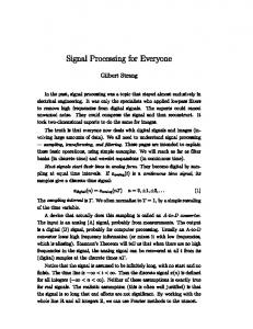
(2.2.1) Self-adaptive software [Multigraph] and [Sztipanovits] Digital signal processing system can modify its own structure (i.e. the composition of the signal flow) while it is running. The early project of the runtime reconfigurable system developed in the University of Vanderbilt using a software synthesis tool called ModelIntegrated Computing (MIC). The real-time application is implemented and executed using MIC. MIC is a graph-based computational model, which provides dynamic scheduling, multiprocessor programming capabilities, model-based approach system design, and graphic editor. The architecture developed for MIC is the Multigraph architecture (MGA), which has four main components of programming environment for DSP application as shown in figure 1.
Figure1: The relationship between model editing, models, model interpretation and execution. The model editing environment [MEE] supports the construction of a DSP model. The model Editing Environment has multiple modeling aspects including the signal flow model, the hardware architecture model and the resource constraint model, which are necessary for generating an executable application. The Model Interpreter performs the mapping between the DSP Models and the Control Graph, i.e. it maps the signal flow models into an executable model.
13
The control graph is an intermediate level of abstraction between the representation and execution. The runtime support for the Multigraph Computational Model is the Multigraph Kernel (MGK). MGK supports the creation of data flowgraphs and their execution. The kernel schedules the computational blocks as dictated by the control graph topology and the availability of data and/or request. The MGK has been interfaced to several computing platforms such as UNIX-based distributed systems, IBM-PC/DOS systems, ACE parallel workstations of IBM T.J. Watson Research Center, and stand-alone implementation of transputer network. More detail can be found in [Multigraph] and [Sztipanovits]. The signal extraction system and sonar signal processing [SASSonar] are applications which were implemented using this technique. The Signal extraction system receives data consisting of real sinusoids in additive broad-band noise, then identifies the sinusoids and removes the noise. The system also produces a plot of the sinusoidal signal and noise spectrum. The type and the order of the filter component in the signal extraction system can be reconfigured at run time depending on the execution environment such as noise characteristic, cut-off frequency. In sonar signal processing, the direction-of-arrival (DOA) algorithm is implemented using two techniques: Beam forming by way of a Spatial Transform and MUSIC estimate. Beamformer used an array of sensors to sample the arriving signals and typically, linearly combines the spatially sampled time series from each sensor in much the same manner that an FIR filter linearly combines temporally sampled data. In a SONAR application, tradeoffs between the two approaches cause the optimum choice of spatial transform or MUSIC to depend on both the current tracking situation and computer resources. The spatial transform is computationally faster than MUSIC estimate. However, spatial transform is a low resolution technique. The MUSIC estimate is a high resolution technique and it rarely gives false peaks. Generally, the spatial transform is used to search in a larger area with low resolution, and consider the peaks returned as locations of possible sources while MUSIC is used to search in a small area around those possible sources. Since MUSIC rarely gives false peaks, using MUSIC around possible sources will either confirm or reject these sources. The MUSIC and Spatial algorithms are implemented as an object whose parameters (e.g. optimum size, search range, can be adjusted). The controller controls and
14
coordinates the searches, managing the number of copies of spatial transform and music computation, and using predefined rules to decide the number of modules of each kind that can exist and run in parallel. (2.2.2) System-level synthesis [Neema] The system-level synthesis tool extend the capability of the Self-adaptive software describe in part 2.2.1. It defines a concept of system models and uses Model-Integrated Computing (MIC) as a synthesis design environment. The hardware platform is a part of system model and is chosen by the designer rather than a fixed predefine general-purpose commercial product as a hardware platform using in Self-adaptive software. Therefore, a wide range of application can be synthesized using this tool. The hardware platform is more like the hardware in Pre-runtime reconfigurable system where the platform consists of multiple computing modules. The design flow is to first construct system models of all possible aspect of adaptive computing (MSAC). Then perform synthesis based on the system mo dels to map the application into an execution platform. The adaptation of this system is driven by many factors but mostly by the unpredictable condition such as noise, executions environmental and occurs as a mode transition of the running application during run time. The following block diagram shows the design flow of the system level synthesis tool.
Figure 2: System level synthesis tool design flow Multi-model Structurally Adaptive Computing (MSAC) Systems MSAC compose of four sub-model (1) The operational behavior
15
The requirement for this model is that the operational space of the system is bounded and can be characterized into finite, discrete modes of operation. The adaptation occurs as a mode transition, which triggered by the execution environment, and controlled by the adaptation policies, which expressed as a mode transition rules. The modes of operation, transitions, and transition rules constitute the operational behavior. The operational behavior can be modeled using a directed graph called mode transition graph, which is shown in figure 3.
Figure3: Mode transition Graph The nodes of the graph represent modes of operation of the system, and the edges of the graph represent transitions. Edges are labeled with trigger conditions, which represented by a Boolean expression of the event. Events may occur asynchronously, and multiple events may occur simultaneously. The operational behavior of the system is deterministic i.e. at any time; no more than one transition is enabled simultaneously. The operational semantics may be modeled with the Finite State Machine (FSM) representation, which describes behavior in terms of states, transitions and events. When the number of modes and transitions are large, an extension of FSM representation [Harel], hierarchical FSM or concurrency FSM, is used.
(2) Execution Resources The computations are implemented as a set of computational components concurrently executing over a network of heterogeneous processing elements ranging from processors (RISC/DSP) to configurable hardware (FPGA), and communicating via signals or dataflow. The network of processing elements constitutes the execution resource set of the system. The resource network can be described with a directed graph called resource network graph shown in figure4. Nodes of
16
this graph represent the resources, while edges represent a physical communication channel between the resources.
Figure4: Resource Network Graph (3) Computational structure per mode of operation The computational structure consists of the set of computational components, the communication topology between the components, and the resource allocation. System configuration refers to the computational structure of the system, and the reconfiguration results in transitioning from a mode of operation to another which involves changing the computational structure of the system. The semantics of the computational structure can be described with an attributed directed graph know as process graph shown in figure5.
Figure5: Process Graph Nodes of this graph are computational processes, and edges represent communication (data flow) between processes. The processes operate continuously and concurrently transforming infinite sequence of input data to infinite sequence of output data. The processes communicate via exchange of data tokens. The communication is asynchronous and the tokens are buffered in FIFO queue. The processes in the process graph are distributed and executed over the set of resources.
17
Processes can be implemented as hardware or software functions. The processes implemented as software functions are scheduled to execute on a sequential processor by a runtime infrastructure. Processes are scheduled for execution when all the inputs to the process are available. And execution of the process consumes data tokens on the inputs and produces data tokens on the outputs.
(4) Constraints The functional requirements in each mode of operation define the signal/image processing computations that the system has to perform, and the performance requirements specify the constraints that the computations in a given mode must satisfy. Constraints play two important roles, establish linkages and describe interactions between the elements of the different aspects of an MSAC system (i.e. modes of operation, computation processes, and resources), and express restrictions over the composite properties of a computational structure. Object Constraints Language (OCL) is used to express the constraints [OCL].
MSAC model The MSAC model is constructed from the 4 sub-models describe above. Adaptive computing system can be represented by components in MSAC model as follow. D = {M, E, T, TC, m0 , R, C, MC}
(1)
Where D denotes an adaptive computing system M is a finite set of modes of operation E is a finite set of events T ⊆ M × M is the set of transitions TC: EP × T→ {true, false} denotes the trigger conditions on transitions; EP is the power set of E m0 ∈ M is the initial mode of operation R is a set of resources (processing elements) available for system execution C is a set of system configurations (computational structures)
18
MC: M→C is the mapping function that associates each node of operation with a configuration Note that M, E, T, TC, and m0 are parameters, which describe the operational behavior while R is a parameter in the resource execution model. Design space exploration The objective of design space exploration for system synthesis is to find a single design, or a set of designs from the design space that satisfies the system constraints and maximizes (minimizes) an objective (cost) function. The symbolic constraint satisfaction method and design space exploration tool were developed for pruning and exploration of large constraint based design space.
Adaptive Missile Automatic Target Recognition (AMATR) system This method is used to synthesis the military-based application due to its high flexibility. An embedded, real-time, Adaptive Missile Automatic Target Recognition (AMATR) system was chosen as a case study. The core of the AMATR system is an Automatic Target Recognition (ATR). ATR is an image processing algorithm for classification of target objects in a input image. The core processing of the algorithm is based on correlation filtering. The input image is correlated with template filter images corresponding to different target classes. The input image are further processed and classified by using a Distance Classifier Correlation Filtering (DCCF) algorithm when the input image corresponds to target objects. The ATR is a computationally intensive algorithm with an estimated throughput of 10-15 GFLOPS. Moreover, the system is embedded within a missile, tightly coupled with a closed-loop tracking and guidance system, imposes a wide range of operational and physical constraints on the AMATR system. There are real-time constraint due to the close coupling with the physical closed-loop guidance system, physical constraints due to the limited room available for electronics in the missile, and power constraints due to short battery life and limited heat dissipation capacity. In an operation lifecycle, the missile can undergo a large number of different modes of operations. These different modes of operation have different computational requirements, both in terms of functionality as well as performance and power. For example, the computation in target acquisition modes is throughput
19
critical since a sensor image with many different potential targets has to be scanned and annotated with potential target identities, priorities and locations while the computation in tracking modes is latency critical since an image with a single or a few targets is scanned primarily for determining the location changes of the locked target, to drive the closed loop tracking and guidance system. The power has to be managed over the operation life cycle i.e. power is tightly budget prior to missile launch when there is limited heat dissipation capacity and early on in the operational lifecycle when the battery has to be conserved while when closer to the aim-point, power budgeting is not critical. The AMATR system is modeled using MASC model as follow. -
Operational behavior: This model is captured with modes, transitions, and events. For example, the missile changes its mode from tracking mode to target acquisition mode when it lost the target.
-
Computation structure: Defining the computational structures for implementing the functional requirements of the different modes of operation. There are three forms of alternatives when modeling the computational structure of the AMATR system: (1) Functional alternatives: The different modes in ATR system have different functionality e.g. in short-range and aim-point tracking modes, a single target is being tracked. In longrange and mid-range acquisition modes, multiple targets are sought. However, its interfaces to the seeker and the tracking and guidance subsystem remain the same. (2) Algorithm alternatives: The ATR algorithm is correlation based. The image correlation can be performed using either spatial domain correlation of spectral domain correlation. Spatial domain correlation is computationally more expensive then spectral domain correlation but has smaller latency. (3) Implementation alternative: Many algorithms in the AMATR system such as, Cross-Correlation, FFT, IFFT, Matrix Multiplication, Peakto-Surface-Ratio calculation, etc. can be implemented as floating-point software subroutine, or a fixed-point software subroutine, or a digital circuit. The configuration space is composed in this manner by capturing all functional algorithm, and implementation alternatives. The selection of appropriate configuration for the different
20
modes of operation is done based on the design constraints in the design space exploration process. -
Execution Resource: To define the target platform for execution, the hardware-processing engineers capture the architectural details in the resource models, concurrently with the definition of the behavioral and comp utational structure models. The resource model of AMATR consists of 2 DSP processors, 1 RISC processor, and 1 FPGA, and 1 A/D for image acquisition.
-
Constraints: Constraints are specified both to express the design correctness criteria, as well as to help guide the constraint based design space exploration. All the constraints expressed while modeling the system may not be enforced. The user driving the interactive design space exploration determines the set of constraints to apply. All the four forms of constraints (compositional, resource, performance, operational) are used extensively in the AMATR system.
After the MASC model is constructed, the constraint based design space exploration is applied. The constraints are iteratively applied to reduce the system design space. Subsequent to the symbolic constraint satisfaction based design space exploration, the designer can continue with the exploration of the remaining design space using performance simulation and multiple fine-grained simulations. Typically, the design space exploration requires several iterations. Constraints have to be modified and refined to arrive at the desired solution. The final outcome o the design space exploration is a few design configurations that can be tested and implemented.
Discussion and future trend of runtime-reconfigurable system for DSP [Shirazi] claims that the partial reconfiguration is beneficial in terms of area and operating speed compared to those designs with single cycle reconfiguration time. However, [Martinez] shows that for real time applications such as high performance front-end radar signal processing, the slow reconfiguration time is unacceptable since the filter would be inactive during the reconfiguration. And even though the partial reconfiguration technique can be used so that one filter is active while the other filter is reconfigured in the same chip, it requires that the filter response must be known before hand which is not applicable for most
21
applications. Therefore, even though the FPGA has an ability to be reconfigured in-system, it is not suitable to use for run time reconfiguration design. [JHDL] maps the automatic target recognition (ATR) algorithm to a single FPGA chip. As a result, the device has to be context switched back and forth between the Shapesum and correlator since the device is only big enough to contain one circuit at a time. Therefore, the need of RTR comes in. However, if the application is mapped into a target architecture that contains multiple reconfigurable hardwares e.g. [Rencher] mapped ATR application into the SPLASH-II board which contains 16 FPGA boards with crossbar interconnection, the need of reconfiguration is gone since the Shapesum and correlator circuit can be mapped to two different FPGAs and thus the implementation of this system becomes a pre-runtime configurable system. The performance factor for the 2 choices depends on communication speed VS reconfigurable overhead, area, cost and power constraint. In general, the single hardware implementation leads to a more power-area effective system. There are some difference between the pre-run time reconfigurable systems and the run time reconfigurable system. The major difference is the factor which triggers the adaptation. The adaptation of the pre-run time reconfigurable system occurs upon the change of application while the adaptation of the run time reconfigurable system occurs within the application itself. Another obvious difference is the flexibility. The pre-runtime reconfigurable system tends to be more general i.e. it is designed to use with many applications within the same area. The system needs to be synthesized again when changing the application. On the other hand, a run time reconfiguration system is designed toward a specific application. Furthermo re, the synthesis tool of a run time reconfigurable system is more complex since there is an additional run-time factor needed to be considered such as time-varying noise, runtime environment, computation resources available, or time-varying data set. The majority of the reconfigurable system for real time application existing today are developed on computing platforms that include a combination of dedicated hardware processors, reconfigurable hardware, and general-purpose processors forming a hybrid, parallel/distributed hardware configuration. FPGA is one of the common components used in many reconfigurable systems. However, the real time application that has an ability to change the hardware structure at runtime (i.e. RTR system), does not fully utilize the ability to change the structure of the hardware reconfigurable component such as FPGA. There
22
are many factors why the run time reconfigurable system can not fully utilize the ability to adapt of the reconfigurable hardware: (1) high reconfiguration time (2) In most of the real-time applications, some parameters that are needed for partial reconfiguration can not be obtained beforehand. This prohibits the use of partial reconfiguration technique to lower the reconfiguration time (3) The numerical properties of the system change during reconfiguration which may lead to unacceptable transients in the output value. To correct this dynamic transient is still an open-ended research issue (4) Most of the FPGAs existing today have limited precision. As a result, the processes of hardware reconfiguration for the RTR system is mostly occur during the synthesis phase where the real time requirement does not effect the performance and thus, can be relaxed. During the runtime, the reconfiguration occurs in the form of changing the operating mode. The hardware reconfiguration activities in runtime phase are as simple as changing the control signal to select between the different hardware configuration which have already been pre-configured in the synthesis phase to handle the change of the run time environment. Unless the reconfiguration overhead can be minimized to match the real time requirement, the reconfiguration will continue to be in synthesis phase rather than execution phase. This results in a larger set of reconfigurable hardware in the system since all the different configurations need to be exhaustively implemented in hardware in the synthesis phase. Therefore, in an application that has a very strict real time requirement such as signal processing for military applications, the implementation choice is to map all the possible adaptations that the system might need into different modes and synthesize them into the system –on-chip type of hardware platform according to some defined constrain such as area, power, performance. The difficulty in this design flow is the design space exploration. That is if the design system is very complex and involve with a lot of uncertain parameter such as noise, temperature, it might be hard or impossible to construct all of the possible modes that the system might need in order to maintain the desire performance and specification regardless from the execution environment. Furthermore, even though all the modes can be realized, the area constraint may not be satisfied. However, with existing technology today, the real-time applications can be implemented using many design alternatives. Therefore, although this difficulty is still an openended research issue, it does not have an impact on developing a system for any particular real time applications today. For the application with soft real time requirement that can tolerate the reconfiguration
23
overhead without losing performance, the various techniques that introduced in FPGAs base RTR and selfAdaptive software can be used to design the system.
Reference [Burleson] Reconfigurable Computing for Digital Signal Processing: A Survey. Journal of VLSI Signal Processing, 2001.
[surin] Programmable Digital Signal Processors (PDSP): A Survey. [Splash] J. Arnold, D. Buell, and E. Davis. Spash II. In Proceedings: 4th ACM Symposium of Parallel Algorithms and Architectures, pages 316-322, San Diego, Ca, 1992. [PAM] J. Vuillemin, P. Bertin, D. Roncin, M. Shand, H. Touati, and P. Boucard. Programmable Active Memories: Reconfigurable Systems Come of Age. IEEE Transactions on VLSI Systems, 4(1), Mar. 1996. [Prism] P. Athanas and H. Silverman. Processor Reconfiguration Through Instruction Set Metamorphosis: Architecture and Compiler. Computer, Mar. 1993. [Pleiades] M. Wan, H. Zhang, V. George, M. Benes, A. Abnous, V. Prabhu, and J. Rabaey. Design Methodology of a Low-Energy Reconfigurable Single-Chip DSP System. Journal of VLSI Signal Processing, 2000. [Garp] T.J. Callahan, J.R. Hauser, J. Wawrzynek. The Garp architecture and C compiler. In Computer, Volume 33, issue 4, April2000. IEEE. [JHDL] P.Bellows, B.Hutchings. Designing Run-Time Reconfigurable Systems with JHDL. Journal of VLSI Signal Processing, 2001. [Heron] J.P. Heron, R.Woods, S. Sezer , and R.H.Tuner. Development of a Run-Time Reconfiguration System with Low Reconfiguration Overhead. Journal of VLSI Signal Processing, 2001. [Scalera] S.M. Scalera and J.R. Vazquez. The design and Implementation of a context Switching FPGA. Proceedings of the IEEE Symposium on FPGAs for custom computing Machines, pages 78-85, April 1998. [PreRTR] J.Mchenry, P.Dowd, T.Carrozi, F.Pellegrino, and W.Cocks. An FPGA -Based Coprocessor for ATM Firewalls. Proceedings of the IEEE Symposium on FPGAs for custom computing Machines, pages 45-54, April 1997.
24
[Shirazi] N.Shirazi, W.Luk, and P.Cheung. Automating Production of Run-Time Reconfigurable Designs. Proceedings of the IEEE Symposium on FPGAs for custom computing Machines, pages 147-156, April 1998. [ Hauck] S.Hauck, Z.Li, and E.Schwabe. Configuration Compression for the Xilinx XC6200 FPGA. Proceedings of the IEEE Symposium on FPGAs for custom computing Machines, pages 138-146, April 1998. [Vanderbilt] http://www.isis.vanderbilt.edu/ [Harel] D. Harel. A visual Formalism For Complex Systems. Science of Computer Programming 8, pages 231-278, 1987. [Neema] Sandeep K. Neema. System-Level Synthesis of Adaptive Computing Systems. Ph.D. Thesis, Vanderbilt University, Nashville, TN, May2001. [OCL] Object Constraint Language Specification, Version 1.1, Object Management Group, September 1997 [Gokhale] M. Gokhale and R. Minnich. FPGA Computing in a Data Parallel C. In Proceedings IEEE Workshop on FPGA -based Custom Computing Machines, pages 94, 101, Napa, CA, April 1993. [Athanas] P. Athanas and A. L. Abbott. Real-Time Image Processing on a Custom Computing Platform. IEEEComputer, Feb. 1995. [Abbott] A. L. Abbott, P. Athanas, L. Chen, and R. Elliott. Finding Lines and Building Pyramids with Splash 2. In Proceedings, IEEE Workshop on Field-Programmable Custom Computing Machines, Napa, Ca, Apr. 1994. [Ratha] N. Ratha, A. Jain, and D. Rover. Convolution on Splash 2. In Proceedings, IEEE Workshop on Field-Programmable Custom Computing Machines, Napa, Ca, Apr. 1995. [86] M. Shand. Flexible Image Acquisition Using Reconfigurable Hardware. In Proceedings, IEEE Workshop on Field-Programmable Custom Computing Machines, Napa, Ca, Apr. 1995. [Rencher] M. Rencher and B. L. Hutchings. Automated Target Recognition on Splash II. In Proceedings, IEEE Workshop non Field-Programmable Custom Computing Machines, Napa, Ca, Apr. 1997. [Zhang] N.Zhang. Implementation Issues in a Wideband Receiver Using Multiuser Detection. Master’s Thesis, University of California at Berkeley, 1998.
25
[Martinez] D.R.Martinez, T.J.Moeller, and K. Teitelbaum. Application of Reconfigurable Computing to a high performance Front-end Radar Signal Processor. Journal of VLSI Signal Processing, 2001. [Multigraph] J. Sztipanovits, D.M. Wilkes, G. Karsai, C. Biegl, L.E. Lynd Jr. The Multigraph and Structure Adaptivity. IEEE Transactions on Signal Processing, VOL.41, No.8, August 1993. [Sztipanovits] J. Sztipanovits, G. Karsai, T. Bapty. Self-Adaptive Software For Signal Processing. Communications of the ACM, Vol.41, No.5, May1998. [MEE] Karsai, G. A configurable visual programming environment: A tool for domain-specific programming. IEEE Computer (March 1995), 36–44. [SASSonar] A. Misra, B. Abbott, J. Sztipanovits. Performanc Optimization in Signal Processing Systems. In Proc. 22nd Southeastern Symp. Syst. Theory, Cookeville, TN, 1990, pp641-645.
26