MADES: A SysML/MARTE high level methodology for real-time and embedded systems Imran Rafiq Quadri∗ , Andrey Sadovykh∗ ∗ Softeam,
21 Avenue Victor Hugo, 75016 Paris, France Email:{Firstname.Lastname}@softeam.fr
Abstract—Rapid evolution of real-time and embedded systems (RTES) is continuing at an increasing rate, and new methodologies and design tools are needed to reduce design complexity while decreasing development costs and integrating aspects such as verification and validation. Model-Driven Engineering offers an interesting solution to the above mentioned challenges and is being widely used in various industrial and academic research projects. This paper presents the EU funded MADES project which aims to develop novel model-driven techniques to improve existing practices in development of RTES for avionics and surveillance embedded systems industries. MADES proposes a subset of existing UML profiles for embedded systems modeling: namely MARTE and SysML, and is developing new tools and technologies that support design, validation, simulation and eventual automatic code generation, while integrating aspects such as component re-use. In this paper, we first introduce the MADES language, which enables rapid system design and specification that can be then taken by underlying MADES tools for goals such as simulation or code generation. Finally, we illustrate the various concepts present in the MADES language by means of a car collision avoidance system case study. Index Terms—Real-Time and Embedded Systems, ModelDriven Engineering, SysML, MARTE, MADES language
I. I NTRODUCTION Embedded systems have become an essential aspect of our professional and personal lives. From avionics, transport, defense, medical and telecommunication systems to general commercial appliances such as smart phones, gaming consoles; these systems with real time constraints: Real-Time and Embedded Systems (RTES) are now omnipresent, and it is difficult to find a domain where these miniaturized systems have not made their mark. The important characteristics of RTES include: low power consumption, reduced thermal dissipation and radiation emissions, among others; offering advantages and new opportunities to integrate more powerful, energy efficient processors, peripherals and related resources into the system. A. Motivations However, as computing power increases, more functionalities are expected to be realized and integrated into an embedded system. Unfortunately, the fallout of this complexity is that the system design (particularly software design) does not evolve at the same pace as that of hardware due to issues such as development budget limitations, reduction of product
Leandro Soares Indrusiak† † University
of York, York, United Kingdom Email:
[email protected]
life cycles and design time augmentation. Additionally, development costs and time to market shoot up proportionally. Without the usage of effective design tools and methodologies, large complex RTES are becoming increasingly difficult to manage, resulting in critical issues and what has finally led to the famous productivity gap. The design space, representing all technical decisions that need to be elaborated by the design team is therefore, becoming difficult to explore. Similarly, manipulation of these systems at low implementation levels such as Register Transfer Level (RTL) can be hindered by human interventions and the subsequent errors. Thus effective design methodologies are needed to decrease the productivity gap, while resolving issues such as related to system complexity, verification and validation, etc. Among several possibilities, elevation of design abstraction levels seems the most promising one. High abstraction level based system design approaches have been developed in this context, such as Model-Driven Engineering (MDE) [1] that specify the system using the UML (Unified Modeling Language) graphical language. B. Elevating design abstraction levels MDE enables high level system modeling of both software and hardware, with the possibility of integrating heterogeneous components into the system. It allows system level (application/architecture) modeling at a high specification level permitting several abstraction stages, each with a specific view point. This Separation of Views (SoV) enables a designer to focus on a domain aspect related to an abstraction stage thus permitting a transition from solution space to problem space. Using UML for system description increases the system comprehensibility as it enables designers to provide highlevel descriptions of the system, that easily illustrate the internal concepts (data dependencies, hierarchy, etc.). These specifications can be reused, modified or extended due to their graphical nature. Thus, MDE offers an interesting solution to the above mentioned challenges and is being widely used in various industrial and academic research projects. It is supported by different technologies and tools such UML and related profiles for high level system specifications. Moreover, Model transformations [2] can then automatically generate executable models or code from these abstract high level design models.
C. Our contributions Here, we first provide an overview of the MADES project followed by our contributions. MADES [3], [4] is an EU funded FP7 project which aims to develop novel modeldriven techniques to improve existing practices in development of real-time and embedded systems for avionics and surveillance embedded systems industries. MADES proposes an effective subset of existing UML profiles for embedded systems modeling: namely SysML [5] and MARTE [6], and is developing new tools and technologies that support design, validation, simulation and eventual automatic code generation, while integrating aspects such as component re-use. The contributions of this paper relate to presenting a complete methodology for the design of RTES using a combination of both SysML and MARTE, while avoiding incompatibilities resulting from simultaneous usage of both profiles. While a large number of works deal with embedded systems specifications using only either SysML or MARTE, we aim to present a combined approach and illustrate the advantages of using the two profiles. This contribution is significant in nature as while both these profiles provide numerous concepts and supporting tools, they are in turn difficult to be mastered by system designer. For this purpose, we present the MADES language, which associated with the namesake project focuses on an effective subset of SysML and MARTE profiles and proposes a specific set of unique diagrams for expressing different aspects related to a system. In the paper, an overview of the MADES language and the associated diagrams is presented, that enables rapid design and progressive composition of system specifications. The resulting models then can be taken by underlying MADES tools for goals such as simulation or automatic code generation. Finally, we illustrate the various concepts present in the MADES language by means of an effective real life embedded systems case study: a car collision avoidance system that integrates the MADES language and illustrates the different phases of our developed design methodology. The rest of this paper is organized as follows: section II illustrates some related works, while section III gives a brief overview of the MADES project, followed by a summarized description of the MADES language in section IV. Afterwards, section V presents our case study followed by a conclusion in section VI. II. R ELATED W ORKS While a large number of researches exist that make use of either SysML or MARTE for high level modeling of embedded systems, due to space limitations, it is not possible here to give an exhaustive description and we only provide a brief summary on some of the works that make use of SysML or MARTE based high abstraction levels and Model-Driven Engineering, for RTES design and implementation. The MoPCoM project [7] uses MARTE profile to target modeling and code generation of reconfigurable embedded systems. While the project inspires from SysML concepts such as requirements and blocks, they are not fully integrated in
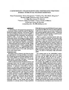
the design flow. The project uses the IBM Harmony1 process coupled with Rhapsody2 UML modeling tool. Additionally, MoPCoM proposes two distinct flows for system modeling and schedulability analysis that increase design efforts. Similarly, eDIANA [8] is an ARTEMIS project that uses MARTE profile for RTES specification and validation. However, detailed specification of software and hardware aspects are not illustrated in the project. While TOPCASED [9] differs from MADES, as it focuses primarily on IDE infrastructure for embedded systems and not on particular implementations. Project SATURN is [10] is another EU FP7 project that aims to use high level co-modeling approach for RTES simulation and synthesis goals. However, the project only takes SysML into account and proposes a number of UML profiles for co-simulation, synthesis and code generation purposes. The goal is to use carry out hardware/software modeling via these profiles and generate SystemC for eventual VHDL translation and FPGA implementation. Unfortunately, the project does not utilizes the MARTE profile for hardware/software co-design modeling. In [11], the authors provide a mixed modeling approach based on SysML and the MARTE profiles to address design space exploration strategies. However, the shortcomings of this approach is that they only provide implementation results by means of mathematical expressions and no actual experimental results were illustrated. The OMEGA European project [12] is also dedicated to the development of critical real-time systems. However it uses pure UML specifications for system modeling and proposes a UML profile [13], which is a subset of the earlier UML profile for Scheduling, Performance and Time (SPT), that has been integrated in MARTE. The MARTES project emphasizes on combined usage of UML and SystemC for systematic modelbased development of RTES. The results from this project in turn, have contributed to the creation of the MARTE profile. While INTERESTED [14] proposes a merged SysML/MARTE methodology where SysML is used for requirement specifications and MARTE for timing aspects, it does not proposes rules on combined usage of both profiles. The MADES project aims to resolve this issue and thus differentiates from the above mentioned related works, as it focuses on an effective language subset combining both SysML and MARTE profiles for rapid design and specification of RTES. The two profiles have been chosen as they are both widely used in embedded systems design, and are complimentary in nature [15]. MADES proposes automatic generation of hardware descriptions and embedded software from high level models, and integrates verification of functional and nonfunctional properties, as illustrated in the following section. III. MADES: GOALS AND METHODOLOGY In this section, we provide a brief overview of the MADES design methodology, as illustrated in Fig.1. Initially, the high level system design models are carried out using the MADES 1 http://www-01.ibm.com/software/rational/services/harmony/ 2 http://www-01.ibm.com/software/awdtools/rhapsody/
language and associated diagrams, which are represented later on in section IV. After specification of the design models that include user requirements, related hardware/software aspects and their eventual allocation along with schedulability analysis; underlying model transformations (model-to-model and model-to-text transformations) are used to bridge the gap between these abstract design models and subsequent design phases, such as verification, hardware descriptions of modeled targeted architecture and generation of platform specific embedded software from architecturally neutral software specifications. For implementing model transformations, MADES uses the Epsilon platform [16], that enables model transformations, code generation, model comparison, merging, refactoring and validation [17].
MADES language focuses on a subset of SysML and MARTE profiles and proposes a specific set of diagrams for specifying different aspects related to a system: such as requirements, hardware/software concepts, etc. Along with these specific unique diagrams, MADES also uses classic UML diagrams such as State and Activity diagrams to model internal behavior of system components, along with Sequence and Interaction Overview diagrams to model interactions and cooperation between different system elements. Softeam’s UML Modelio tool [23] enables full development of MADES diagrams and associated language, while a partial integration has been currently carried out for a MADES open source modeler, that is an extension of the Papyrus UML modeler [24]. We now provide a brief description of the MADES language and its related diagrams.
MADES Language Design Models
MHS descripƟon
VeriĮcaƟon scripts
User input
SimulaƟon scripts
Zot veriĮcaƟon
VHDL
Verification Hardware description generation
PlaƞormagnosƟc code
Hardware/ soŌware mappings
Hardware architecture descripƟon
Figure.2: Overview of MADES language design flow
Compile-Time VirtualizaƟon Plaƞorm-speciĮc code Embedded software generation
Figure.1: An overview of the global MADES methodology
In the initial specification phase, a designer needs to carry out system design at high abstraction levels. This design phase consists of the following steps: •
Verification activities in MADES comprise of verification of key properties of designed concepts (such as meeting deadlines, etc.) and that of model transformations integrated in the design flow [18], [19]. For verification and simulation purposes, MADES uses the Zot tool [20], that permits verification of aspects, such as meeting critical deadlines, among others. While closed-loop simulation on design models enable functional testing and early validation. Additionally, MADES employs the technique of CompileTime Virtualization (CTV) [21], for targeting of non-standard hardware architectures, without requiring development of new languages or compilers. Thus a programmer can write architecturally neutral code which is automatically distributed by CTV over a complex target architecture. Finally, code generation (either in C/C++ or VHDL) can be carried out that can be eventually implemented on modern state of the art FPGAs. Currently MADES targets Xilinx FPGAs, however it is also possible to adapt to FPGAs provided by other vendors such as Altera or Atmel. Detailed description regarding the global MADES methodology can be found in [22]. IV. MADES LANGUAGE : S YS ML/MARTE SUBSET Fig.2 gives an overview of the MADES language inherently present in the design flow for the initial design models. The
•
•
•
System Requirements: The user initially specifies the requirements related to the system. For this purpose, a MADES Requirements Diagram is utilized that integrates SysML requirements concepts. Use case Scenarios: Afterwards, the system requirements are converted into use cases, described using MADES Use Case Diagram that encapsulate SysML use case concepts. This design phase is strongly related to the functional high level specification described subsequently. High Level Specification: Each use case is converted into a SysML block by means of MADES High Level Block (or Internal Block) Specification Diagram, that contains SysML Block (or internal block) concepts respectively. This functionality is independent of any underlying execution platform and software details. It thus determines what is to be implemented, instead of how it is to be carried out. Refined High Level Specification: The Refined High Level Specification Diagram models MARTE components, each corresponding to a SysML block. Here, MARTE’s High level Application Modeling package is used to differentiate between active and passive components of the system.
The refined high level specification permits to link SysML and MARTE concepts while avoiding conflicts arising due
to parallel usage of both profiles [15]. The conflicts related to the two profiles are avoided as we do not mix SysML and MARTE concepts in the same diagram, but instead focus on a refinement scheme. Thus SysML is used for initial requirements and functional description, while MARTE is utilized for the enriched modeling of the global functionality and execution platform/software modeling. Thus, once the refined functional description is completed, the designer can move onto the partitioning of the system in question: depending upon the requirements and resources in hand, he or she can determine which part of the system needs to be implemented in hardware or software. We now describe the different steps related to each design level by means of MARTE concepts. Related to the MARTE modeling, an allocation between high level and refined high level specifications is carried out using a MADES Allocation Diagram. Afterwards, a codesign approach [25] is used to model the hardware and software aspects of the system. The modeling is combined with MARTE Non Functional Properties and Timed Modeling package to express aspects such as throughput, temporal constraints, etc. We now describe the hardware and software modeling, which are as follows: • Hardware Specification: The MADES Hardware Specification Diagram in combination with MARTE’s Generic Resource Modeling package enables modeling of abstract hardware concepts such as computing, communication and storage resources. The design level enables a designer to describe the physical system albeit at a abstraction level higher than the detailed hardware specification level. By making use of MARTE GRM concepts, a designer can describe a physical system such as a car, a transport system, flight management system, among others. • Detailed Hardware Specification: Using the Detailed Hardware Specification Diagram with MARTE’s Hardware Resource Modeling package allows extension and enrichment of concepts modeled at the hardware specification level. It also permits to model systems such as FPGA based System-on-Chips (SoCs), ASICs etc. A one-to-one correspondence usually follows here: for example, a computing resource typed as MARTE ComputingResource is converted into a hardware processor, such as a PowerPC or MicroBlaze [26], effectively stereotyped as MARTE HwProcessor. Once the detailed modeling is completed, an allocation diagram is then utilized to map the modeled hardware concepts to detailed hardware ones. • Software Specification: The MADES Software Specification Diagram along with MARTE’s Generic Resource Modeling package permits modeling of software aspects of an execution platform such as schedulers and tasks; as well as their attributes and policies (e.g. priorities, possibility of preemption). • Detailed Software Specification: The MADES Detailed Software Specification Diagram and related
MARTE’s Software Resource Modeling are used to express aspects of the underlying Operating System (OS). Once this model is completed, an allocation diagram is used to map the modeled software concepts to detailed software ones: for example, allocation of tasks onto OS processes and threads. This level can express standardized or designer based RTOS APIs. Thus multi-tasking libraries and multi-tasking framework APIs can be described here. Iteratively, several allocations can be carried out in our design methodology: a software to hardware allocation permits to associate schedulers and schedulable resources to related computing resources in the execution platform, once the initial abstract hardware/software models are completed. Subsequently this initial allocation could lead to further enriched allocation between the detailed software and hardware models (an allocation of OS to a hardware memory, for example). An allocation can also specify if the execution of a software resource onto a hardware module is carried out in a sequential or parallel manner. It should be noted that MARTE Generic Component Modeling package is used throughout the MADES diagrams dealing with MARTE stereotypes for describing the modeled concepts in a modular manner. Each MADES diagrams only contains commands related to that particular design phase, thus avoiding ambiguities of utilization of the various concepts present in both SysML and MARTE. Additionally, MARTE enables analysis based on schedulability and performance criteria. Once a complete system is specified and eventually allocated; UML behavioral diagrams can be used in association with MARTE Schedulability Analysis Modeling package for describing the behavior of system components or the system itself. The schedulability analysis helps to determine aspects such as worst case execution times, missed deadlines etc; which can be expressed by the high level models and in turn used as input for a schedulability analysis tool, providing results that enable Design Space Exploration aspects by modifying in turn the high level design models. Once the modeling aspects are completed, the high level models can be utilized by model transformations to produce intermediate or executable enriched models as well as code for eventual implementation. Afterwards, simulation can be carried out using third party tools to verify the correctness and functionality of the generated code before moving onto synthesis which enables to create actual implementation of a RTES, for example a prototype in case of an FPGA. For MADES, all these aspects related to verification, automatic code generation and hardware implementation have been detailed in [27]. We now present our case study that illustrates our combined SysML and MARTE design methodology. V. C AR C OLLISION AVOIDANCE S YSTEM C ASE S TUDY We now provide the car collision avoidance system (CCAS) case study that is modeled in Modelio using the MADES language and underlying methodology. Verification aspects, automatic code generation and hardware implementation re-
lated to the CCAS have been illustrated in [27], and are not the scope of this paper. The car collision avoidance system or CCAS for short, when installed in a vehicle, permits to detect and prevent collisions with incoming objects such as cars and pedestrians. The CCAS as shown in Fig.3 contains two types of detection modules. The first one is a radar detection module that emits continuous waves. A transmitted wave when collides with an incoming object, is reflected and received by the radar itself. The radar sends this data to an obstacle detection module, which in turn removes the noise from the incoming signal along with other tasks such as a correlation algorithm. The distance of the incoming object is then calculated and sent to a primary controller for appropriate actions.
Figure.3: The CCAS installed on a car to avoid collisions with incoming objects The image tracking module is the second detection module installed in the CCAS. It permits to determine the distance of the car from an object by means of image computation. The camera takes pictures of incoming objects and sends the data to a secondary controller, which executes a distance algorithm. If the results of the computation indicate that the object is closer to the car then a specified default value that means a collision can occur. The result of this data is then sent to the primary controller of the CCAS. The primary controller when receives the data, acts accordingly to the situation at hand. In case of an imminent collision, it can carry out some emergency actions, such as stopping the engine, applying emergency brakes; otherwise if the collision is not imminent, it can decrease the speed of the car and can apply normal brakes. We now describe the CCAS system in detail subsequently.
Here, the different requirements for the CCAS are described: the Global Collision Avoidance Strategy determines the global requirement for the system which is to detect incoming objects by means of either the radar or the image tracking system. Additional requirements can be derived from this global requirement, such as the Imminent Collision Strategy, Near Collision Avoidance Strategy, Additional Timing requirements and Changing Lanes Strategy. It should be noted that this requirement specification is not complete in nature and has a strong relation with other MADES diagrams. More specifically, these specifications rely on use case scenarios and the functional blocks, described in turn in High level Block Specification Diagram for their completion, as illustrated later on. We thus will revisit this requirement diagram once we specify these other aspects. Initially, the user describes the system requirements which state that if the distance from an object is less than 3 meters than the CCAS should enter in a warning state. If it remains in that state for 300 ms and distance is still less than 3 meters, then the CCAS should decrease car speed and alert the driver by means of an alarm and a Heads-up-display (HUD). If the distance falls to 2 meters, the CCAS should enter in a critical warning state. If it remains in that state for 300 ms and distance is still less than 2 meters, then CCAS should apply emergency brakes, deploy airbags and alert the driver as well. Gl o b a l Co lli s i o n A v o i d a n c e St r a t e g y Detect Colli sion by m eans of the installed r adar detection or by the im age tr ack ing sy stem . Switching betwee n r adar and im age tr ack ing depending upon user r equir em ents and weather conditions. Tak e app r opr iate actions to av oid colli sions and notify the dr iv er
I mm i n e n t Co lli s i o n St r a t e g y
A dd i t i o n a l T i m i n g r e q u i r e m e n t s
Ne a r Co lli s i o n A v o i d a n c e St r a t e g y
Ch a n g i n g La n e s St r a t e g y
When ex ter nal obj ect is less than 2 m eter s away , the dr iv er should be notified by an alar m and HUD, and sy stem should switch to a cr itical war ning state. I f the sy stem r em ains in cr itical war ning state f or m or e than 300 m s and distance f r om obj ect is still less than 2 m eter s then the engine should be stopp ed, br ak es should be app lied, seatbelts should be tensioned and air bag should be deploy ed. The br ak es should be app lied f or 100 m s
The r adar or the im age tr ack ing m odule should send the data to the Contr oller ev er y 100 m s v ia the sy stem bus and the comm un ication should tak e 20 m s, dur ing which the bus should be busy . I n case of imm inent colli sion, the contr oller should send the br ak e comm and which should tak e no m or e than 20 ms
When ex ter nal obj ect is less than 3 m eter s away , the contr oller should swi tch to a war ning state. I f the sy stem r em ains in this state f or 300 m s, then the dr iv er should b e notified v ia an alar m and HUD, nor m al b r ak es should be app lied for 10 m s f or r educing car spee d. Hazar d war ning lights should be activ ated in the HUD.
When the dr iv er is about to change lanes or if the car dev iates f r om the curr ent lane intentionally , the dr iv er should b e notified v ia the HUD. I f the dr iv er is chaning lanes him self, the car tur n signal should be on
Figure.4: Initial requirements specifications for the CCAS
Car Usecase Scenarios
Re v e r s e Ca r St a r t Ca r
A. SysML based modeling of CCAS The CCAS design specifications start with SysML based modeling, which involves the initial design decisions such as system requirements and functionality description. 1) Requirement Specifications: We first move on to the system requirements that basically describe the overall needs, constraints and limitations of the system. Using the SysML inspired MADES Requirements Diagram, it is possible to describe the system requirements at the initial phase of system conception. In Fig.4, we illustrate the different requirements of the CCAS system. It should be mentioned that only the functional requirements of a system are described at this level.
A v o i d Co lli s i o n s
D e c r e a s e Sp ee d Driver
D r i v e Ca r
A pp l y Br a k e s
St o p Ca r
No t i f i c a t i o n s t o o t h e r c a r s a n d p e d e s t r i a n s
Figure.5: The different case scenarios related to the CCAS 2) Use case scenarios: Once the requirement phase is partially completed, we move onto describing the use case scenarios associated with our system via the MADES Use Case Diagram. Here in Fig.5, we describe the different scenarios associated with the car on which the CCAS is installed. The
figure illustrates some basic scenarios, such as the car being started, stopped or being driven. The Avoid Collisions scenario makes use of other specified scenarios and is the one that is related to the system requirements described in the section.V-A1. 3) High Level Specification: Once the requirements and use case scenarios of our system are specified; we move onto the functional block description of the CCAS system as described in Fig.6. For this, MADES High Level Block Specification or High Level Internal Block Specification diagrams are used. This conception phase enables a designer to describe the system functionality without going into details how the functionality is to be eventually implemented. Here the functional specification is described using SysML block definition diagram concepts. The functional description can be specified by means of UML concepts such as aggregation, inheritance, composition etc. Equally, hierarchical composition of functional blocks can be specified by means of internal blocks, ports and connectors. Here we use these concepts for describing the global composition of the CCAS. The Car block is composed of some system blocks such as a Ignition System, Charging System, Starting System, Engine Component Parts, Transmission System and finally the Car Collision Avoidance Module which is the main component related to our case study. Each functional blocks can be composed of internal blocks, however, this step has not been illustrated in the paper. > Doo r s
> Window s 1 ..*
2 ..*
> W h ee l a n d T i r e Pa r t s 1
> A i r Co n d i t i o n e r Sy s t e m
1
> En g i n e Co m p o n e n t Pa r t s
1
> El e c t r i c Su pp l y Sy s t e m
1
0 ..1
0 ..1
> Ch a r g i n g Sy s t e m > Ga u g e s a n d Me t e r s > I g n i t i o n Sy s t e m
> Ca r
0 ..1 1 0 ..1 0 ..1
0 ..1
1 0 ..1 1
0 ..1 1
1
0 ..1
0 ..1
> A u d i o / Vi d e o Mu l t i m e d i a De v i c e s
0 0 ..1 ..10 ..1 0 ..1 0 ..1 0 ..1 0 ..1 0 ..1 0 ..1 1 0 ..1
1 1 1
> Sw i t c h e s
> W i r i n g Ha r n e ss e s > Su s p e n s i o n a n d St ee r i n g Sy s t e m > F u e l Su pp l y Sy s t e m > T r a n s m i ss i o n Sy s t e m > Ex h a u s t Sy s t e m
1
1
> St a r t i n g Sy s t e m
> Ca r Co lli s i o n A v o i d a n c e Mo d u l e
> En g i n e Oil Sy s t e m
1 1
1
> En g i n e Coo li n g Sy s t e m
Figure.6: High level specification using SysML block concepts
A v o i d Co lli s i o n s
Gl o b a l Co lli s i o n A v o i d a n c e St r a t e g y Detect Colli sion by m eans of the installed r adar detection or by the im age tr ack ing sy stem . Switching betwee n r adar and im age tr ack ing depending upon user r equir em ents and weather conditions. Tak e app r opr iate actions to av oid colli sions and notify the dr iv er
specification of our system, it is possible for us to complete the requirement specifications, as described in Fig.7. As seen here, a related use case scenario and a functional block has been added to the figure, which helps to complete and satisfy the high level system requirements. It should be noted here, that as seen in Fig.7, only the Car Collision Avoidance Module block specified in the diagram is utilized to satisfy the global system requirements. Thus, these system requirements can be refined once an initial functional specification of system is completed. Since we are only interested in the Car Collision Avoidance Module and not other functional blocks of the car, it is this module that is the focus of the subsequent design phases. B. MARTE based modeling of CCAS Once the initial design descriptions have been specified, it is possible to partition and enrich the high level functionalities. For this, MARTE concepts are used to determine which parts of the system are implemented in software or hardware along with their eventual allocation. Additionally, MARTE profile enables to express non-functional properties related to a system, such as throughput, worst case execution times, etc. We now describe the MARTE based design phases in the subsequent sections. 1) Refined High Level Specification: We now turn towards the MARTE based modeling of the CCAS. All necessary concepts present at the High Level Specification Diagram correspond to an equivalent concept at the Refined High Level Specification Diagram. Since we are only interested in the Car Collision Avoidance Module at the higher level specifications, an equivalent MARTE component is created. The RH Car Collision Avoidance Module is stereotyped as a MARTE RtUnit that determines the active nature of the component. Fig.8 shows the related modeling of this concept. The RtUnit modeling element is the basic building block that permits to handle concurrency in RTES applications [6]. It should be mentioned that component structure and hierarchy should be preserved between the two high level specification diagrams. As in this particular example, no hierarchical compositions are present at the high level specifications for Car Collision Avoidance Module, they are equally not present in the underlying refined high level specifications.
> RH_ Ca r Co lli s i o n A v o i d a n c e Mo d u l e
Figure.8: Refined high level specification of the CCAS
I mm i n e n t Co lli s i o n St r a t e g y
A dd i t i o n a l T i m i n g r e q u i r e m e n t s
Ne a r Co lli s i o n A v o i d a n c e St r a t e g y
Ch a n g i n g La n e s St r a t e g y
When ex ter nal obj ect is less than 2 m eter s away , the dr iv er should be notified by an alar m and HUD, and sy stem should switch to a cr itical war ning state. I f the sy stem r em ains in cr itical war ning state f or m or e than 300 m s and distance f r om obj ect is still less than 2 m eter s then the engine should be stopp ed, br ak es should be app lied, seatbelts should be tensioned and air bag should be deploy ed. The br ak es should be app lied f or 100 m s
The r adar or the im age tr ack ing m odule should send the data to the Contr oller ev er y 100 m s v ia the sy stem bus and the comm un ication should tak e 20 m s, dur ing which the bus should be busy . I n case of imm inent colli sion, the contr oller should send the br ak e comm and which should tak e no m or e than 20 ms
When ex ter nal obj ect is less than 3 m eter s away , the contr oller should swi tch to a war ning state. I f the sy stem r em ains in this state f or 300 m s, then the dr iv er should b e notified v ia an alar m and HUD, nor m al b r ak es should be app lied for 10 m s f or r educing car spee d. Hazar d war ning lights should be activ ated in the HUD.
When the dr iv er is about to change lanes or if the car dev iates f r om the curr ent lane intentionally , the dr iv er should b e notified v ia the HUD. I f the dr iv er is chaning lanes him self, the car tur n signal should be on
> Ca r Co lli s i o n A v o i d a n c e Mo d u l e
> Ca r Co lli s i o n A v o i d a n c e Mo d u l e {kind (hybrid), nature (spatialAllocation)}
> RH_ Ca r Co lli s i o n A v o i d a n c e Mo d u l e
Figure.7: Completing the functional specifications of the CCAS
Figure.9: Allocation between high level/refined high level specifications
4) Completing the Requirement Specifications: Once we have finished the use case scenarios and functional block
2) Allocating High Level and Refined High Level Specifications: Afterwards, an allocation using the MADES Allocation
Diagram is used to map the high level specification concepts to the refined high level specification concepts. This aspect is represented in Fig.9. Using the MARTE allocation mechanism, we express that the allocation is hybrid (both structural and behavioral aspects are thus related from source to target) and spatial in nature. 3) Clock Specification: Once the initial specification has been carried out, modeling of hardware and software aspects of the required functionality is possible in a parallel manner. For that purpose, we first model the different clock types which are used by the execution platform of the CCAS, as illustrated in Fig.10. Here, an initial ideal clock type serves as the basis for the Hardware and System clock types. All the clocks types are discrete in nature using the MARTE Time package.
hardware components. Here, the hardware specification also contains a clock sysclk of the type SystemClock specified earlier in Fig.10. Here using the MARTE Time package, we add a clock constraint onto the clock, specifying that this clock (and related clock type) runs at a rate 10 times faster than that of the ideal clock. The hardware specification contains different hardware components which themselves are either further composed of sub components, or have internal behaviors, expressed by means of classic UML behavioral diagrams. We now describe the internal behavior of three hardware components: SystemC lock
receivingData
C C AS Time Domain > I d e a l Cl o c k { n a t u r e ( d i s c r e t e ) , i s Lo g i c a l }
> Ha r d w a r e Cl o c k { n a t u r e ( d i s c r e t e ) , r e s o l A tt r ( 10 ) }
Figure.12: Behavior of the radar module present in the CCAS
> Sy s t e m Cl o c k { n a t u r e ( d i s c r e t e ) , r e s o l A tt r ( 10 ) }
Figure.10: Specification of clock types related to CCAS
notifyDistanceEnd [distance < 3 meters] notifyDistanceEnd [distance > 3 meters]
We first define time domain to contain the clock types related to the system. For this, a package CCAS Time Domain stereotyped as TimedDomain is created, respecting the timing notions in MARTE. Afterwards, we specify the clock types present in our system as illustrated in the figure. We specify three clock types: IdealClock, SystemClock and HardwareClock; all appropriately stereotyped as ClockType. The IdealClock is the basic clock type present in the system referencing a certain frequency, while the other two reference this basic clock and run at much higher frequencies.
notifyDistanceEnd [distance < 3 meters && @warning.exit - @warning.enter < 300 ms]^breakInterrput noAction notifyDistanceEnd [distance < 2 meters && @criticalwarning.exit - @criticalwarning.enter < 300 ms]^breakInterrput notifyDistanceEnd [distance >= 3 meters]
criticalwarning
notifyDistanceEnd [distance > 2 meters]
notifyDistanceEnd [distance < 2 meters]
Figure.13: Behavior of the primary controller of the CCAS
notifyNormalBrakeEnd
idle
normalBraking
[@normalBraking.exit - @normalBraking.enter = 10 ms] notifyEmergencyBrakeEnd
C ons traint {T he Sys temC loc k has a rate 10 times fas ter than the I dealC loc k}
sys clk :Syste m C lock
warning
emergencyBraking
[@emergencyBraking.exit - @emergencyBraking.enter = 100 ms] ctrl:C ontrolle r
sha re d m e m :Sha re d Me m ory
ctrl m e m :C ontrolle r Me m ory im g proc:Im a ge P roce ss or Se conda r C ontrolle r
Figure.14: Internal behavior of the braking system
odm :O bsta cle De te ction Module ra da r:R a da r a la rm :Ala rm a dd se ns:Add itiona l Se nsors ligh-sig sys:Lightning a nd Signa ling Syste m bra k ing sys:Bra k ing Syste m
im g m e m :Im a ge P roce ss or Me m ory ca n:C AN
ca m :C a m e ra displa y:HUD Displa y be lts:Se a t be lts a ir ba g:Air ba g
Figure.11: Abstract hardware specification of CCAS 4) Hardware Specification: At the hardware specification level, we first model the abstract hardware concepts of the execution platform in Fig.11. The abstract hardware modeling of the execution platform of the CCAS contains primary and secondary controllers for radar/image tracking modules, their respective local and shared memories, system clock and additional hardware resources (radar and camera modules, braking system, etc.); all of which communicate via a CAN bus. The MARTE GRM package stereotypes are applied onto the different hardware resources: for example ComputingResource for the primary and secondary controllers, StorageResource for the local and shared memories, CommunicationMedia for the CAN bus, while DeviceResource is used for the other
In Fig.12, we describe the internal behavior of the Radar component by means of a state machine diagram. The RadarBehavior state machine is stereotyped as TimedProcessing (not shown in the Figure). This permits to bind the processing of this behavior to time by means of a clock. Here the Radar remains in a single receivingData state and continues to send data to the primary controller at each tick of the SystemClock, every 100 ms. While Fig.13 illustrates the internal behavior of the primary controller. The controller contains three states, noAction, warning and criticalwarning. The controller initially remains in the noAction state when distance from incoming objects is greater than 3 meters. If the distance decreases to less than 3 meters, the controller switches to either warning or criticalwarning state (depending upon the the related condition) and sends a braking command to the Braking System. Fig.14 illustrates behavior of the Braking System. It switches to either the normalBraking or the emergencyBraking state, depending upon receiving a particular command from the primary controller.
oD M C ontroll erC ommunic atio n radarO D M C ommunic atio n
Ra d a r ODMCo mm un i c a t i o n 1
send sensor distance(in distance : integer)
radarO D M C ommunic atio n 1
> ODM T a s k
> Ra d a r T a s k
1
send switch comm and()
s ys tem Sc heduler
> Br a k e A c t u a t o r T a s k
brake A c tuator T as k
Notify Brake() Em ergency Brakes()
1
Sensor O peration() SwitchtoIm age()
> I m g Co n t r o ll e r T a s k
Norm al Brakes()
> A i r Ba g T a s k
air Bag T as k c ontroll erBrakeC ommunic atio n
Notify Im age() SwitchtoRadar()
1
Notify Air Bag Comm and()
Co n t r o ll e r Br a k e Co mm un i c a t i o n
> Se a t Be l t s T a s k
s eat Belts T as k
Co n t r o ll e r A i r b a g Co mm un i c a t i o n
c ontroll erA irbagC ommunic atio n
1 imgC ontroll erC amC ommunic atio n
c ontroll erSeatbeltC ommunic atio n
Co n t r o ll e r Li g h t Sy s Co mm un i c a t i o n
1
Notify Light Sys Comm and() Indicator Signal()
send lightning system comm and()
Co n t r o ll e r Se n s o r Co mm un i c a t i o n
c ontroll erSens orC ommunic atio n 1
> Ala r m Ta sk Notify Alarm Comm and() Soun d Alarm ()
1
> Li g h t Sy s t e m s T a s k
li ght Sys tems T as k
1
Take Picture()
send sensor swee p comm and()
c ontroll erA larmC ommunic atio n alarm T as k
1
Co n t r o ll e r A l a r m Co mm un i c a t i o n
> Se n s o r T a s k
s ens or T as k 1
Notify Sensor Task() Perform W eather tem perature sensor swee p()
send alarm notification comm and()
1
comm 8:C ontrolle rAirbagC omm un ication
cam T:C am e ra Task
comm 3:C ontrolle rDispC omm un ication comm 9:C ontrolle rBrak e C omm un ication comm 4:C ontrolle rSe atbe ltC omm un ication
im gctrlT:Im g C ontrolle r Task
comm 10 :C trlToIm gC trlC omm un ication
comm 5:C ontrolle rLightSysC omm un ication
comm 11 :Im gC ontrolle rC am C omm un ication
share d m e m :Share d Me m ory
{nature (timeScheduling)} im g proc:Im age Proce ss or Se condar C ontrolle r
im g m e m :Im age Proce ss or Me m ory
brak ing sys:Brak ing Syste m
can:C AN
{nature (spatialAllocation)} odm T:O DM Task
odm :O bstacle De te ction Module radar:R adar
radarT:R adar Task {nature (spatialAllocation)} sche dule r:Syste m Sche dule r
{nature (timeScheduling)} ctrl:C ontrolle r
ctrlT:C ontrolle r Task {nature (timeScheduling)}
cam :C am e ra
alarm T:Alarm Task {nature (timeScheduling)}
Re fresh Display()
send display refresh comm and()
c ontroll erL ightSys C ommunic atio n c amera T as k
> Di s p l a y Re f r e s h T a s k dis play Refres h T Notify as k Display Comm and() 1
1
> Ca m e r a T a s k
Tighten Seat Belts()
Co n t r o ll e r Se a t b e l t Co mm un i c a t i o n
Co n t r o ll e r Di s p Co mm un i c a t i o n
c ontroll erD is pC ommunic atio n
comm 6:C ontrolle rSe nsorC omm un ication comm 7:C ontrolle rAlarm C omm un ication
comm 2:O DMC ontrolle rC omm un ication
Notify Seat Belts Comm and()
send seat belt comm and()
1
I m g Co n t r o ll e r Ca m Co mm un i c a t i o n send im age comm and()
1
send air bag comm and()
1
comm 1:R adarO DMC omm un ication
{nature (timeScheduling)}
Deploy Air Bag()
send brake comm and()
1
Perform Scheduling()
0 ..1
Brake O peration()
Alarm O peration() Display Upd ate()
1 c trlT oI mgC trlC ommunic atio n
> Sy s t e m Sc h e d u l e r
> Co n t r o ll e r T a s k
Notify Distance(in distance : integer) Air Bag O peration() Seat Belt O peration() Lighting Control O peration()
c trlT oI mgC trlC ommunic atio n
Ct r l T o I m g Ct r l Co mm un i c a t i o n
> Sc h e d u l e r T i m e r
1 oD M C ontroll erC ommunic atio n
Notify Raw Data(in raw data : integer) Perform Calculation()
getData(in data : integer)
ODMCo n t r o ll e r Co mm un i c a t i o n 1
send raw data(in data : integer)
{nature (timeScheduling)}
be lts:Se at be lts
{nature (timeScheduling)}
display:HUD Display
{nature (timeScheduling)} air bag:Air bag
alarm :Alarm
{nature (timeScheduling)}
add se ns:Add itional Se nsors
{nature (timeScheduling)}
ligh-sig sys:Lightning and Signaling Syste m
{nature (timeScheduling)} ctrl m e m :C ontrolle r Me m ory
dispT:Display Re fre sh Task brak e T:Brak e Actuator Task se nsorT:Se nsor Task sbe ltT:Se at Be lts Task lightT:Light Syste m s Task abagT:Air Bag Task
Figure.15: Software specification of the CCAS Figure.17: Mapping software resources to the hardware modules of CCAS
schTim e r:Sche dule r Tim e r
sche dule r:Syste m Sche dule r
comm1 1
odm T:O DM Task
comm 1:R adarO DMC omm un ication radarT:R adar Task
comm2 ctrlT:C ontrolle r Task
1 1
sensorT
comm1
1
comm 2:O DMC ontrolle rC omm un ication
1 ctrlT
comm6
comm10
1
dispT 1 abagT
1 comm 10 :C trlToIm gC trlC omm un ication
imgctrlT
1 im gctrlT:Im g C ontrolle r Task comm11
1 camT comm 11 :Im gC ontrolle rC am C omm un ication 1 cam T:C am e ra Task
comm 6:C ontrolle rSe nsorC omm un ication
comm3
comm 3:C ontrolle rDispC omm un ication
1 comm8
comm 8:C ontrolle rAirbagC omm un ication
1 comm4
comm 4:C ontrolle rSe atbe ltC omm un ication
1 comm9
comm 9:C ontrolle rBrak e C omm un ication
1 comm5 1 comm7 1
1 sbeltT 1 brakeT 1 lightT 1
se nsorT:Se nsor Task dispT:Display Re fre sh Task abagT:Air Bag Task sbe ltT:Se at Be lts Task brak e T:Brak e Actuator Task lightT:Light Syste m s Task
comm 5:C ontrolle rLightSysC omm un ication comm 7:C ontrolle rAlarm C omm un ication
alarmT 1
alarm T:Alarm Task
Figure.16: Software specification of the CCAS (Instance level)
5) Software Specification: We now turn towards modeling of the software specification of the execution platform of the CCAS, as displayed in Fig.15. Here, schedulable tasks related to the hardware modules are modeled along with their communications. A scheduler is also present that manages the overall scheduling based on a fixed priority algorithm. The different tasks are stereotyped as SchedulableResource, indicating that they are scheduled by means of a System Scheduler, itself appropriately stereotyped as a Scheduler. Each task contains a number of operations, indicating the functionality related to that particular task. The software specification is also modeled at the instance level as illustrated in Fig.16, for an eventual allocation between the software/hardware specifications, and also for schedulability analysis modeling using UML sequence diagrams, as illustrated later on in section V-B12. 6) Allocating Software to Hardware: Once the hardware and software specifications have been carried out, we carry out an allocation between the two using the MADES Allocation Diagram. Here in Fig.17, the majority of the tasks (such as Brake Actuator Task, Air Bag Task) are allocated to the primary controller by means of a temporal allocation. Similarly, the Radar and ODM tasks are allocated to their respective hardware modules by means of spatial allocations. While tasks related to the secondary controller such as Camera Task are mapped on to it by means of a temporal allocation. Finally, all the communications are allocated to the CAN bus. It should be noted that while the Allocated stereotype on the software and hardware concepts has been applied similarly to the concepts illustrated in Fig.9, they have not been displayed here for a better visualization.
7) Detailed Hardware Specification: Once the initial abstract hardware specification has been modeled, the designer can move on to modeling of the detailed hardware specification which corresponds more closely to the actual implementation details of the execution platform. The structure of the detailed hardware specifications corresponds to the abstract specifications specified in Fig.11, but have been enriched with additional details: such as operating frequencies of the primary and secondary controllers, for example. All these aspects have been represented in Fig.18. Here, the modeled computing resources are stereotyped as HwProcessor, while memories are typed as HwRAM. The sensors, radar and display modules as typed as HwI O, while remaining hardware concepts are stereotyped as HwDevice. Additionally the communication module, the HW ChannelBox has been typed as a HwMedia. Finally, the execution platform also contains a hwclk clock of type HardwareClock with a related clock constraint. C ons traint {T he H ardwareC loc k has the s ame rate as the Sys temC loc k}
hwclk :Hardware Clock
ppc:PowerPC {op_Frequencies (300MHz)} hwctrlm e m :HW _ControlMe m
hwshare dm e m :HW _Share dMe m
hwim gctrl:HW _Im gControlle r
hwodm :HW _O DM hwradar:HW _R adar hwalarm :HW _Alarm hwse ns:HW _Se nsors
hwchann e lbox :HW _Chann e lBox
hwim gm e m :HW _Im gMe m hwcam :HW _Cam e ra hwdisplay:HW _Display
hwlss :HW _LightSys
hwbe lts:HW _Se atBe lts
hwbss :HW _Brak e Sys
hwairbag:HW _AirBag
Figure.18: Detailed hardware specification of the execution platform 8) Detailed Software Specification: In parallel, a designer can model the detailed software specification, which basically correspond to expressing the concepts related to the underlying operating system of the CCAS. While it is possible to carry out detailed modeling of the operating system using MARTE SRM concepts, by adding relevant details such as semaphores, deadlocks, memory brokers etc; we chose to only illustrate some basic concepts related to a generic operating system.
Here as seen in Fig.19, the operating system has processes, each of which contains a number of threads. The Operating System is stereotyped according to SRM concepts as a SwResource, while the Process concept is typed as a SwSchedulableResource and a MemoryPartition. The latter stereotype indicates an address space which will be shared by the different threads associated with a process. Also, the Thread is itself typed as SwSchedulableResource. > Op e r a t i n g Sy s t e m 0 ..1 proc es s
*
> Pr o c e s s
thread 1 ..*
0 ..1
> Th r e a d
Figure.19: Detailed software specification of the execution platform 9) Allocating Hardware to Detailed Hardware Specifications: Once the detailed hardware specification has been modeled, we can carry out an allocation linking hardware to the detailed hardware specifications. This allocation corresponds to a one to one mapping between the two specifications, and thus determines the refinement of the execution platform. Thus, it enables to move from abstract classifications to details corresponding closely to RTL implementation. For example a Controller (and its related instance) is mapped to a PowerPC processor (and its instance), as shown in Fig.20. It should be mentioned that the Allocated stereotype applied on the allocated source/target concepts is not illustrated in the figure. sys clk :Syste m C lock ctrl:C ontrolle r
hwclk :Hardware C lock
brak ing sys:Brak ing Syste m
ppc:PowerPC
air bag:Air bag
ctrl m e m :C ontrolle r Me m ory
hwctrlm e m :HW _C ontrolMe m
im g proc:Im age Proce ss or Se condar C ontrolle r
hwim gctrl:HW _Im gC ontrolle r
im g m e m :Im age Proce ss or Me m ory
hwim gm e m :HW _Im gMe m
share d m e m :Share d Me m ory
hwshare dm e m :HW _Share dMe m
can:C AN
hwchann e lbox :HW _C hann e lBox
odm :O bstacle De te ction Module
hwbss :HW _Brak e Sys hwairbag:HW _AirBag
hwcam :HW _C am e ra
radar:R adar
hwradar:HW _R adar
alarm :Alarm
be lts:Se at be lts
hwbe lts:HW _Se atBe lts
ligh-sig sys:Lightning and Signaling Syste m
hwlss :HW _LightSys
display:HUD Display
hwdisplay:HW _Display
hwse ns:HW _Se nsors
cam :C am e ra
hwodm :HW _O DM
add se ns:Add itional Se nsors
hwalarm :HW _Alarm
the detailed software specification (the operating system in this case), in Fig.21. All the tasks and communications are allocated onto the operating system. While it is also possible to model the detailed software modeling in a detailed manner (different threads corresponding to the different tasks at software specifications) and then carry a one to one allocation, this aspect has not been carried out in the paper. 11) Allocating Detailed Software to Detailed Hardware Specifications: Finally, once all the detailed specifications related to the software and hardware aspects of the execution platform have been modeled, it is possible to carry out a final allocation from the detailed software to the detailed hardware specifications. Here, as seen in Fig.22, the operating system is allocated onto the local memory of the primary controller, by means of a spatial allocation. > Op e r a t i n g Sy s t e m {nature (spatialAllocation), kind (hybrid)} hwctrlm e m :HW _C ontrolMe m
Figure.22: Allocating the detailed software and hardware specifications 12) Schedulability Analysis Specifications: Once the software and hardware modeling have been carried out, using the MADES language, it is possible to carry out schedulability analysis at the high level models. Here, in the following figures, we illustrate schedulability analysis aspects related to some modules of the execution platform. However, it is equally possible to analysis the whole system in question. radarT:R adar Task
comm 1:R adarO DMC omm un ication
odm T:O DM Task
comm 2:O DMC ontrolle rC omm un ication
ctrlT:C ontrolle r Task
se nd raw data( d ) {e x e cTim e (10 m s,m ax ) , (8m s,m in )} Notify R aw Data( d ) {e x e cTim e (10 m s,m ax ) , (8m s,m in )}
Pe rform C alculation( ) {e x e cTim e (3m s,m ax ) , (2m s,m in )}
Figure.20: Allocating hardware/detailed hardware specifications
se nd se nsor distance ( d ) {e x e cTim e (10 m s,m ax ) , (8m s,m in )}
Notify Distance ( d ) {e x e cTim e (10 m s,m ax ) , (8m s,m in )}
> A i r Ba g T a s k
> Ra d a r T a s k > Sy s t e m Sc h e d u l e r
ODMCo n t r o ll e r Co mm un i c a t i o n
Co n t r o ll e r Se n s o r Co mm un i c a t i o n
> Se a t Be l t s T a s k > Li g h t Sy s t e m s T a s k
> Op e r a t i n g Sy s t e m
Co n t r o ll e r Br a k e Co mm un i c a t i o n
Ct r l T o I m g Ct r l Co mm un i c a t i o n
> I m g Co n t r o ll e r T a s k
> Di s p l a y Re f r e s h T a s k
Co n t r o ll e r Di s p Co mm un i c a t i o n Co n t r o ll e r A l a r m Co mm un i c a t i o n
> Ala r m Ta sk > Br a k e A c t u a t o r T a s k > Ca m e r a T a s k
I m g Co n t r o ll e r Ca m Co mm un i c a t i o n Co n t r o ll e r Se a t b e l t Co mm un i c a t i o n
Figure.23: Sequence SendSensorDistanceToContrl for radar/controller communication
> ODM T a s k
Ra d a r ODMCo mm un i c a t i o n Co n t r o ll e r Li g h t Sy s Co mm un i c a t i o n
> Se n s o r T a s k
> Co n t r o ll e r T a s k
Co n t r o ll e r A i r b a g Co mm un i c a t i o n
Figure.21: Allocating software/detailed software specifications 10) Allocation Software to Detailed Software Specifications: Similarly, the software specification is allocated onto
In Fig.23, the UML sequence diagram illustrates the communication flows between the different tasks of the execution platform. The radarT instance of the Radar Task sends data to the odmT instance of the ODM Task by means of a communication: comm1 instance of RadarODMCommunication. The instance of the ODM Task after carrying out a noise reduction algorithm, sends the distance to the instance ctrlT of the Controller Task by means of the comm2 communication instance of ODMControllerCommunication. Using appropriate MARTE packages, it is possible to carry out schedulability analysis: such as determination of average and worst case execution times for these flows. For example, the SaStep
stereotype helps to express worst and best case execution times, while SaCommStep can additionally express the size of the message transmitted or received during the communication flow. Here, the sequence SendSensorDistanceToContrl is itself stereotyped as a GaScenario (not shown in the figure), indicating it is one of the possible scenarios related to the system.
breakInterrput
C lockEvent
>
>
SendSensorDistanceToC ontrl
SendBrakeC ommand
{ResourceUsage_ModelElement_execTime(43ms )}
{ResourceUsage_ModelElement_execTime(26ms )}
Figure.24: The CCAS InteractionOverview interaction Finally, an interaction overview diagram as shown in Fig.24, illustrates the overall behavior related to two possible scenarios. The second scenario SendBrakeCommand has not illustrated due to space limitations. While it is possible to include other possible scenarios related to the CCAS (such as switching to camera based mode, applying normal brakes) and carry out a schedulability analysis of the whole CCAS execution platform, here only a partial analysis has been shown for clarification purposes. Here the figure indicates that once the CCAS system starts, it enters into a loop. It remains in the first scenario while keeps getting clock ticks at regular time intervals, as displayed by the ClockEvent typed as GaWorkloadEvent. It keeps executing the first sequence until a brakeInterrupt event occurs, causing the system to execute the sequence related to the second scenario concurrently. As the system does not stop its execution, no final node has been represented in the figure. Finally the interaction CCAS InteractionOverview is stereotyped as a GaWorkloadBehavior (not shown in the figure). This stereotype is used to specify a set of related system-level operations, each associated with its respective behavior and executed on the basis of associated (workload) events. VI. C ONCLUSIONS This article aims to present a complete methodology integrated in the EU MADES project, for the design and development of real-time and embedded systems using an effective subset of UML profiles: SysML and MARTE. The paper presents its contributions by proposing an effective subset of the two profiles, forming the basis of MADES language and proposes unique set of diagrams to increase design productivity, decrease production cycles and promote synergy between the different designers/teams working at different domain aspects of the global system in consideration. Our MADES methodology could inspire future revisions of the SysML and MARTE profiles and may eventually aid in their evolution. Finally, the different language concepts and associated diagrams in the methodology have been illustrated in a case study related to a car collision avoidance system.
VII. ACKNOWLEDGEMENTS This research presented in this paper is funded by the European Community’s Seventh Framework Program (FP7/20072013) under grant agreement no. 248864 (MADES). R EFERENCES [1] OMG, “Portal of the Model Driven Engineering Community,” 2007, http://www.planetmde.org. [2] S. Sendall and W. Kozaczynski, “Model Transformation: The Heart and Soul of Model-Driven Software Development,” IEEE Software, vol. 20, no. 5, pp. 42–45, 2003. [3] A. Bagnato et al, “MADES: Embedded systems engineering approach in the avionics domain,” in First Workshop on Hands-on Platforms and tools for model-based engineering of Embedded Systems (HoPES), 2010. [4] MADES, “EU FP7 Project,” 2011, http://www.mades-project.org/. [5] Object Management Group Inc, “Final Adopted OMG SysML Specification,” mai 2006, http://www.omg.org/cgi-bin/doc?ptc/06-0504. [6] OMG, “Modeling and Analysis of Real-time and Embedded systems (MARTE),” 2010, http://www.omg.org/spec/MARTE/1.0/PDF. [7] A. Koudri et al, “Using MARTE in the MOPCOM SoC/SoPC CoMethodology,” in MARTE Workshop at DATE’08, 2008. [8] EDIANA, “ARTEMIS project,” 2011, http://www.artemis-ediana.eu/. [9] TOPCASED, “The Open Source Toolkit for Critical Systems,” 2010, http://www.topcased.org/. [10] W. Mueller et al., “The SATURN Approach to SysML-based HW/SW Codesign,” in IEEE Computer Society Annual Symposium on VLSI (ISVLSI), 2010. [11] M. Mura et al, “Model-based Design Space Exploration for RTES with SysML and MARTE,” in Forum on Specification, Verification and Design Languages (FDL 2008), 2008, pp. 203–208. [12] Information Society Technologies, “OMEGA: Correct Development of Real-Time Embedded Systems ,” 2009, http://www-omega.imag.fr/. [13] L. Ober et al., “Projet Omega : Un profil UML et un outil pour la modelisation et la validation de systemes temps reel,” 2005, pp. 73: 33–38. [14] INTERESTED, “EU FP7 Project,” 2011, http://www.interestedip.eu/index.html. [15] H. Espinoza et al, “Challenges in Combining SysML and MARTE for Model-Based Design of Embedded Systems,” in ECMDA-FA’09. Springer-Verlag, 2009, pp. 98–113. [16] D.S. Kolovos et al, “Eclipse development tools for Epsilon,” in Eclipse Summit Europe, Eclipse Modeling Symposium, 2006. [17] N. Matragkas et al., “D4.1: Model Transformation and Code Generation Tools Specification,” Tech. Rep., 2010, http://www.mades-project.org/. [18] L. Baresi et al., “D3.1: Domain-specific and User-centred Verification,” Tech. Rep., 2010, http://www.mades-project.org/. [19] ——, “D3.3: Formal Dynamic Semantics of the Modelling Notation,” Tech. Rep., 2010, http://www.mades-project.org/. [20] M. Pradella et al, “The Symmetry of the Past and of the Future: Biinfinite Time in the Verification of Temporal Properties,” in ESECFSE’07. New York, NY, USA: ACM, 2007, pp. 312–320. [21] I. Gray and N. Audsley, “Exposing non-standard architectures to embedded software using compile-time virtualisation,” in International conference on Compilers, architecture, and synthesis for embedded systems (CASES’09), 2009. [22] Ian Gray et al., “Model-based hardware generation and programming - the MADES approach,” in 14th International Symposium on Object and Component-Oriented Real-Time Distributed Computing Workshops, 2011. [23] Modelio, “UML Modeling tool,” 2011, www.modeliosoft.com. [24] Papyrus, “Open source tool for UML modeling,” 2011, http://www.papyrusuml.org/. [25] D.D. Gajski and R. Khun, “New vlsi tools,” IEEE Computer, vol. 16, pp. 11–14, 1983. [26] Xilinx, “MicroBlaze Soft Processor Core ,” 2011, http://www.xilinx.com/tools/microblaze.htm. [27] A. Bagnato et al, “D1.3: MADES Initial Approach Guide,” Tech. Rep., 2010, http://www.mades-project.org/.