... Dettwiler and Associates Ltd., 3800 Commerce Parkway, Richmond, BC, V6V 2J3, Canada ..... An Aurora is on the ground at Comox but needs 20 minutes.
A System for Testing Distributed Information Fusion Applications for Maritime Surveillance a
Hans Wehna, Jens Happea, Adel Guitounib, Pierre Valinb, Éloi Bosséb MacDonald, Dettwiler and Associates Ltd., 3800 Commerce Parkway, Richmond, BC, V6V 2J3, Canada b Defence R&D Canada (DRDC) Valcartier, 2459 Blvd. Pie XI Nord, Québec, QC, G3J 1X5, Canada ABSTRACT
A PRECARN partnership project, called CanCoastWatch (CCW), is bringing together a team of researchers from industry, government, and academia for creating an advanced simulation test bed for the purpose of evaluating the effectiveness of Network Enabled Operations in a Coastal Wide Area Surveillance situation. The test bed allows experimenting with higher-level distributed information fusion, dynamic resource management and configuration management given multiple constraints on the resources and their communications networks. The test bed provides general services that are useful for testing many fusion applications. This includes a multi-layer plug-and-play architecture, and a general multi-agent framework based on John Boyd's OODA loop.
Keywords: surveillance, information fusion, distributed fusion, software agents, simulation, test bed 1. INTRODUCTION The large volume surveillance problem faced by Canada is characterized by the employment of mobile (maritime patrol aircraft, helicopters, UAVs, ships) and fixed surveillance assets (e.g. land radar) to a large geographic area in order to identify, assess and track the maximum number of moving, stopped or drifting objects. The observed objects are not necessarily aware of being observed and are cooperative or non-cooperative, and friendly or hostile. Coastal and Arctic Wide Area surveillance are good examples of large volume surveillance. The scarce surveillance (e.g. Electro-Optical (EO), Infra-Red (IR), and Synthetic Aperture Radar (SAR) sensors) and tracking capabilities (normal radar modes) make it very difficult to perform large volume surveillance and to keep track of all activities. The best strategy for information communication, fusion, resource management and scheduling in such dynamically changing environments is poorly understood. Traditional methods in AI and Mathematical Programming assume a static and non-distributed problem. Unfortunately, often neither assumption is valid. The resource-scheduling problem is dynamically changing as the environment and requirements change due to continuing information updates. Moreover, not all information is always available to all parts of the network. There are communication and computing delays, bandwidth constraints, and communication losses to consider. With multiple surveillance platforms there is a need to network them, and keep each current on the evolving situation. Initial resource deployment starts a dynamically improving awareness picture of the current situation. Ancillary information will continually be supplied from external sources and contribute to the evolution of the situation assessment. The measurements taken by any one platform need to be distilled into information that improves the situation awareness. This is the role of data fusion in the CanCoastWatch (CCW) project, which is reported here. While traditional Level-1 fusion fuses sensor contacts into tracks, CCW starts at the track level and focuses on higher-level information fusion. It attempts to assert high-level propositions about the targets: their intentions, their relationships to each other and their relationships to the environment. To do this, it needs to employ higher-level reasoning. The defense research group at DRDC Valcartier is working on finding solutions to this large volume surveillance problem in support of the Canadian Forces. They identified a need for a test bed that can help with the evaluation of the effectiveness of the proposed solutions. The test bed should allow experimenting with higher-level distributed information fusion, dynamic resource management and configuration management given multiple constraints on the resources and their communications networks. This task was taken on by collaboration between industry, government, and academia, and partially funded by Precarn. Some aspects of CCW have been reported already in [1-2].
Multisensor, Multisource Information Fusion: Architectures, Algorithms, and Applications 2008, edited by Belur V. Dasarathy, Proc. of SPIE Vol. 6974, 69740E, (2008) · 0277-786X/08/$18 · doi: 10.1117/12.777811 Proc. of SPIE Vol. 6974 69740E-1 2008 SPIE Digital Library -- Subscriber Archive Copy
This paper provides a description of the test bed architecture (section 2), the important concepts of goals and situation evidence (section 3), distributed information fusion (section 4), dynamic resource management (section 5), vignettes (section 6), and conclusions (section 7).
2. MULTI-AGENT ARCHITECTURE The test bed provides a general multi-agent architecture based on John Boyd's OODA loop (i.e. Observe, Orient, Decide, Act) [3-4]. Due to the general nature of the OODA agents, very diverse elements can be modeled by it. They include ships, airplanes and fixed radar stations, but also collections of assets such as squadrons, or individual sensors if required. This great flexibility is further enhanced by a multi-layer plug-and play architecture that lets researchers easily add their own algorithms to CCW. The test bed provides general services that are useful for testing surveillance applications. The high-level architecture is depicted in Figure 1. The user-defined OODA agents, called nodes in CCW, are at the center of the system. They are supported by an editor, a test bed proper, and a viewer. The editor makes it easy to configure the simulation. For example, it allows for the specification of the node behaviour, and the setting up of the scenario and the environmental conditions. The editor also allows specification of the relationships between nodes, such as one node being the superior of another node. The output of the editor is an XML file that contains all the information needed to run the simulation. This configuration file is passed to the test bed, which then runs the simulation. The test bed also provides convenient services to the nodes. For example, the test bed maintains the simulation time, and other global run-time information and metrics, which can be accessed by the nodes via a convenient API. The output of the test bed is a log file, again in XML format, that can be passed on to a Viewer. The viewer allows visualisation of the movements of the nodes as a function of time. It also shows the nodes against a GIS background and environmental factors such as developing fog banks.
Node
Node
Viewer
Editor
XML Config Script
XML Vignette log file
Node
Testbed
Figure 1 High-Level Test bed Architecture
Externally, nodes are characterized by their ability to communicate with other nodes by sending messages via a simulated communication network. For realism, the communication links can be given the characteristics of known standards such as Link-11 or Radio. In CCW, the nodes usually exchange messages that contain orders, requests, or information. The situation is illustrated in Figure 2. Also, the nodes have other internal components besides communication equipment. A node can sense its surroundings via its built-in sensor(s), and it can move using its built-in platform. It also has situation knowledge, which is all that the node knows about the world. A particularly important part of the node’s situation knowledge is the measurement-derived situation evidence, which will be discussed later in more detail.
Proc. of SPIE Vol. 6974 69740E-2
Node B
Node A OODA
Platform
Situation Know ledge
Sensors
Comm Layer
Messages - Commands - Information - Requests
OODA
Situation Know ledge
Platform
Sensors
Comm Layer
Figure 2 OODA Nodes Overview
A node’s behavior is determined by its OODA components: Observe, Orient, Decide, and Act. Broadly speaking: • The Observing function of a node corresponds to a Level-1 data fusion capability • The Orienting function corresponds to Level-2 and Level-3 information fusion • The Deciding function performs the Resource Management task • The Acting function implements the decisions made by the Deciding function of the node. To simplify the overall system, all nodes adhere to a standard architecture. This is shown in more detail in Figure 3. CanCoastWatch uses two architectural approaches that support future research into large area surveillance algorithms, and facilitate addition and modification of the test bed: • Component-based standard node architecture allows researchers to design replacement components at whatever architectural level of interest to them and then use the new algorithms they wish to explore. This is achieved via a standard interface defined for each component in the architecture. • Plug-and-play mechanism that provides standard component addition or replacement. This is achieved via Java JAR files and XML to construct the nested components during system initialization. Pretty much everything can be replaced via plug-and-play. This includes OODA components such as the Deciding box, or subcomponents, such as the Planner. But it also includes the Environmental model, or components of the communication model. The flexibility of this architecture will allow researchers to easily update or replace components and hence investigate many different approaches to data/information fusion and resource management with no software development beyond the content of the component they wish to re-design.
Proc. of SPIE Vol. 6974 69740E-3
Node Messages Tracks Sensors
Goal Tracks
Observing
Fused Tracks
Goal
Fused Tracks
Node Manager
Orienting
Comm Layer
Situation Evidence
Comm Model
Goals Situation Evidence
Deciding
Decisions
Decision
Status
Acting
Orders
Tasking
Situation Knowledge
Platform, Sensor-Parms
Figure 3 Internal OODA Structure of a Node
3. GOALS AND SITUATION EVIDENCE The power of distributed surveillance operations lies in the communication between nodes. For example, passing tasking orders or goals via a communication link influences the behaviour of the receiving nodes. Tasking orders are detailed instructions on how a node should move, that do not require the receiving node to make decisions. On the other hand, a goal is a high-level description of a task that requires further decision-making by the receiving node. In CCW, a goal is a data structure that has the following three elements: 1.
Proposition
2.
Area
3.
Time interval
For example, a goal may state that the proposition isSmuggling is to be asserted in the area of northern Vancouver Island during the next 12 hours. The nodes usually form a strict command and control (C2) hierarchy. Only commanding nodes can order subservient nodes. However, the CCW architecture does not enforce this. Arbitrary relationships could be defined. This allows experimentation with other forms of organisation, for example peer-to-peer networks. Examples for relationships that are not C2 would be training relationships between nodes, where groups of nodes form an effective unit because they have trained together for a long time. The decision-making could choose to take these types of node relationships into account. Since OODA nodes are very general, a node can also represent a group of nodes in a hierarchy. For example, a squadron leader may be represented as a node that inherits the capabilities of an entire squadron. Such a node may decompose a given goal into sub-goals, which it can then send to subservient nodes for execution. For example, the commanding node may decide that the original goals best decomposed into several sub-goals, each with a smaller search area. Similarly, the commander node may decide that the original goal’s proposition should be decomposed into several subpropositions, each being handled by a separate sub-goal, which is given to a specialized sub-node that is best suited to deal with it. The situation is depicted in Figure 4.
Proc. of SPIE Vol. 6974 69740E-4
Goal
Node1
Goal
commander
SE
Goal
Goal
SE Goal Goal Goal
SE Node1.1 individual
Goal Goal
Node1.2
Goal
master
Goal
Figure 4 Goals and Situation Evidence As is shown in Figure 4, the parent node passes goals to its child nodes, and the child nodes pass situation evidence up to the parent. This situation could be viewed as follows: the goal is a question that a node is asked, and the situation evidence is the answer that the node gives. In the current surveillance context, the questions are always of the type: “find information about something”, and the answer is the information that was found. The situation evidence captures what a node has learned by sensing its environment. In CCW, the situation evidence is represented as a collection of pieces of evidence, each having four elements: 1.
Time stamp
2.
Proposition
3.
Proposition qualifiers
4.
Situation evidence objects
For example, at time t1 the proposition isRendezvousing is asserted. There is a single proposition qualifier that records the certainty with which this proposition is true. For example, this could be represented as a Dempster-Shafer value. Suppose in our example there are two ships that are rendezvousing, then there are two situation evidence objects listed in the evidence structure, namely the track-IDs for the two ships. No distinction in principle is made between a Level-1 track and a Level-2 proposition. They are all treated as propositions for which there exists direct evidence at certain points in time. All evidence is treated as partially uncertain. For our current version of CCW, there are only two types of uncertainty: Gaussian covariances, and Dempster-Shafer (D-S) masses. The former is used for properties such as “position”, “velocity”, “shape”, etc., and the latter is used for logical propositions such as “isSmugglingOperation”. In the future, this will be generalized further. For example, a piece of evidence can have a proposition called velocity with two qualifiers. One qualifier reports the value of the velocity and the other its covariance. In this example, there is only one situation evidence object, namely the trackID of the ship whose velocity is reported. The situation evidence data structure stores in very raw form what is known from measurements about the situation. This was done intentionally to ensure that more sophisticated situation evidence concepts can relatively easily be accommodated in the future without being constrained by limiting assumptions at the bottom layer. For example, the situation evidence structure could be made to represent the probability distribution function (PDF) of a proposition as a
Proc. of SPIE Vol. 6974 69740E-5
function of space and time. Since all the known raw information is stored already, the PDF or similar measures could be implemented in a rather straightforward manner. Even in its current form, the situation evidence provides key information for decision-making. For example, if the goal was to find a fishing boat in distress, then all that is required is to query the situation evidence object for the piece of evidence that has asserted the proposition isFishingBoatInDistress with the highest D-S value. If the value is high enough, the search is declared complete. The ship location can be found by asking for the position value stored for the position proposition for the ship’s track-ID.
4. DISTRIBUTED INFORMATION FUSION In a CCW OODA node, there are two modules responsible for distributed information fusion (DIF): The Observing and the Orienting modules. The Observing function performs the traditional Level-1 data fusion tasks. For example, it performs track-level fusion for situation evidence objects that come from different nodes. For instance, in Figure 4, the track-IDs used in the SE objects sent by the child nodes Node 1.1 and 1.2 to the parent node need to be reconciled with each other and with the track-IDs used in the parent node itself. This task is made even more challenging by the often very sparse nature of the observations, and by the need to avoid data loops. The Orienting function, on the other hand, performs the Level-2 and Level-3 information fusion tasks. As can be seen in Figure 3, the Orienting box takes one or more goals and a single SituationEvidence object as input. The latter contains situation propositions that were previously trackID-fused by the Observing box. The Orienting box then tries to “prove” each goal proposition. Currently, the Orienting box is implemented as an expert system. A data fusion knowledge base, which is part of the node’s Situation Knowledge, contains rules that allow a ReasoningEngine to “prove” a goal proposition given a set of primitive propositions. The primitive propositions are logical statements such as “isClose” or “isSlow”. Some of these logical propositions may exist already in the input Situation Evidence. Others need to be created. The creation requires a Classifier that, for example, compares the estimated travel directions of two targets to assert the primitive proposition “moveInParallel”. The ReasoningEngine can then, for example, infer the proposition “isRendezvousing” from the primitive propositions “isSlow”, “isClose” and “moveInParallel”. Additional information may allow the drawing of further conclusions, for example, that a smuggling operation is under way. The asserted propositions are stored in a single SituationEvidence object, which is the output of the Orienting box. As an example, a partial proposition tree is shown in Figure 5.
IsSmuggling
IsRendezvousing
IsFerrying
IsClose
IsSlow
moveInParallel
Figure 5 Partial Proposition Tree
All propositions, all facts, and even all rules, are subject to uncertainty. The Classifier and the ReasoningEngine are both expected to take uncertainty into account. The uncertainty can be formalized in a large variety of ways. In the current version of CCW, Evidence Theory and Fuzzy Logic are used.
Proc. of SPIE Vol. 6974 69740E-6
The OODA agents emulate distributed information fusion as they interact collaboratively. A mission is broken down into goals for nodes at different organizational levels to execute. These nodes share their understanding of the evolving situation through the SE (Situation Evidence), which they feed back up through the control hierarchy.
5. DYNAMIC RESOUCE MANAGEMENT The details of the current implementation of the Deciding module of the OODA node are shown in Figure 6. As can be seen, the OODA Deciding function is broken into five specialized decision-making modules, and a manager function. The DecisionManager takes goals and situation evidence as input and provides decisions as its output. A decision is a tasking order for a resource, or a goal that is given to, or removed from, a subservient node, or a request to reconfigure the C2 hierarchy. The DecisionManager coordinates the decision making process that is decomposed into five subfunctions that are briefly introduced in the following. It thereby provides a simple, standard interface to the NodeManager. The Dynamic Goal Generator (DGG) takes node goals and situation evidence provided by the Orienting function of the node as input. As output it may generate additional goals or remove old goals. The DGG interprets the SituationEvidence object and decides if the evidence warrants a new goal. For example, if a goal is to find a sinking fishing boat, and the SituationEvidence asserts that “isSinkingFishingBoat” is very likely true in a certain small region, then the DGG may decide to issue a high-priority goal to check out just this small region in more detail. Alternatively, if the truth value of “isSinkingFishingBoat” is sufficiently high, it may decide that the goal has been achieved, and can therefore be removed. A goal comes into the Planner module, which either splits it up into several new goals to be sent to subservient nodes, or it elaborates the goal by generating a capability plan. A capability plan breaks a goal into several subtasks. It also prescribes the order in which the tasks are to be executed. However, it does not specify the exact resource that is required to execute the task or the exact time at which it is to be done. Rather, the capability plan describes the required capabilities of the resource in a high-level manner, and may impose high-level timing constraints such as precedence. The Dynamic Configuration Advisor (DCA) takes a capability plan as input and outputs a mode plan. A mode plan is similar to a capability plan, except that for each task the capability table is replaced by a list of concrete resources that the DCA recommends that the scheduler try. The Scheduler takes all the mode plans as input and turns them into scheduled plans. A scheduled plan is similar to a mode plan, except that each task has exactly one resource assigned to execute it. A scheduled plan also has absolute times assigned to all tasks. The scheduler resolves any conflicts between all the active plans. It also optimises its output according to a figure of merit, which is a weighted sum of criteria such as completion time and completion cost. The Scheduler enlists the services of a separate path planner to compute the trajectories that the resources are tasked to follow. The path planning is a service that is provided by the test bed. This allows the scheduler to concentrate just on scheduling, and decouples it from having to know about specific resource capabilities, land contours, and trajectory optimisation techniques. Finally, the Dynamic Configuration Manager monitors the communication network and the node capabilities, and based on this and other information, makes resource allocation decisions. For example, it may decide to reallocate a particular aircraft from one squadron to another squadron because this enables both squadrons to fulfill their goals. It also monitors failure of communication in nodes, and makes resource allocation decisions accordingly. This is explained in more detail in [5].
Proc. of SPIE Vol. 6974 69740E-7
Deciding Goals Configuration Decisions
Goals Situation Evidence Dynamic Goal(s)
Dynamic Configuration Manager
Dynamic Goal Generator
Goals
Node Manager
Situation Evidence
Decision Manager
Goal Capability Plan(s) Capability Plan
Decision
Mode Plan
Planner
Dynamic Configuration Advisor
Mode Plan(s) Scheduled Plan(s)
Scheduler
Situation Knowledge
Figure 6 Deciding Module
6. VIGNETTES The fusion research is focused by “vignettes”, scenarios that are instantiated within the framework established by the vignette’s geographical location and set of available entity types. We looked at two different vignettes within CCW: a cooperative search and a non-cooperative search. 6.1 Cooperative Search This vignette addresses a simplified version of a cooperative-search scenario. A boat in distress is reported at 8 km southeast of Chrome Island in the Strait of Georgia in the inland waters off British Columbia. This triggers a cooperative search, i.e. a search where the target wants to be rescued and behaves in a transparent way to facilitate being found. At the time of the reception of the boat-in-distress call, an Aurora aircraft on a surveillance task is 18 minutes from completing that task and arriving at Comox Air Force base. An Aurora is on the ground at Comox but needs 20 minutes prep time. This simple scenario is complex enough to highlight important basic features of distributed information fusion (DIF) and resource management (RM), and the test bed architecture itself. RM must choose between the Aurora busy on reconnaissance, or the Aurora on the ground that requires prep time to get airborne. This of course depends on the initial conditions of the vignette. The Aurora provides surveillance, while a Cormorant helicopter provides identification of the ship in distress. A Cormorant is ready close by at Comox, and another Cormorant is ready at Vancouver, which is further away. Both are dispatched and the timing of their arrival results in different scenarios playing out since the ship in distress drifts with the current, and a large number of active shipping and other objects in the area complicate the search mission. For this type of vignette, RM must evaluate which of the two available Auroras to utilize, choosing between one doing a routine background patrol or a dedicated search Aurora. DIF must then correctly use the sensor data from the selected Aurora to identify likely targets that need closer inspection by the helicopters. RM must react to this information the
Proc. of SPIE Vol. 6974 69740E-8
moment the DF provides it, and then dynamically re-schedule the helicopters to go and verify the likely targets based on their proximity to the current location of the helicopters.
driftO5
\'driftol
9I9he
p IeaswpB99uoi
b19N9.
Figure 7 Cooperative Search Vignette
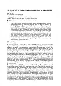
A screenshot of an older version of the CanCoastWatch visualizer is shown in Figure 7.. The visualiser allows the researcher to step through each instant of the simulation run and display the tracks of the targets and platforms together with helpful labels. When new, likely targets are found, it marks their location in the display. Figure 7 displays an instant towards the end of the simulation run. The Aurora has already arrived in the search area and is flying a zigzag search pattern to scan the area for likely targets. The two helicopters have also already arrived. The helicopter from Comox arrived before the Aurora and started to fly a tightly knit zigzag search pattern. However, after the Aurora had arrived and found likely targets, the helicopter abandoned its search pattern and flew to investigate the likely targets. To do this it started a spiral search pattern around the reported location of the new target. The spiral pattern was abandoned the moment the target was declared false. Finally, the second helicopter arrived, and both shared the task of verifying likely targets thereby speeding up the search significantly. 6.2 Non-Cooperative Search In contrast to the first vignette, this vignette features targets that don’t want to be found. It involves a freighter carrying illegal immigrants, which are off-loaded to zodiacs. This scenario features deceptive maneuvers and potentially intentionally false sensor data, and thus requires a sophisticated DIF and an evolution of the RM capability over that used for the 1st vignette. The mission focuses on a threat situation that develops off the northwest tip of Vancouver Island. A freighter coming from the eastern Pacific carrying illegal immigrants arrives near Cape Scott on northern Vancouver Island. It leaves a known sea-lane off Cape Scott to begin a manoeuvre to off-load the illegal immigrants. It does not use the Automatic Identification System (AIS) to identify itself, rather - when it suspects it is being watched – it may use an AIS identification of another freighter scheduled to be in the area, in an attempt to confuse surveillance. It uses two landbased zodiacs to offload the illegal immigrants, by making multiple trips to/from the freighter to ferry persons to the
Proc. of SPIE Vol. 6974 69740E-9
coast. The intended drop point is either Guise Bay or Experiment Bight in the Cape Scott Provincial Park depending on conditions. The scenario is mapped in Figure 8.
Figure 8 Map of Non-Cooperative Search Vignette The freighter and zodiacs will attempt various elusive manoeuvres depending on how the situation develops. Among the elusive deceptions to deceive DIF and force RM to re-evaluate plans and schedules are the following options: use a known commercial shipping route (sea lane) to mask its approach among other commercial freighters; fail to provide an AIS identification or provide a false AIS corresponding to a scheduled freighter known to be scheduled to be in Cape Scott area around this time; depart from a known commercial sea lane through Scott Channel when it approaches the intended drop point for its illegal cargo; use the deceptive cover of the presence of fishing boats fishing off Experiment Bight to “hide” its presence amongst those boats; respond to surveillance by active sensors (radar) by moving back into the commercial shipping route heading away from Vancouver Island; use elusive maneuvers to periodically leave the fishing fleet to rendezvous with the two island-based zodiacs. The complexity of the non-cooperative search is captured by a network of evidence with multiple possible confirmatory patterns. For example, DIF may fuse information from various sensors on various platforms to identify a smugglingoperation by: •
Identifying an isFerrying activity that in turn requires confirmation of isLargeShip(s1) AND isShipNearShore(s1) AND isMovingSlowly(s1) AND isSmallShip(s2) AND isMovingBetweenBeachAndLargeShip(s2,b,s1). • Identifying an isRendezvousing activity that in turn requires confirmation of isLargeShip AND isSmallShip AND isTandemMotionBetweenShips where the tandem motion is defined by isShipsHaveSameHeading(s1,s2) AND isShipMovingSlowly(s1) AND isShipMovignSlowly(s2) AND areNear(s1,s2) The reasoning here will require working through threads of evidence where, depending on the situation, when a resource arrives, what can be sensed, etc. there will be different pathways through the evidence to make the conclusion isSmuggling. The resource management is also complex. The supreme command center in Comox receives a vague hint that a smuggling operation is to commence somewhere in northern Vancouver Island. This is modeled in CCW as a commander node receiving a goal to search for a smuggling operation. Given the large size of the area, and the resources available, the commander node decides to split the search area into two large, independent sub-areas. This is modeled as two sub-goals, each being sent to a separate squadron-leader node. Each squadron-leader node in turn, generates a detailed search plan for the resources under its control, and sends tasking orders to their subservient nodes. In the process, one of them has to make a decision if an Aurora aircraft that is already on a routine background surveillance mission around Vancouver Island should be ordered to interrupt its mission and participate in the hunt for the smugglers. As usual, the background mission is modeled as just another goal that the deciding node has to satisfy. Later, the other squadron-leader node is faced with the dilemma of satisfying a high-priority request to find a sinking fishing boat while the search for the smugglers is going on. Again, two goals need to be simultaneously satisfied. Depending on the situation and on the resource availability, different decisions will be made by the nodes. A screenshot of a more recent version of the CCW Visualizer for the just described scenario is given in Figure 9.
Proc. of SPIE Vol. 6974 69740E-10
The test bed allows the evaluation and comparison of different fusion and resource management algorithms with respect to several criteria, for example, the elapsed time until the sinking fishing boat or the smuggling operation is discovered. Other criteria include the cost for the surveillance operation, or the weighted sum of the detection time and the cost of the operation.
IL Jul
V CunCoustWutch
File View
Si mulation complete
Viewer Controls Pan
Zoom
+
5
++
Vignette
+
Cape Scott
Node and Track Display Options 2
Draw
Past Present Future
Labels
Comms Sensor
EnDED
EEEE EnDED
DDE LI LI
Display
nteasMessages GIS
LatjLong
Utility Functions
Refresh Brighten
i6:th:ot Configuration Editor
16:16:00
16:08:00
Trajectory Editor
16:24:00
16:32:00
440:00
Darken
Play Rewind Loop
Relationship Editor L Batch Run View I CanCoast Watch - Vignette Viewer
Figure 9 Screenshot of Non-cooperative vignette. The cyan colored objects indicate planned and actual tracks of friendly surveillance resources. The smuggling tanker and zodiacs are in red. Neutral ships are in white.
Proc. of SPIE Vol. 6974 69740E-11
7. CONCLUSIONS This paper described the current status of the CCW test bed. When completed, CCW will provide a flexible multi-agent architecture that allows researchers to test dynamic resource management, distributed data fusion, and dynamic resource management algorithms in a setting that is realistic enough to draw valid conclusions about the effectiveness of netenabled large area costal surveillance applications. We hope that CCW will be a useful tool for military researchers.
REFERENCES 1
Pierre Valin, Adel Guitouni, Éloi Bossé, Hans Wehn, Richard Yates, Harold Zwick, “Testbed for large volume surveillance through distributed fusion and resource management", SPIE Defense & Security Symposium, Orlando, Florida, USA, April 9-13, 2007 2 Hans Wehn, Richard Yates, Pierre Valin, Adel Guitouni, Éloi Bossé, Andrew Dlugan, Harold Zwick, "A Distributed Information Fusion Testbed for Coastal Surveillance", Fusion 2007, Quebec City, July 9-12, 2007 3 Col. John R. Boyd, Patterns of Conflict, December 1986 4 J. Roy, É. Bossé, Sensor Integration, Management and Data Fusion Concepts in a Naval Command and Control Perspective, DREV-R-9816, Oct. 1998 5 Roozbeh Farahbod, Uwe Glaesser, Hans Wehn, “Dynamic Resource Management for Adaptive Distributed Information Fusion in Large Volume Surveillance”, SPIE Defense & Security Symposium, Orlando Florida, March 1820, 2008
Proc. of SPIE Vol. 6974 69740E-12