Sequence Representation and Analysis. Kiam Tian Seow and R. Devanathan, Senior Member, IEEE. Abstruct- A unifying temporal logic framework is proposed.
IEEE TRANSACTIONS ON ROBOTICS AND AUTOMATION, VOL. IO, NO. 2, APRIL 1994
220
A Temporal Framework for Assembly Sequence Representation and Analysis Kiam Tian Seow and R. Devanathan, Senior Member, IEEE
Abstruct- A unifying temporal logic framework is proposed for modelling, specifying, and analyzing mechanical assembly sequences. Propositional temporal logic of Manna and Pneuli is the assertion language used for representing and analyzing all constraints or conditions that assembly sequences must satisfy. The generalization of the existing representations through the proposed framework is demonstrated. A new concept of reverse-equivalence, relating assembly and disassembly forms of knowledge, is introduced. It is shown that existing and new assembly sequence properties can be formulated and rigorously proved via mechanical theorem proving based on two assembly process-axioms, and the language inference rules and theorems. Comparison of the proposed framework with the existing representation schemes highlights the main strengths of the proposed framework, viz., temporal expressiveness, strong mechanical manipulation capability and precise formalism. The implementation of the framework on an IPC SUN SPARC workstation using Quintus Prolog for automatic generation of assembly sequences is described. A simple example illustrates the use of the proposed framework for representation, evaluation and selection of feasible assembly sequences.
I. INTRODUCTION
A
SSEMBLY PLANNING plays a fundamental role in the manufacture of most mechanically assembled products. In this paper, we are concerned with the assembly sequence representation issue. An implicit assembly sequence representation refers to the conditions or constraints that assembly sequences must satisfy. With a growing need to systematize and computerize the generation of correct and complete assembly sequences [ 11, it has become increasingly necessary to address the related problem of completeness and manipulability of representation. There is a need to develop a formal framework that can completely and compactly represent the assembly sequences, and provide an inference mechanism to efficiently facilitate the analysis of complex precedence relationships which are invariably involved. One such development is Fox’s language [2] for implicit representation of serial robotic tasks. Implicit representations have also been formulated as “establishment conditions” (first introduced by Bourjault [3]) and “precedence relationships” by Homem de Mello and Sanderson [4], “liaison precedence relationships” by De Fazio and Whitney [ 5 ] ,“MPO and NL()” predicates by Huang and Lee [6] and “assembly constraint” by Ayoub and Doty [7]. Except for the “establishment conditions” scheme, the other schemes are quite similar, differing only Manuscript received December 1 1 , 1992; revised July 29. 1993. The authors are with the School of Electrical and Electronic Engineering, Nanyang Technological University, Nanyang Avenue. Singapore 2263, Republic of Singapore. IEEE Log Number 9215780.
in the degree of formal treatment and the notation of the precedence symbols used. In general, as shown later, these schemes suffer from the lack of expressiveness to assert a wider vocabulary of precedence ordering constraints, as well as an adequate inference mechanism to facilitate concise and insightful analysis over the representations. The feasibility of assembly sequences depends not only on the geometric or inherent ordering constraints [8] (also called hard constraints’ in Huang and Lee [6]),but also on the softconstraints (also called planner directives in Ayoub and Doty [7]) that specify additional precedence requirements based on non-geometric criteria. The nature of the soft constraint is such that it can be used in decision making by the designer to narrow down the choice to a few “good” sequences from among the possible assembly sequences [9]. The designer may choose to apply the soft constraints along with the hard constraints before generating the assembly sequences, or he may defer his decision to apply the soft constraints until after all the assembly sequences are generated based only on the hard constraints. Existing techniques to find the appropriate sequences include an algorithmic search over a graphical representation such as the AND/OR graph [ lo], using admissible heuristics of some evaluation criteria [l 11. However, such an approach may not provide sufficient mechanical manipulability and not much insight can be gained from the selected sequences. In Baldwin et al. [9], [12], evaluation and selection are done by manual editing via computer-guided instructions and criteria options. In Henrioud and Bourjault [13], the assembly constraints are classified and formalized. In Delchambre [ 141, all temporal constraints are specified by a single predicate precedenceorder() only. A temporal logic framework unifying all the implicit representations, upon which they could be precisely described and therefore mathematically reasoned upon, so as to generate the desired assembly sequences, is proposed in this paper. We present a temporal logic formulation of assembly sequence properties that forms the basis for analyzing assembly sequences. Propositional temporal logic of Manna and Pneuli [ 151, [16] is adapted for the purpose. The proposed framework standardizes the representation of the elements of precedence knowledge that could model the hard constraints. Table I shows the various symbolic representations, as used by previous researchers, that correspond with those asserted ’In our work, the term hal-d-ronsrrainr is used for precedence constraint due to part geometry. It is strictly essential and invariant for a given assembly, hence the term “hard”.
1 O42-296X/94$04.00 0 1994 IEEE
221
SEOW AND DEVANATHAN: A TEMPORAL FRAMEWORK FOR ASSEMBLY SEQUENCE REPRESENTATION AND ANALYSIS
VARIOUS PROPOSED
No.
Operator name
1 2
Precede Until
'We use the symbol
"5" in
TABLE I REPRESENTATIONS OF ASSEMBLY TASK-PRECEDENCE
Proposed framework
M P b i ,pa) NL(?ji ~ 2
Pl P P 2 P2UP1
place of the symbol
Symbolic representation as used in Huang [6] Homem de Mello [4] Ayoub [7], Fox [2]
"+"used
1'1 < P 2 P1
)
I P2
De Fazio [SI
PI < P 2 -
P1 3
PZ'
-
in [ 5 ] so as to avoid conflict with the logical implications connective used from
Section 11-Bonward.
by two temporal operators. Except for Huang and Lee [6], no apparent attempt is made to formally derive the assembly sequence properties. This is largely due to the lack of mathematical support for mechanical manipulation of these knowledge elements. The use of temporal logic can not only extend the knowledge forms beyond these two elements, but also can provide the inference mechanism for mechanical derivation of many useful properties, including those provided by Huang and Lee [6]. By virtue of its wider set of temporal operators and established rules and theorems providing the strong manipulability, it could possibly provide a flexible framework by which design constraints (both hard and softconstraints) could be specified and logically integrated to obtain the desired or feasible set of precedence specifications. It should be pointed out, however, that it appears difficult to specify a correct and complete set of hard constraints for complex assemblies. This difficulty is regardless of the form of representation used including our proposed framework. Essentially, there have been two broad approaches to the generation of hard constraints. The approach due to Bourjault [3] and De Fazio and Whitney [5] lends itself to interactive systems. The second approach is to generate the hard constraints through an algorithm operating on a graphical model of the product assembly [6], [17]. However, the physical and geometric reasoning required for determining the constraints appears quite complex and are themselves active topics of further research [ 171. The paper is organized as follows: Section I1 presents the necessary background for the use of temporal logic as an assembly constraint language. Section I11 presents a temporal formulation of the sequence behavior. Section IV discusses the general framework for assembly modelling, specification and analysis. Section V presents the software implementation for automatic assembly sequence generation and verification. Section VI provides an illustrative example. Section VI1 compares and discusses the proposed framework with existing representations. Section VI11 summarizes the paper.
or not done) of the different tasks. Any transition between two distinct states corresponds to the carrying out of the operations of the task involved. The states are identified with the nodes and the transition between states by edges of a graph representing the assembly process. A given assembly sequence can then be identified in terms of a subset of nodes, put in a particular sequence, defining a path in the graph. Our view of the assembly plan is similar to that used by Huang and Lee [6] and De Fazio and Whitney [ 5 ] .
B . MAPS and Temporal Logic Linear time temporal logic is essentially a language for describing sequences of situations and for reasoning about them. In a purely temporal interpretation, a sequence of situations represents the evolution of the state of the world with time. By considering an interpretation where the sequence of situations represents the successive discrete states an assembly goes through to be assembled from its various parts, we could use temporal logic for assembly sequence representation and analysis. Suppose there are exactly n tasks for a product assembly. Then the status of these tasks (that is, whether each task is done or not) at each stage where some task(s) just begin execution constitute an abstract state of the assembly or disassembly process. By viewing all such possible states, a total of 2" of them, as the problem space, the process of assembly or disassembly becomes a process of state-transitions in this problem space. The knowledge about product assembly or disassembly becomes that of state-transitions. We will now formally introduce the problem space before defining some temporal operators that can be interpreted by the statetransitions in the next section. A mechanical assembly planning structure (MAPS) for an assembly is the problem space that completely encompasses all feasible assembly sequences and can therefore be formalized as a 2-tuple model M given by
M = ( S , R ) . where 11. BACKGROUND
A . Assembly In our formulation, the assembly process for mechanical assemblies is assumed to consist of well-defined tasks all of which when executed, will result in the assembled product. Each task is assumed to consist of a set of operations in which one or more of the connections (or liaisons) between parts of the assembly are established. The states of the asnemblv mocess are remesented in terms of the status (done
S is a finite set of states of true atomic propositions of distinct assembly tasks {pl,p p , . . . .p,} that constitute the whole assembly. 2) R is a binary relation on S ( R C S x S).which gives the possible transitions between states and must be total,* that is, VJ E S 3.y E S 1 (.r..y) E R. 1)
'Being "total" is required to ensure a complete state-transition space with no isolated states.
-
IEEE TRANSACTIONS ON ROBOTICS AND AUTOMATION, VOL. 10, NO. 2, APRIL 1994
222
MAPS is a simple Kripke structure [18] or state-transition graph M of discrete states with only assembly task-symbols and without any global constants3; and any finite list of states or finite trajectory 0 E M is a possible assembly sequence. Propositional temporal logic [16] is a language of propositional logic augmented with temporal operators to facilitate reasoning over the space of sequences of states. The logical “AND,” “OR,” “Negation,” “Implication,” and “Equivalence” connectives in classical logic are denoted by the symbols A,V, 1,+ and H or E respectively. The sum and product symbols denote a string of logical “OR’ and “AND” operations respectively. Temporal operators include Always 0,Eventually 0,Next 0, Until U and Precede P. A logic formula w containing at least one such operator is called a temporal formula. An interpretation, in the context of assembly, refers to a possible assembly sequence of the defined problem space that “interprets” (that is, makes true or satisfies) the temporal formula describing some assembly precedence constraints. The suffix of a sequence refers to its partial sequence that begins from a given state. Before defining the temporal operators in terms of the satisfaction relations, the formal notions of a general interpretation and its suffix are first given. Definition 1 [Interpretation I ] : An interpretation I is a 3tuple (M,G, a), where a is a temporal sequence of states in structure M ( a = so - s , - s2 - . ’ .) and G4 assigns a value for every global constant in M . With the above definition of Interpretation, the structure M can therefore be regarded as a restricted class of possible semantics or interpretations ( M ,a) of temporal logic TL [16] by which precedence and other state constraints J E TL can be specified to define the set of correct and complete assembly sequences or desired sequences M J c M . Definition 2 (Susfix): For IC 2 0, the k-truncated s u m of a temporal sequence a = so - s1 - s2 - . . . (written: a(k)) is the sequence s k - s k + l - s k + 2 - . . .. I ( k ) is the interpretation obtained from I , by replacing a with dk). Now, for all interpretations I , we say that I satisfies w (written: b’ w ) where the satisfaction relation is defined inductively on formulae as follows: +‘wl v w2 iff k’w1 v t=’w2 b’wl A w2 iff +‘tul A k’w2 iff Tb’w +‘ow iff for all IC 2 0, k’(‘)w. b ’ o w iff there exists a IC 2 0 such that b’(”w. iff +‘“)tu. b’wlUw2 iff there is a IC 2 0 such that b’(k)w2 and for all i , 5~i < IC,+‘(‘)wI. ~ ‘ W ~ PiffUT Ik ’~l w 1 ~ w p Any formula that is not qualified by a temporal operator is assumed to be true only in the initial state S O .
(E)
(n)
~
‘
T
w
+‘ow
B. Disassembly and R-Equivalence In assembly sequence planning, two basic approaches are adopted to generate assembly sequences-the assembly and disassembly methods [6], [8]. Establishing transformation properties between assembly and disassembly forms of knowledge motivates the concept of R-equivalence. First, we introduce the notion of reverse-interpretation. Definition (Reverse-lnterpretation I): Given an interpretation I, its reverse - interpretation 7 is a 3-tuple (M,G,F),where 8 is an exact reverse of a such that is similar to M except that all its transitions reverse directions. Note that for a given assembly, M is defined and known. An assembly interpretation (denoted by I d ) can therefore be simply written as a, and a reverse-assembly or disassembly interpretation (denoted by Id or 1,) can be written as a. 1 ) R-equivalence: Given two symbolic logic functions (formulae) of precedence knowledge, F = ~ ( P I , P ~ , P ~ , and ...G ~ P=~ g(Pi,Pz. ) P ~ , . . ’ , P Twhere L)~ p l l p 2 , p 3 , . . . , p , are logic variables, G is said to be R-equivalent to F if and only if, for all I,
k’
F =+‘G
(1)
Definition 4 (Sequence-lnvariance): A temporal logic formula H is said to be sequence-invariant if, and only if, for all
I,
kI H +T
H
(2)
Clearly, a sequence-invariant H is R-equivalent to itself and the following theorem dictates that the set of H is not empty. Theorem 1 (Invariance Theorem): A temporal logicformula H is sequence-invariant if it is a simple logic combination of terms, each of which is of the form O Q or o Q , where Q is any classical state-formula (i.e., without temporal operators). 4 Proof: see Section I X . A sufficient condition for the formula F to be R-equivalent to formula G is that there exists a sequence-invariant H such that for all I ,
1’( F
H)
(3)
(G = H )
(4)
and
b’
Hence, if we could “discover” any sequence-invariant H such that (3) and (4) hold for I = I d , we have in fact found one transformation property between assembly and disassembly. Since assembly tasks are not necessarily reversible, the Requivalence of the assembly and disassembly methods will hold only if each task used in disassembly is the inverse of a feasible assembly task, regardless of whether this inverse task is itself feasible or not. The term “disassembly task” therefore refers to the logical inverse of a feasible assembly task. 111. TEMPORAL FORMULATION OF TASK-SEQUENCE BEHAVIOUR
3Global constant: Assigned variable which remains constant over the finite list of states or trajectory. Our assembly interpretation does not require any global constant. The Etuple has been introduced only for a more complete definition of Interpretation.
An assembly process-task (or simply, assembly task) refers to an exclusive abstract entity whose execution results in the involved assembly parts being installed in their final relative
SEOW AND DEVANATHAN: A TEMPORAL FRAMEWORK FOR ASSEMBLY SEQUENCE REPRESENTATION AND ANALYSIS
positions. Before stating the state-theorems and process axioms for assembly and disassembly, some important terminologies are first defined. Definition 5 (Assembly process task-symbol): It is a boolean or logic variable p that indicates M’hether an assembly task it represents has been done or not. A more general term to assert the DONE status of a group of tasks is given by the following definition. Definition 6 (Assembly process task-formula): It is any formula P that contains at least one assembly process task-symbol and satisfies the following conditions: 1) It does not have any connecti1.e. 2 ) It does not have any temporal operators.
and hence it is called the task-liveness property. Collectively, these properties imply that every assembly task must be done once and only once. Together with the NOR theorem, these two axioms form a general axiom set5 or domain A which characterizes the fundamental nature of assembly sequences. A logical reverse of the assembly process is the disassembly process, characterized by the general set D,which is defined by the AND theorem and the following “reverse” axioms:
D P X l :t- 0 ( 7 P + O i P ) DPX2 :F o -P
”7”
Therefore, an assembly process task-formula is a simple logic expression, in positive form, of As and Vs only, relating the process task-symbols.
Now, by T80 in Section X of [19]:
t- 0 ( P + U P ) A 0 P
APCX :t- -PUO P Intuitively, APCX may be paraphrased as “ P is not true (or done) until an eventual state when it becomes true and remains so in subsequent states of the assembly process.” By replacing P in ( 5 ) by 7 P , we have the following “condensed” axiom for disassembly:
DPCX :k PUO 7 P
n
c p z = False 1=1
2) Final state-theorem (AND Theorem): In the final state of any assembly sequence, all assembly tasks are done, that is: 71
n p l = True 1=1
Note that in the disassembly process, the AND theorem becomes the initial state-theorem and the NOR theorem becomes the final state-theorem.
B . Process-Axioms Suppose P is any assembly process task-formula. Then:
A P X l : k 0 ( P + 0P ) (Task-persistence property) APX2: F O P (Task-liveness property) Intuitively, APXl may be paraphrased as “whenever P becomes true in an assembly process state, it will always remain true in subsequent states of the assembly process.” APX2 may be interpreted as “there is a future assembly process state in which P is true.” APX 1 and APX2 are necessity properties. APX 1 constitutes a necessary condition that for process efficiency, in robotic assembly for example, every assembly task, once done, should not be undone or redone at all throughout the rest of the assembly process. The “DONE” status of every assembly task should persist, hence it is called the task-persistence property. APX2 constitutes the nature of the assembly process in that every assembly task should eventually be executed for a complete assembly. This is “something good” that must occur,
lpunp
Thus the “condensed” axiom for assembly is:
A. Process State-Theorems
Let ( p 1 . p ~ .. . . . p n } be a set of 71 distinct process tasksymbols that constitute the whole assembly. Let no two task-symbols correspond to the same assembly task. 1 )Initial state-theorem (NOR Theorem): In the initial state of any assembly sequence, all assembly tasks are not done, that is:
223
Intuitively, DPCX may be paraphrased as “ P is true until an eventual state when it becomes false (or undone) and remains so in subsequent states of the disassembly process.” With these fundamental axioms, we may formally define an assembly process-state, a legal assembly sequence and its corresponding disassembly sequence as follows: Definition 7 (Assembly process-state): It is a discrete instance s , E S that assigns to eL1ery task-symbol a true or false value to indicate whether the assembly task it represents is done 01-not done, respectively. It is discrete in that it is the instance at which some m tasks, where m 2 0 , begin execution and no other task is being executed. Definition 8 (Legal assembly interpretation I A or sequence 0): (T is any finite sequence of different accessible assembly process-states that obeys the assembly process-axioms and can be represented in the following general form: ,yo -
s,
-
,sa - . . . - s,, .where n is an integer 2 0.
so is the initial state where all assembly tasks are not done (ie, all task-symbols (p,) are false) and s,, is the final state where all the assembly tasks are done (ie, all task-symbols (p,) become true).
Definition 9 (Legal disassembly interpretation I D or sequence c): Given a legal assembly sequence (T, the corresponding disassembly sequence 3 obeys the disassembly process-axioms, and with respect to the different accessible assembly processstates, is given by:
-
s, -
S,,-I
- . . . - sa - s1 - s o . where n is an integer
20
s,, is the initial state where all assembly tusks are done (ie, all task-symbols ( p , ) are true) and so is the final state where all 5General axiom set: Axioms that apply to every task-symbol.
IEEE TRANSACTIONS ON ROBOTICS AND AUTOMATION, VOL. 10, NO. 2, APRIL 1994
224
the assembly tasks are undone (ie, all task-symbols ( p , ) become false). In task-sequence planning for a manufactured part or assembly, any sequence that is not legal need not be considered further because it is either not process efficient or it will not result in a complete assembly. Using the process-axioms, many assembly sequence properties could be proved via mechanical theorem proving using well-established rules and theorems of temporal logic. See Section B for the assembly sequence properties. The first 12 properties, APT1-APT12, correspond to Huang and Lee’s [6] results but proved using temporal logic theory as originally demonstrated in Seow and Devanathan [19], [20]. The two transformation properties, APT 1 and APT 2, are derived by applying the concept of R-equivalence and Invariance Theorem as shown in Section X.
Iv. REPRESENTATION AND ANALYSIS A. The Temporal Framework
In our application, we are strictly reasoning in the assembly domain A in which any legal sequence, if represented as an ordered list, is a sequence of all defined task-symbols that appear once and only once. This is a symbolic view of a legal sequence that conforms to the assembly domain A. Therefore, it is sufficient to specify the model-characteristic temporal constraints6, with the convention that every task that constitutes the assembly is not done initially and would eventually be executed, once and only once, without having to explicitly state so. Formally, if f ( p l , p z , .., p , ) is an assembly constraint, where pi is a task-symbol, this implies:
..A l p ,
1 ) Infeasible Assembly States or Subassemblies:
where state; is an infeasible assembly process-state formula. This specification may be paraphrased as “every assembly process-state formula statei, for 1 5 i 5 j , is not true in every state of the assembly process”. 2 ) Feasible Assembly States or Subassemblies:
f i o statei, i=l where statei is a feasible assembly process-state formula. This specification may be paraphrased as “each assembly processstate formula statei, for 15 i j, must eventually become true in some state of the assembly process.” 3 ) Precedence constraints: In general, precedences are described in any of the following forms:
P ~n)’ p i i=l
)
~ [ l p i ~ u p i ]
A f ( p 1 ,PZ , . .
)
pn)
In the assembly domain A, unless otherwise stated or implied, any assembly property or constraint P is simply written as k P or P instead of kd P. We also use the convention that:
where X and Y are any appropriate temporal logic formulae. Such a representation scheme, with built-in expressiveness as demonstrated, enables many temporal constraints to be described, limited only by the experience of the designer.
C . Analysis: Selection by Logic Integration
Given that ‘FI is a temporal formula of minimal ordering or geometric constraints [2] inherent to a given assembly, M n c M describes the largest set of all and only possible assembly P = U l P i A [ ’ p i ~ u ~ i l ~ f ( p l : ~ z , . . . r ~ n ) sequences. i=l Suppose a user-specified soft-constraint formula S corresponds to M s , then ‘FI A S would correspond to the desired Where assembly and disassembly precedence knowledge apM x , a set obtained by the pear in an expression, the former will be prefixed by kd and (or feasible) sequences M ~ A s intersection of the two sets M n and M s ; that is: the latter, FD, unless it is obvious from the context.
pd = f ( p l r p 2 ,. . I & )
(”
if, and only if,
)
B . Implicit Representation Scheme Given an assembly which can be completely connected by a set of n distinct assembly tasks {PI,p z , ...,p , } , an assembly process-state formula statei asserts a particular assembly state, and is a simple logic function of As only, involving all the Model-characteristic constraints: specific assembly constraints to be satisfied by any LEGAL sequence of a particular assembly for feasibility.
Logic integration refers to the A operation of ‘FI and S to obtain J’ (that is, J’ = ‘FI A S). By applying the assembly sequence properties, it is possible to obtain a more compact representation for J . M ~ A scan be directly computed by using the derived assembly sequence properties and the automaton model of t-* p j P p k , as presented in the next section.
SEOW AND DEVANATHAN: A TEMPORAL FRAMEWORK FOR ASSEMBLY SEQUENCE REPRESENTATION AND ANALYSIS
225
TABLE I1 SYMBOL REDEFINITIONS Symbolic representations in No. Theoretical framework
Practical Framework
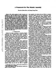
Fig. 1. Automaton for the satisfaction relation of kd ? ) J P p k ,where p , and are assembly task-symbols.
V. SOFTWAREIMPLEMENTATION Based on the theoretical framework, a simple verification and synthesis tool, called the Mechanical Assembly Sequence Satisfiability Checker (MASS-C), has been built using Quinrus PROLOG [21] on the ZPC SUN SPARC workstation. The temporal operators are implemented as logic predicates (see Table 11, redefinition), where L-X is a symbolic prefix list notation for the formula X so that for any assembly, the formulated temporal formulae, asserting the acquired assembly constraints, can be directly coded as a logic program of the respective predicates. Auxiliary predicates (ver$y() and generate()) are implemented to verify or synthesize all assembly sequences MR,,S that conform to this logic program of assembly constraints 'FI A S . The current MASS-C is built based on the definition for P and the properties APT 4, 6, 8, 10, 15 and 16 (see Section X), using recursion [22] as the basic design strategy, with the list structure for representing the explicit assembly sequences, both serial and parallel, as well as the assembly process task-formula in prefix list form, since list is well-suited for PROLOG recursive programs. As an ordered list of tasks, a parallel or concurrent sequence has at least one member which is a list subset containing 2 or more task-symbols representing concurrent tasks. A serial sequence is just an ordered list whose members are single task-symbols. Using these properties, a useful class of temporal expressions for assembly application can be expressed in terms of the basic element p j p p k . Therefore, the finite state-graph structure or automaton for the restricted satisfaction relation of this basic expression, as shown in Fig. 1, suffices for our implementation purpose. It forms the basic underlying invariant structure upon which MASS-C is built. To interpret the structure, consider any finite sequence CT of discrete assembly process-states whose tasks include 1lJ and p k . If CT starts in node 40, traverses along the transitions, and ends in the accepting node q 2 , represented by a double concentric circle, it is said to satisfy this basic assembly constraint p J p p k . The reader is referred to Seow [23] for actual implementation details. The implementation has been carried out using the generate and test (GT) paradigm [24]. In this paradigm, each possible combination of assembly tasks is systematically generated and then tested to see if it satisfies the integrated constraint 'FIA S by using recursively the satisfaction relation of the basic constraint mentioned above. In order to find the serial assembly
CAP
STICK
RECEPTACLE
HANDLE
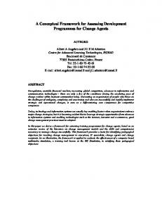
Fig. 2. A simple product in exploded view.
sequences, the number of combinations considered by this method is the size of the Cartesian product of the domains of all the task variables. For a serial assembly sequence consisting of 71, tasks, the domain size of each task variable of the ordered list decreases uniformly as n, ( n - 1):. . ., 1along the sequence. Hence the total number of combinations to be considered is n!.However, more computationally efficient methods exist for solving the problem. For example, given a constraint p l P p 2 , instantiation of the task symbol p2 to the 1st task variable will result in an immediate failure of the combination in satisfying the constraint. More generally, those combinations that instantiate the symbol p2 to the ith task variable will fail when a jth task variable is instantiated the symbol p l in an ordered list where z < j for all instantiations of the kth task variables for ,i < k < j. Using a certain algorithm for propagating the constraints to the domains of the different task variables, efficient search techniques for the constraint satisfaction problem result [24]. For a uniform domain size d for each task variable, and the total number of binary constraints (between two task symbols) being e, the worst case complexity of the algorithm is O(e x d 2 ) .
VI. EXAMPLE An exploded view of the assembly taken from [ 101 is shown in Fig. 2 . This example is chosen because it is simple and so does not obscure the illustration of the analysis. It also facilitates comparison with the AND/OR graph representation [IO] as discussed under Section VII. Three distinct assembly tasks to be performed are defined as given below: 1) p l : screw task, connecting CAP and RECEPTACLE. 2 ) p 2 : screw task, connecting RECEPTACLE and HANDLE. 3) p 3 : insert task, connecting RECEPTACLE and STICK.
226
IEEE TRANSACTIONS ON ROBOTICS AND AUTOMATION, VOL. IO, NO. 2, APRIL 1994
A. Hard-Constraint Specification
Therefore.
The geometric constraint 3-1 that the stick must be in the receptacle before both ends are attached is expressed as follows:
3-1 = (1Pl A 7P2 A
733)
A (’PlUUPl
A 7P2UnP2 A 1P3UuP3) A P3p(Pl A P2)
where the model-characteristic hard constraint E d is: xd = P3p(Pl A P2)
=~
3 %
V P ~ Pby P APT8 ~
The following is an enumeration of the serial (No. 1 4 ) and parallel (No. 5-7) sequences in M H . The notations [Pi,pj] and < pirpj > represent that the tasks pi and p j are done sequentially and in parallel, respectively. Sequence Number
1
bll P37 P21
2 3
b2.P3r
6
7
Pll
b3> Pl P21 b3r P2r PI1 b3r < Pl7P2 >I 1
[< PllP3 >rP2] [< P27P3 > ; P l ]
0l ( l p 1
=
0
= (PZPPI)A (P2pP3)
and
The only sequence selected is sequence number 2. Similarly, case 3 results in the selected sequence 1 only. For case 4, in short-hand notation, JAG = % A A SG -
- (P3PPl V P3PP2) A
PI A ~
P AZ P ~ )
= ( P ~ ~ PAZ( -) P 3 u P l ) V ( P 3 P P l ) A ( y P 3 u P 2 ) by Case 1
This means that:
B. Sof-Constraint Specification =
S2
Sequence Ordered List
4 5
1.
By considering the two sum of product (SOP) terms, the set of selected sequences, MH,,s, contains those in M x with sequence numbers 1, 2, 6 , and 7. By a similar reasoning , for case 2, S 2 is simplified to:
A 7 ~ A2p3) (1Pl A 7P3 A P2) S3 = PlPP3 SI specifies that the assembly process-state ( 7pl A 7 3 2 A p3) must not appear in the sequence, S 2 specifies that (-yl A 7p3 A p2) must be one of the assembly processstates in the sequence, and S3 specifies that pl must precede p3 in the assembly sequence. 4. S1 is to be executed serially only as in the following specification:
2. 3.
S2
S = (PlpP2 v P 2 p P l )
A (P2pP3 vP3pP2)
A (PlpP3 v P3pP1) A S 1
which in shorthand notation can be written as:
SC = 07(-71)1 A 7p2 A p s ) , where G = PaPPb V pbPp,. and p a . Pb are distinct C. Logic Analysis: Integration and Simplification Assembly sequence properties derived (see Section X) are applied to simplify the integrated specifications JA which could result in a more compact representation. For case 1:
S1 =
T(1Pl A 7P2 A P3)
= 0 ( 1 ~ V3 (p1 V p2)) -’P3U(Pl v P2)
(lP3UPl) v (lP3UP2)
by DeMorgan’s Law by AFT15 by AFT 5
D . Automatic Generation and Verification Using MASS-C, explicit assembly sequences can be automatically generated or verified based on the given constraints. The logic program segment for the hard constraint 3 - 1 ~is given by: hard-constraint:precede (p3, [and, p l , ~ 2 1 ) . and that for the soft-constraints S , say S = SIA&, is given by: soft-constraint:alwaysdot ([and, [not-and, p l , p21, ~311, /* Infeasible assembly state */ eve([and, [not-and, p l , p31, ~ 2 1 ) . /* Necessary assembly state */
’“PR” stands for “Propositional Reasoning.”
SEOW AND DEVANATHAN: A TEMPORAL FRAMEWORK FOR ASSEMBLY SEQUENCE REPRESENTATION A N D ANALYSIS
d
221
\
/nil
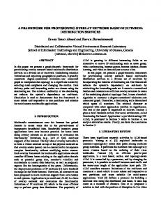
Fig. 4. A solution tree of the AND/OR graph (for Fig. 2) corresponding to more than one assembly sequence. Fig. 3 .
A solution tree selected by SS
After successfully compiling the program in the Quintus prolog interpretive mode, we can synthesize or verify the sequences by simply invoking the respective predicates. To synthesize, type generute(Seq). and press >. The PROLOG interpreter retums the serial sequence:
Seq = [ P ~ , P ~ , P ~ I STICK
no In our example, only one serial sequence satisfies the constraints. To verify if the concurrent sequence [< p2, p3 > pl,] satisfies the specified constraints: Type verifL ([< p2, p3 > pl,]). and press >. The PROLOG interpreter retums the answer:
RECEPT
Fig. 5. Graph of connections for the simple product of Fig. 2.
no This means that the input sequence does not satisfy the constraints. VII. COMPARISON AND DISCUSSION In this section, we attempt to reason that the proposed framework can be considered a generalization of the existing representation schemes whose basic elements are as given in Table I. The example of Section VI is used to illustrate the comparisons made. In case 2 under Section VI-C for example, the integration of S2 with using the proposed temporal logic framework yields the enumerated sequence [p2. p 3 . p 1 ] (sequence number 2). This sequence can be represented as a solution tree of the AND/OR graph (Fig. 4 in Homem de Mello and Sanderson [lo]) for the same assembly, as shown in Fig. 3. Qualitatively however, there is no equivalent mechanism in the AND/OR graph representation to “pick” the solution tree satisfying the additional constraint S2. The advantage of such a mechanism is evident for a more complex product than that given in Fig. 2. In the AND/OR graph formulation, it is observed that in assemblies where time-independence and concurrency among some tasks are possible (for example, the solution tree in Fig. 4), the AND/OR graph cannot represent the precedence among these tasks due to additional constraints that prohibit concurrency, without additional constructs which may obscure the elegance of the AND/OR representation [2]. Apparently, some sequences from the AND/OR graph (for example, the solution tree in Fig. 4) are missing in our
enumeration. This is only because we have identified three tasks, viz, p l , p 2 , and p 3 , for the assembly that correspond to the respective connections of the gruph of connecrions model for the product (see Fig. 5). The connections, c1 and c2, are not treated as tasks but contacts established by the assembly process. Also under case 2 in Section VI-C, we see that Sz directly specifies that the assembly process-state described by the stateformula ( ~ pAl 1p3 A 1 1 2 ) is an eventual state of the sequence. If any of the existing schemes such as Huang and Lee’s [6] is used, such a constraint can only be indirectly specified as MP(p2, 111 V p3). This is certainly not a natural and an easy way of specifying a desired assembly state. Such a limitation is magnified in a larger state problem than the simple example considered here, when expressing one or more desirable stateformulae in terms of the MP(). predicate becomes obviously cumbersome. In the proposed framework, property APT16 allows the equivalent precedence constraint to be directly derived from the desired assembly process-state. This means that the framework actually provides a flexible means to specify and analyze the precedence relationships among the assembly tasks involved. A similar reasoning using property APT15 argues for the Always 0 operator as used in SI. Although the serial implicit representations by Fox [2], De Fazio and Whitney [ 5 ] and Ayoub and Doty [7] may actually be modified or extended to logically encompass concurrent sequences, their only “Precede” operator does not offer flexibility of expression. For instance, a simple constraint
228
IEEE TRANSACTIONS ON ROBOTICS AND AUTOMATION, VOL. IO, NO. 2, APRIL 1994
that can be specified only as l ( p 1 < pz), using any of these existing schemes, can actually be re-specified either as l p l U p 2 or its equivalent l ( p l P p 2 ) in the proposed framework. In any case, these existing schemes lack formal treatment in that there is no formal inference mechanism to logically prove the algebraic properties involving their only “Precede” operator. In the above discussion, it is clearly illustrated that the proposed framework generalizes the existing representation schemes. It provides a richer vocabulary of temporal expressions. In fact, it is even possible to specify a more complex formula such as plPp2 -+ o ( S t a t e ) ,which can be intuitively interpreted as “if p l is executed before p 2 in the sequence, then the sequence must contain the process-state State as well.” With a strong underlying logic mechanism of general rules and theorems not found in all previous work, assembly sequences can be mechanically analyzed through the use of straightforward syntactic manipulation of precedence and state constraint formulae. Finally, our framework can also support backward assembly planning. Backward assembly planning is a method of obtaining feasible assembly sequences from feasible disassembly sequences generated [25]. Planning assembly backwards may need to identify the additional constraint for assembly (which can be conveniently classified as soft-constraint in this paper) which is a non-issue in disassembly. Based on a given set of disassembly constraints, we obtain a logic equivalent of the assembly constraints by APT1 and APT2. By identifying and imposing the additional constraints for assembly upon these equivalent assembly constraints, we can obtain the feasible assembly sequences.
VIII. CONCLUSION We have proposed temporal logic as an implicit representation tool and analytical language for assembly sequence planning. The strengths of the framework over existing representations lie in its strong manipulability, temporal expressiveness and precise formalism. As a basis, task-persistence and task-liveness properties that describe the general assembly sequence behavior have been formulated. The R-equivalence concept is introduced, relating assembly and disassembly forms of knowledge. Properties that facilitate reasoning and manipulation of a class of precedence knowledge asserted by P , U , 0 and o operators have been proved. Together with the support for disjunctive ordering, P and U operators form the theoretical basis for modelling or encoding all possible assembly sequences for a mechanical assembly. Enriched with other operators, temporal logic provides a flexible framework for representation and analysis of temporal constraints of assembly tasks arising from criteria such as the geometric, mechanical and stability properties of a given mechanical assembly. Comparison reveals that the existing representation schemes can be generalized, in terms of the precedence elements, as a language subset of the proposed framework. The framework has been implemented on a workstation for automatic generation of serial assembly sequences. The complexity issues of the computation involved have been briefly
discussed. A simple example illustrates the use of the proposed framework.
Ix. A PROOF OF INVARIANCE THEOREM Let Q be any state-formula, 1 be any arbitrary general interpretation (corresponding to a sequence o), and 7 be the reverse interpretation (corresponding to an exact reversesequence 5). Then: l=I
OQ
iff for all k 2 0, + I “ ) Q iff for every state in o,Q,is true iff for every state in 5,Q is true iff for all j 2 0. ~ 7 ” )Q iff bT Q Also :
+=‘OS there exists a k 2 0 such that Q there exists a state in o in which Q is true there exists a state in (T in which Q is true Q there exists a j 2 0 such that +’(’) oQ Hence, by induction, if a temporal logic formula H is any logic combination of terms, each of which is of the form 0Q or o Q,then for all I ,
iff iff iff iff iff
+’
pH
+
H
X. ASSEMBLY SEQUENCE PROPERTIES Assume that P I , P2, P3 are any assembly process taskformulae. All stated theorems Ti are restricted to the assembly domain A and denoted simply as t Ti. Where necessary, Id Ti and kv Ti would be used to denote that Ti is a theorem, restricted to the assembly domain A and disassembly domain V ,respectively. APT 1 t d 7P2UP1 *tv P1U7P2 Proof By D 40 [19]kd 7PzUP1 ti 0 (Pi V 7P2) Similarly: kv P1U7P2 H 0 (1‘1 v 7P2) Note that 0( Pl V 7P2) is a sequence-invariant formula. t d lP2UPl ++Iv PlUlP2 Hence: APT 2 P P,PP, 4 - v 7P1P7P2 Proof By definition: P2PP1 -(-P2UP1) By T5 [16]: 70(PI v 7P2) 0 l ( P 1 v 7P2) I-A 7PZUP1 H 0 (PI v 7P2) By D40 [19]: Negate both sides: kd P2PP1 H o PI V l P 2 ) Similarly: tv l P , P 7 P , 0 l ( P 1 v l P 2 ) o 7(P1V 7P2) is a sequence-invariant formula. Hence: P P2PPl *tv lP1P7P2 APT 3 1 ( l P 1 A iP2)UP3 * 7P1UP3A7P2UP3 APT 4 t (Pi V P2)PP3 * PiPP3VP2PP3 APT 5 t 7P,U(Pl v Pz) 7P3UPlVlP3UP2 APT 6 PsP(P1 V P2) P~PP1AP3PP2 APT 7 t 7P3l!(P1 A P2) ++ 7P3upi A ~ p 3 u p 2 APT 8 E P3P(P1 A Pz) ++ P3PP1 V P3PP2 APT 9 t (TPI v 7P2)uP3 lPlUp3 v 7p2Up3 APT10 k (Pi A P2)PP3 t--f P1PPs A P2PP3
- -
SEOW AND DEVANATHAN: A TEMPORAL FRAMEWORK FOR ASSEMBLY SEQUENCE REPRESENTATION AND ANALYSIS
k lP3~?dP2A lP2uP1 -+ -f’&/pl APT1 1 APT12 t Pipp2 A P2PPs -+ PlPP, t- lPIUP1 APT13 [17] APT14 t l(PlPP1) k lP2UP1 H 0 (PI v l P 2 ) APT15 APT16 I- P2PP1 i+ O (1PI A P2) (181 APT17 t P2PPl 4 -P,UP2 APT18 k l ( P i P P 2 A P2PP1) APT19 k l ( P i P P 2 A P2Pp3 A P ~ P P I ) [I91 t ,PIUP, A P2PPi ++ P2QP1 APT20 APT2 1 p l p p , A p3pp2A p,pp2 c) p l p p , A p3pp2 APT22 k l(PlPP2 A T P I U P ~ ) [20] For the proofs of APT3-APT12, see Seow and Devanathan [201. For the proofs of 3-APT22, see Scow and Devanathan [19]. All proofs may be found in Seow 1231. [2 1 ]
REFERENCES A. C. Sanderson and L. S. Homem de Mello, “Automatic generation of mechanical assembly sequences,” Geometric Modeling for Product Engineering, M. Wozney, J. Turner, and K. Preiss, Eds. New York: Elsevier, 1990, pp. 461-482. B. R. Fox, “A representation for serial robotic tasks,” Ph.D. thesis, Computer Science, University of Missouri-Rolla, 1987. Alain Bourjault, “Contribution ib une approache mtthodologique de I’assemblage automatis& Elaboration automatique des sCquences optratoires.” Thise de Doctorat, UniversitC de BesanGon FrancheComtC, 1984. L. S. Homem de Mello and A. C. Sanderson, “Representations of mechanical assembly sequences,” IEEE Transactions on Robotics and Automation, vol. 7, no. 2, pp. 211-221, April 1991. T. L. De Fazio and D. E. Whitney, “Simplified generation of all mechanical assembly sequences,” IEEE Journal of Robotics and Automation. vol. 3, no. 6, pp. 64M58, 1987. Corrections. IEEE Journal of Robotics and Automation, vol. 4, no. 6, pp. 705-708, 1988. Y. F. Huang and C. S. G. Lee, “Precedence knowledge in future mating operation assembly planning,” Proceedings of the IEEE International Conference on Robotics and Automation, pp. 216221, 1989. R. G. Ayoub and K. L. Doty, “A representation for discrete assembly sequences in task planning,” Proceedings of the IEEE 13th Annual International Computer Software and Applications Conference, pp. 746753, 1989. A. C. Sanderson, L. S. Homem de Mello, and H. Zhang, “Assembly sequence planning,” Artificial Intelligence Magazine. vol. 1 I , no. I , pp. 62-81, 1990. D. F. Baldwin, T. E. Abell, M. C. M. Lui, T. L. De Fazio, and D. E. Whitney, “An integrated computer-aid for generating and evaluating assembly sequences for mechanical products,” IEEE Transactions on Robotics and Automation. vol. 7, no. 1, pp. 78-94, 1991. L. S. Homem de Mello and A. C. Sanderson, “And/or graph representation of assembly plans,’’ IEEE Transactions on Robotics and Automation. vol. 6, no. 2, pp. 188-199, 1990. L. S. Homem de Mello and A. C. Sanderson, “Evaluation and selection of assembly plans,” Proceedings of the IEEE International Conference on Robotics and Automation, pp. 1588-1593, 1990. T. E. Abell, “An interactive software tool for editing and evaluating mechanical assembly sequences based on fixturing and orientation requirements,” Master’s thesis in Mechanical Engineering, M.I.T., 1989. Jean-Michel Henrioud and Alain Bourjault, “LEGA: a computer-aided generator of assembly plans,” Computer-Aided Mechanical Assembly Planning, L. S. Homem de Mello and S. Lee, Eds. Kluwer Academic Publishers, 1991, pp. 341-381. A. Delchambre, “A pragmatic approach to computer-aided assembly planning,” Proceedings of the IEEE International Conference on Robotics and Automation, pp. 16W1605, 1990. Z. Manna and A. Pnueli, “A temporal proof system,” Foundations of Computer Science IV, Distributed Systems: Part 2 , Semantics and Logic, J. de Bakker and I. V. Leeuwen, Eds. Mathematical Centre Tracts 159, Amsterdam, 1983, pp. 163-235. J. S. Ostroff, “Appendix A: Formal overview of temporal logic” and “Section X: Temporal logic theorems and rules,’’ Temporal logic for Real
[22] [23]
[24] [25]
229
Time Systems. New York: Research Studies Press, Ltd., John Wiley & Sons, Inc., Advanced Software Development Series, 1989, pp. 155-171 and 172-183. L. S. Homem de Mello and A. C. Sanderson, “A correct and complete algorithm for the generation of mechanical assembly sequences,” IEEE Transactions on Robotics and Automation, vol. 7, no. 2, pp. 228-240, 1991. E. M. Clarke, M. C. Brown, E. A. Emerson, and A. P. Sistla, “Using temporal logic for automatic verification of finite state systems,” Logics and Models of Concurrent Systems. NATO AS1 series, Vol. F13, K. Apt, Ed. Berlin, Heidelberg: Springer Verlag, 1985, pp. 3-26. Kiam Tian Seow and R. Devanathan, “A temporal logic framework for assembly sequence planning,” Proceedings of the IEEEIRSJ International Conference on Intelligent Robots and Systems, North Carolina, U.S.A., 1992. K i m Tian Seow and R. Devanathan, “Temporal logic formulation of assembly sequence properties,” Proceedings of the IEEE International Conference on Robotics and Automation, Nice, France, 1992, pp. 1208-1 2 13. Quintus Corporation, an Intergraph Corporation, Quintus Prolog Release 3.1.1for theSUN 314, 11: Language andLibrary Manual, February 1991. R. Bharath, PROLOG: Sophisticated applications in Artificial Intelligence, first ed. Windcrest Books, Inc., ch. 1, “Knowledge representation in prolog” and ch. 2, “Lists and recursion: Key examples,” 1989. K i m Tian Seow, “Robotic-task sequence representation and analysis,” Master of Engineering (M.Eng.) Thesis, School of Electrical and Electronic Engineering, Nanyang Technological University, Singapore, June 1992. Vipin Kumar, “Algorithms for constraint-satisfaction problems: A survey,” Artificial Intelligence Magazine, vol. 13, no. 1, pp. 3 2 4 4 , 1992. S. Lee, “Backward assembly p!anning with DFA analysis,” ComputerAided Mechanical Assembly Planning. L. S. Homem de Mello and S. Lee, Eds. Kluwer Academic Publishers, 1991, pp. 341-381.
Rajagopalan Devanathan, (M’8GSM’91), received the M S c and P h D degrees in Electncal Engineenng from Queen’s University, Kingston, Ontano, Canada, in 1968 and 1972 respectively, Pnor to that, he obtained his M.E. (Power) and B.E. (Electncal Technology) degrees from the Indian Institute of Science, Bangalore, India, in 1964 and 1962, respectively, and B Sc degree from the University of Madras, India, in 1959 He has served in the govemment of India in the areas of planning and technology development in the fields of mass and space communications and the oil & gas industry He has also developed and taught courses in control engineenng relating to the Petroleum industry Since 1983 he has been with the School of Electncal and Electronic Engineering, Nanyang Technological University, Singapore. His current interests are in intelligent tuning, robotic assembly, control theory and applications Dr Devanathan has served as the General Chairman of the IEEE Singapore International Conference on Intelligent Control and Instrumentation, Singapore, 1992. He has also served as the Editor of the IFAC sysmposium on Intelligent Tuming and Adaptive Control, Singapore, 1991.
Kiam Tian Seow graduated with a B.Eng. degree in Computer Engineering from the National University of Singapore (NUS), Republic of Singapore, in Apnl 1990. After a short working stint with the Institute of Systems Science of NUS (ISS-NUS) as a software engineer, he Joined the Nanyang Technological University (NTU), Republic of Singapore, in November 1990, where he received his M.Eng. degree in June 1992 under a research assistantship. He is currently a full-time doctoral candidate with the same University under a similar award, working on the control of discrete event systems. His current research interests include qualitative control of discrete event qyqtems and assembly sequence planning