Aug 24, 2009 - ABSTRACT. In this paper, we propose a time-frequency division multi- plexing (TFDM) communications system for multiple users which uses ...
17th European Signal Processing Conference (EUSIPCO 2009)
Glasgow, Scotland, August 24-28, 2009
A TIME-FREQUENCY DIVISION MULTIPLEXING COMMUNICATIONS SYSTEM WITH HEXAGONAL LATTICE STRUCTURE Seda Senay1 , Lutfiye Durak2∗ , and Luis F. Chaparro1 1
University of Pittsburgh, Department of Electrical and Computer Engineering, Pittsburgh, PA, 15261 USA 2 Yildiz Technical University, Department of Electronics and Communications Engineering, Yildiz, Istanbul, 34349 Turkey ABSTRACT In this paper, we propose a time-frequency division multiplexing (TFDM) communications system for multiple users which uses prolate spheroidal wave functions (PSWFs) as the transmission basis. A hexagonal time-frequency lattice provides optimal packing of the data in a fixed time-bandwidth support. We show that when using chirp modulation created by fractional Fourier transform (FrFT) the resulting system is robust to noise. The chirps having an instantaneous frequency with the angle of π/3 with respect to the time sets a hexagonal lattice structure. The reconstruction of the data can be done efficiently by windowing and filtering. We illustrate the performance of the proposed TFDM system in the presence of additive white Gaussian noise by means of simulations. Index Terms— Time-frequency division multiplexing, pulse shaping, prolate spheroidal wave functions, fractional Fourier transform, nonuniform sampling. 1. INTRODUCTION Higher transmission rates and demand for increased mobility in wireless communications require new techniques that are robust to noise, and to the time delay and the frequency Doppler dispersions effects of the transmission channel. Multicarrier techniques transmit by dividing data into parallel streams to be modulated by subchannels each having a different carrier frequency. Orthogonal frequency division multiplexing (OFDM) is a prime example of these techniques, where mutual orthogonality in the frequency domain of the outputs from each subchannel is ensured. The modulating pulses must have a structure robust to the Doppler and delay spread effects caused by the time-frequency dispersion of the transmission channel [1]. There are methods to overcome channel effects i.e., use of cyclic prefix or zero padding but these methods degrade the system transmission rate. An important feature of OFDM is its implementation with Fast ∗ Supported by the Scientific and Technological Research Council of Turkey, TUBITAK under the grant of Project No. 105E078.
© EURASIP, 2009
Fourier Fransform (FFT) which not only provides efficiency in its implementation, but also matches the assumed linear time-invariant (LTI) nature of the channel since the eigenfunctions of LTI channels are the Fourier bases. However, channels that display any frequency dispersion are not LTI and their eigenfunctions are then rather approximated by chirps [2]. Although orthogonality of the transmission bases is not needed, their linear independence is. The transmission pulses should have maximum concentration in the joint timefrequency (T-F) domain. In conventional OFDM, each symbol is transmitted using a rectangular pulse with an associated sinc spectrum. Assuming an ideal channel, transmission of data without interference is possible ensuring each subcarrier is in the zeros of the other subcarriers. However, when the channel is frequency dispersive, the orthogonality between subcarriers is violated. Therefore, it is necessary to use other pulses to avoid the spectral leakage associated with the sinc spectrum. The search for the optimum pulse for transmission over dispersive channels is an active research area where Nyquist pulses with raised cosine spectra, Hermitian pulses and an optimized combination of Slepian sequences [3] are among the proposed ones. Prolate spheroidal wave functions (PSWFs) have maximum energy concentration within a given time interval so they can be adjusted according to obtain robustness to Doppler effects [4]. In this paper, we propose a multiplexing approach that uses both time- as well as frequency-division multiplexing in an optimal way, instead of only frequency division as in the OFDM system. The chirp modulation will be implemented by using the Fractional Fourier Transform (FrFT) [5, 6], which has a computational complexity equivalent to that of the FFT. Our transmitted signal consists of a set of chirps having instantaneous frequencies with an angle of π/3 thus giving a hexagonal lattice structure in the time-frequency plane. Chirp modulation arises from the need to attain signal bases suitable for the analysis/synthesis of nonstationary signals [2, 7]. Such a structure allows an optimal packing of the modulated data in the T-F space and reduces the T-F localization loss [8].
1186
The chirp modulation will be implemented by using the Fractional Fourier Transform (FrFT) [5, 6], which has a computational complexity equivalent to that of the FFT. Moreover, we consider non-uniform sampling and show that the PSWFs not only provide appropriate pulses but also allow efficient sampling and reconstruction
2.3. Nonuniform Sampling with PSWFs In practice sampling is done nonuniformly where the sample times vary at random around the uniform times. In this paper, we assume stochastic jitter sampling of signals with a uniform distribution. Accordingly, the samples are taken at times Nn kTn + ∆ tˆk = Ns
2. PRELIMINARIES 2.1. Prolate Spheroidal Wave Functions The PSWFs {sm (t)}, 0 ≤ m ≤ M − 1 are time-limited functions and they display maximum energy concentration among all time-limited functions within a given frequency band [4]. Defined on a time support −T /2 ≤ t ≤ T /2 and a desired frequency band (−W, W ) which depends on T and M , the PSWFs are connected with the sinc function S(t) as eigenfunctions of the integral operator Z T /2 λm sm (t) = sm (τ )S(t − τ )dτ (1) −T /2
where {0 ≤ λm ≤ 1} are the corresponding eigenvalues measuring the energy concentration of sm (t) in (−W, W ). 2.2. Fractional Fourier Transform The Fractional Fourier Transform (FrFT) is a generalization of the conventional Fourier Transform. The ath -order FrFT of x(t) is defined as [6] Z xa (t) = Ba (t, t0 )x(t0 )dt0 , 0 ≤ a < 4, (2) where Ba (t, t0 ) =
e−j(π sgn(a)/4+φ/2) jπ(t2 cot φ−2tt0 csc φ+t0 2 cot φ) e | sin φ|1/2
is the transformation kernel, φ = a π2 and sgn(·) is the sign function. The FrFT of order a = a0 transforms a signal into the a0 th -order fractional Fourier domain, which is oriented by φ0 = a0 π/2 with respect to the time axis in the counterclockwise direction [5, 6]. The FrFT domains corresponding to a = 0 and a = 1 are the time and frequency domains, respectively. The ath -order FrFT for 0 < a < 1 interpolates between the function x(t) and its Fourier transform X(f ). The continuous FrFT given by equation (2) can be computed from discrete samples of x(t) using the fast computation algorithm [6] with O(N logN ) operations. The FrFT rotates the Wigner distribution (WD) of the signal in the clockwise direction, Wxa (t, f ) = R−φ {Wx (t, f )} ,
Rφ {Wx (t, f )} = Wx (t cos φ + f sin φ, −t sin φ + f cos φ) .
(4)
where Tn is the Nyquist sampling period, and Nn /Ns ≥ 2 is a sampling factor that allows signal reconstruction using the PSWFs based sampling [10]. This sampling method leads to reconstruction via the truncated projections of a time-limited signal onto PSWFs basis.h The random variable ∆ i is assumed Nn n uniformly distributed in −0.5 N T , 0.5 T Ns n Ns n . 3. TIME-FREQUENCY DIVISION MULTIPLEXING In order to generate the chirp transmission basis, we obtain first a set of bandpass PSWFs that are orthogonal in the frequency domain each at carrier frequencies {ωm 0 ≤ m ≤ M − 1}. Given that the time duration T and the bandwidth of the PSWFs can be assigned independently, the bandwidth of each of these bandpass sequences can be chosen depending on the number of symbols M we wish to transmit in the overall assigned bandwidth. If s(t) is the smoothest of the M PSWFs of length T and bandwidth W , the band-pass PSWFs are then obtained by centering S(ω) = F[s(t)] at frequencies {ωm }, m = 0, · · · , M − 1 corresponding to the M subchannels. Given the high energy concentration of S(ω), the orthogonality in frequency can be attained by letting the carrier frequencies be separated at least W . The bandpass PSWFs defined for 0 ≤ t ≤ T are given as zm (t) = sm (t)ejωm t
m = 0, · · · , M − 1
(5)
when M symbols are being sent. For a sequence of symbols {di , i = 1, · · · , M }, the transmitted signal in the frequency domain is given by Y (ω) =
M −1 X
dm S(ω − ωm )
(6)
m=0
or in the time domain as y(t)
=
(3)
where Wx is the WD of x(t) and Wxa is the WD of fractionally Fourier transformed signal, and the rotation operator acting on the WD is
0≤k ≤M −1
=
Z ωm +W M −1 1 X dm S(ω − ωm )ejωt dω 2π m=0 ωm −W M −1 X
dm zm (t)
0≤t≤T
(7)
m=0
If we sample this signal uniformly for T = N Tn where N is the length of the sm (t), we obtain the frame samples
1187
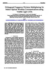
where dT = [d0 d1 · · · dM −1 ] corresponds to the symbols being transmitted in a frame and Z represents the basis functions. Using the orthogonality of the Z matrix, and compensating for the effects of the transmission channel we are able to find estimates of the symbols [9]. Suppose that we wish to sent M symbols for each user u such that each of these users have their own chirp carrier, then we will have a chirp basis � � 2 T ej(uωm t+πt θ/T ) (8) zum (t) = s t − u 2M for u = 0, · · · , U − 1. To pack the symbols in the most efficient way, we choose θ = 1/6 so that the instantaneous frequency of each of the chirps is IF (t) = uωm + πt/3T and a hexagonal TF lattice is obtained. The pulses dum zum (t) are obtained using the rotation property of the FrFT. This can be seen in Fig. 1, where we have divided the overall number of symbols into 4 groups and then converted each of these into a chirp with the hexagonal lattice structure as shown. The transmitting signal is thus y(t) =
M −1 U −1 X X
dum zum (t).
(9)
m=1 u=1
Given the narrow bandwidth of the PSWFs, the length of the transmitting signal is large so we need to decrease the sampling rate. In [10] we have shown that for a timelimited signal of length T and bandwidth B the minimum number of samples required by Nyquist (with sampling period Tn is Nn = T /Tn ≥ T B/π), i.e., it is connected with the time-bandwidth dimension of the signal. These samples will then be affected by the channel which changes the location of the chirps as they are delayed in time and shifted in frequency. The transmitter and receiver of the proposed TFDM system is shown in Fig. 2. For a time varying channel with L paths, each with attenuation factors {α` }, time delays {τ` } and Doppler frequency shifts {φ` } and noise η(t), the received signal would be
4. SIMULATIONS To illustrate the performance of the proposed TFDM, we performed Monte Carlo simulations and measured the bit error rate (BER) for signal to noise ratios (SNR) between −10 to 10 dB. For each SNR value 500 trials were performed. The effect of the channel is the addition of Gaussian noise. The results of our simulation are shown in Fig. 3. We considered U = 4 each with M = 64 bits. The results clearly display the robustness of the system to noise, in great part due to the time-frequency hexagonal lattice structure and the advantage of using chirp modulation by means of PSWFs. In the TF plane the added white noise is distributed all over, thus the advantage of using windowing and filtering. To show that the separation of the symbols and the pulses used to represent these symbols is important we ran a second simulation where we halved the separation between the original frequency spectra of the pulses and besides the PSWF pulses we used rectangular pulses. The rectangular pulse is similar to the chirp OFDM proposed by [7]. The BER increases for both rectangular and PSWF pulses compared with the previous simulation due to the decrement of the pulse separation. However, the BER results are better than those of the rectangular pulses due to the frequency concentration of the PSWF pulses.
25
20
20
15
15
10
frequency
= dT Z
as in the frequency or in the time domains. The channel noise will be distributed over the T-F plane and the T-F characterization of the chirps will not be affected by small time and Doppler delays. At the receiver we use the inverse FrFT to dechirp the received signal and then interpolate the resulting signal using a bank of windows and filters covering the time and frequency of the received signal. This allow us to recover a version of the sent signal, which when correlated with the different basis components we find estimates of the sent symbol.
frequency
yT = [y(0) · · · y(N − 1)] which can be expressed in matrix form as z0 (0) z0 (1) · · · z0 (N − 1) z1 (0) z1 (1) · · · z1 (N − 1) yT = dT ··· zM −1 (0) zM −1 (1) · · · zM −1 (N − 1)
10
5
0
0
−5
−5 −5
0
5
10
time
yr (nTs ) =
L X
α` y(nTs − τ `)ejφ` nTs + η(nTs )
5
15
20
−10 −5
0
5
10
15
20
25
time
(10)
`=1
for a channel where Ts is the PSWF sampling period. In the T-F plane the effects of the time and frequency shifts and the attenuation, as well as the effect of the noise are not as severe
Fig. 1. Generation of hexagonal lattice: (a) original PSWFs shifted in time and frequency, (b) chirp PSWF obtained from FrFT of original functions in (a).
1188
{zum (t)}
Rectangular PSWF
Slepian Sampling
FrFT
Channel
y(nTs )
yr (nTs )
BER
{dum }
0
10
TRANSMITTER −1
10
yr (nTs )
Channel Equalizer
Windowing Filtering
IFrFT
Correlator Detector
−10
−4
−2
0
2
4
6
8
10
Fig. 4. BER vs SNR of second Monte Carlo simulation of TFDM using rectangular and PSWF transmission pulses separated P = 256 samples, and M = 64 bits.
Fig. 2. Transmitter (top) and receiver diagram for the proposed TFDM system.
6. REFERENCES [1] W. Kozek and A. Molisch, “Nonorthogonal pulseshapes for multicarrier communications in doubly dispersive channels,” IEEE Journal on Selected Areas in Communications, Vol. 16, pp.1579–1589, Oct. 1998.
5. CONCLUSIONS In this paper we have presented a novel time-frequency division multiplexing system that uses both time and frequency division. The advantage of our method over conventional OFDM are: (1) the chosen PSWF provide time-limited pulses with optimal energy concentration; (2) the chirp modulation is more appropriate for typically time-varying channels; and (3) the robustness to noise inherent in the hexagonal timefrequency lattice structure. Our method replaces the conventional FFT with the FrFT, the conventional Fourier basis with chirp basis.
[2] S. Barbarossa and A. Swami, “Estimation of time-varying multipath channel parameters using chirp signals,” ISIT2001, Washington, DC, Jun. 2001. [3] A. Vahlin and N. Holte, ”Optimal Finite Duration Pulses for OFDM,” IEEE Trans. Comm., vol. 44, pp. 10–14, Jan. 1996. [4] D. Slepian, “Prolate spheroidal wave functions, Fourier analysis and uncertainty. V: The discrete case, ” Bell Syst. Tech. J., Vol. 57, pp. 1371–1430, 1978. [5] L. B. Almeida, “The fractional Fourier transform and timefrequency representations,” IEEE Trans. Signal Process., Vol. 42, pp. 3084–3091, Nov. 1994.
0
10
[6] H. M. Ozaktas, Z. Zalevsky, M. A. Kutay, The Fractional Fourier Transform with Applications in Optics and Signal Processing. John Wiley, New York, 2001.
−1
10
BER
−6
SNR (dB)
RECEIVER
[7] M. Martone, “A Multicarrier system based on the Fractional Fourier Transform for time-frequency selective channels,” IEEE Trans. on Communications, Vol. 49, no. 6, pp. 10111020, Jun. 2001.
−2
10
[8] T. Strohmer and S. Beaver, “Optimum OFDM design for timefrequency dispersive channels,” IEEE Trans. on Communications, Vol. 51, pp. 1111–1122, Jul. 2003.
−3
10
[9] S. Senay, L. F. Chaparro, A. Akan,“Chirp channel estimation and OFDM transmission using discrete prolate spheroidal sequences,” SPPRA, Vol.64, pp. 281–286, Feb. 2008, Innsbruck, Austria.
−4
10 −10
−8
{d˜um }
−8
−6
−4
−2
0
2
4
6
8
10
SNR
Fig. 3. BER vs SNR of first Monte Carlo simulation of TFDM using PSWF transmission pulses separated P = 512 samples, and M = 64 bits .
[10] S. Senay, L. F. Chaparro, and L. Durak, “Reconstruction of nonuniformly sampled time-limited signals using Prolate Spheroidal Wave Functions.” In press, Signal Processing.
1189