International Journal of Computer and Communication Engineering, Vol. 2, No. 5, September 2013
A Time Synchronized Wireless Sensor Tree Network using SimpliciTI Vaibhav Pratap Singh, Nitin Chandrachoodan, and Anil Prabhakar
transceiver are ON. It can also perform RE or ED functionality.
Abstract—SimpliciTITM is a low power radio frequency protocol from Texas Instruments (TI), which supports peer to peer and star topologies. The system uses Access point (AP) as data hubs, and end devices (ED) to realize the sensor functionality. APs need to be always ON to ensure they can respond to join requests from new EDs and collect data from existing EDs in the network. This is not practical with long-running battery operated APs. We can reduce the energy requirements in the network by putting APs to sleep, but this requires careful synchronization so that the APs will be ready to receive data when the EDs transmit. We implement a time synchronization algorithm to ensure that APs are awake whenever an ED sends data. We also propose a simpliciTI based tree topology where one ED (named PCED, personal computer end device) is made common to the network of multiple APs and now PCED acts as the data hub. To manage the data traffic at the PCED we implement time division multiplexing along with store and forward function on EDs and APs.
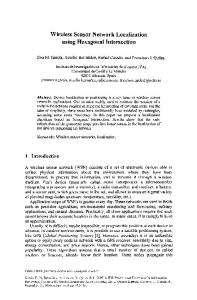
Fig. 1. SimplicTI Architecture [1].
D. SimpliciTI Architecture It has three layers as shown in Fig. 1, the minimal RF interface layer (MRFI), the network layer and the application layer. The transceiver frames the data and thus functions as the physical and data link layer. SimpliciTI has a set of application programmable interfaces (APIs) at the application layer which allow the user to setup bidirectional links, send messages from one device to another etc [4]. The application layer is blind to the transceiver and network configurations. All this makes it very easy for the user to setup a network and modify its operation according to the application. The supported frequencies are 480, 868, 915, 955 MHz and 2.4 GHz [2]. The protocol runs on Texas Instruments’ ultra-low power microcontrollers (µC) and transceivers. One such device is the eZ430-RF2500. It is shown in Fig. 2. It has a MSP430F2274 µC interfaced to the CC2500, RF transceiver (TxRx, 2.4 GHz), through a serial peripheral interface (SPI) [3]. Both the µC and transceiver have sleep modes which reduce power consumption. TI describes a “wireless sensor monitor” application using the eZ430-RF2500 [1]. The application uses the SimpliciTI based star topology to setup the network as shown in Fig. 3. In the application the EDs act as the sensor terminals (field devices) and send the battery voltages and temperature readings to the AP and go to sleep. AP sends this data to the PC com port over universal asynchronous receiver transmitter (UART) which can be seen on the provided graphical user interface (GUI) or on hyper terminal in Windows [3]. We can easily modify this application to sense other environmental parameters as well. The AP should remain always ON to ensure that new EDs can join the network at any time and existing EDs can send data at any time. AP's power consumption is not an issue as long as it is connected to the PC. However if we take the AP also to the field and operate it on
Index Terms—Star and tree topology, time division multiplexing in wireless sensor networks, time synchronization in SimplicTI, wireless sensor networks.
I. INTRODUCTION SimpliciTI, a radio frequency (RF) protocol by TI, is used to setup wireless sensor networks [1]. It is suitable for battery operated devices working at low data rates of up to 250 kbps [2]. It supports peer to peer and star topologies [2]. The basic device types available in the protocol are access point (AP), range extender (RE) & end device (ED) [2]. A. End Device ED implements the sensor functionality. It may or may not be always ON. It can be a transmit only device or a transmit-receive device. B. Range Extender A typical line of sight range of a link between two devices is about 50 m [3]. Using a RE allows up to 100 m. A maximum of four hops are allowed [2]. It is an always ON device. It retransmits each unique frame it receives. It can also perform ED functionality. C. Access Point AP does tasks like network management, store and forward if a receiver (Rx) device is asleep, retransmission of data etc. Only one AP is allowed per network [2]. It is also an always ON device. By ON we mean that both microcontroller and Manuscript received March 27, 2013, revised May 8, 2013. The authors are with the Department of Electrical Engineering at Indian Institute of Technology Madras, Chennai, India (e-mail:
[email protected]).
DOI: 10.7763/IJCCE.2013.V2.251
571
International Journal of Computer and Communication Engineering, Vol. 2, No. 5, September 2013
We use the “time-sync protocol for sensor network” (TPSN) [6] to implement time synchronization. In a star network an ED sends a data packet to its AP with its time stamp (T1) on it. The AP on receiving the data packet adds its time stamp (T2) on it. The AP sends the data packet back to the ED after adding the send time stamp (T3) in it. ED on receiving adds the last time stamp (T4) and then calculates the drift. This drift is given by
batteries its power consumption becomes an issue as AP should always be kept ON.
Fig. 2. The hardware layout of an eZ430-RF2500 device [3].
One method to address the above issue is to predetermine the network size along with the data transmission time and put AP also to sleep between measurement cycles. However, to ensure that the AP is awake when the EDs send the data we implement time synchronization in the network. In this paper, we describe the methodology to implement time synchronization in the SimpliciTI based star topology and talk about the improvement in the energy consumption after the implementation. We also extend SimpliciTI to design a tree topology utilizing the principles of time division multiplexing along with store and forward functionality.
II. METHODOLOGY As mentioned earlier the AP is always ON in the star network and is powered by the PC. If we take APs also to field, like EDs, and power them using batteries the power consumption will be high. One way is to fix the time for new EDs to join the network and for data transmission to the AP from the existing EDs. Now we can put AP also to sleep and implement time synchronization every hour to ensure that the AP is awake when the EDs send the data or join request. We run a real time software clock on both AP and EDs [5]. One of the 16 bits timer modules on the µC is used to trigger this real time clock. We use an external 8 MHz quartz crystal to get a stable and accurate clock signal. The internal divide by 8 circuits is used to get a 1 MHz clock for the timer module. This gives us a minimum granularity of 1 µs. The quartz crystal is connected to XIN and XOUT pins of the µC. However these pins were used to generate interrupt on the µC whenever a data is received by the TxRx (GDO0 and GDO2 pins). These GDO0 and GDO2 pins of the TxRx are now connected to pin 0 and pin 1 of port 2 on the µC. The simpliciTI protocol stack is accordingly modified.
1 [(T 2 T1) (T 4 T 3)] 2
(1)
This drift is then added to the ED time as shown in Fig. 4. As the clocks of devices in the network are synchronized we put the AP to sleep and turn it ON whenever we expect data from EDs. Even in the ON state the µC on the AP is put to sleep as soon as it finishes its work while the TxRx remains ON as long as we expect data. The TxRx on receiving the data generates an interrupt on the µC which in turn wakes up, processes the data and again goes to sleep. The TxRx ON duration is determined by the time synchronization accuracy. The worst case synchronization error of TPSN is about 45.2 µs at 4 MHz clock [6]. But a typical quartz crystal sourced clock varies by 40 ppm [7]. Thus two quartz crystal sourced clocks can drift by 40 µs in 1 s i.e. about 150 ms per hour. As we do time synchronization every hour the duration accounting for the synchronization error should be 150 ms + 150 ms (guard time) = 300 ms approximately. There will be two additional transmission and two reception events to implement time synchronization once every hour between a pair of one ED and the AP. With 8 EDs in the star network there will be 8 such pairs and hence there will be additional 16 transmission and 16 reception events per hour. We did an approximate theoretical analysis of the overhead at AP due to implementation of time synchronization. The analysis is for a measurement cycle of one hour which consists of only time synchronization events. It is given in Table I. Each ED is given a window of 5 ms to synchronize itself to AP. Thus AP’s TxRx is ON only for a window of about 340 ms every hour accounting for the duration due to time synchronization error (300 ms) and its implementation ( 8 × 5 ms = 40 ms). The AP has to do 16 transmission events thus will operate in Tx mode for 800 µs × 16 = 12.8 ms as shown in Table I. It will operate in Rx mode for the rest 340 - 12.8 = 327.2 ms.
Fig. 4. Timing sync protocol for sensor networks [6].
If we consider the energy consumption of a “eZ430-RF2500” hardware module during ON duration, the µC draws a current of 2.7 mA at 8 MHz, 3 V (in active mode)
Fig. 3. SimpliciTI based Star topology for “wireless sensor monitor” application.
572
International Journal of Computer and Communication Engineering, Vol. 2, No. 5, September 2013
and the transceiver draws 18.8 mA (in Rx mode) at 3 V as shown by bold letter in Table I [1]. When both the µC and TxRx on the AP are always ON the hardware consumes ≈ 77.4 A•s {(2.7 + 18.8) mA ×3600 s} approximately (other contributions are negligibly small). When we put the µC to sleep keeping only the TxRx always ON, the energy consumption goes down to ≈ 67.68 A•s (18.8 mA × 3600 s) approximately. However after the implementation of time synchronization the energy consumption falls to ≈ 11.34 mA•s approximately as shown by bold italics in Table I. This ensures a longer battery life. Thus time synchronization enables the user to put the AP to sleep which brings down the power consumption effectively.
Fig. 5. SimpliciTI based tree topology for “wireless sensor monitor” application.
TABLE I: ENERGY CONSUMPTION OVERHEAD DUE TO TIME SYNCHRONIZATION IMPLEMENTATION IN A CYCLE OF 1 HOUR AT AP [1]. Radio Events XOSC startup Ripple counter timeout Idle mode PLL calibration
Current Consumed 2.7 mA
Time Executed 300 µs
Energy Consumed 810 nA•s
1.75 mA
150 µs
262 nA•s
1.5 mA 7.5 mA
375 µs 809 µs 800 µs x 16 = 12.8 ms 327.2 ms 3599.66 s Total Time Executed 2.705 ms x 32 = 86.56 ms
563 nA•s 6,067 nA•s
TX mode
21.2 mA
RX mode Radio sleep
18.8 mA 400 nA
MSP Events
Current Consumed
MSP430 active current MSP430 Low power mode 3
2.7 mA 900 nA
0.271 mA•s ≈6.15 mA•s ≈1.44 mA•s ≈7.87 mA•s
Energy consumed 0.234 mA•s
3599.91 s
3.24 mA•s
Total Transmission total
3.47 mA•s
the address space is 4 bytes and thus the theoretical limit for number of devices connected to the PCED and an AP is 232. However due to the RAM size limitation on the hardware this number is limited to 30 devices [1]. We use a maximum of 8 connections to the PCED and an AP to keep more memory for further application development. The same approach is used in [1]. The PCED can connect to a maximum of 8 sub networks. Thus the tree network can have a maximum of 64 + 1 (PCED) devices. The same methodology shall work fine if we allow more connections to the PCED and the APs, as it involves two hops of data from ED to PCED the line of sight coverage distance of the network will be 100 m from the PCED.
B. Data Traffic and Time Division Multiplexing As the number of devices in the network increases the data traffic at the PCED will also increase. This may result in a loss of data. We can avoid this possible loss if we time multiplex the data from the sub star networks and then send it to the PCED. As shown in Fig. 8 devices in tree topology function in a defined order. We first turn ON all the APs, followed by PCED. Then we turn ON the EDs to setup the sub star networks. Once all the sub networks are formed we get a full tree network.
11.34 mA•s
A. SimpliciTI based Tree Topology The implementation of time synchronization enables us to operate AP on batteries effectively. Utilizing this feature we form a SimpliciTI based tree topology as shown in Fig. 5. The flow charts in Fig. 6 and Fig. 7 describe the working of an ED and an AP in a star network. An ED on being turned ON broadcasts a default join token already known to the AP. The AP on receiving this join token (assuming AP is already ON) sends an acknowledgement back to the ED as link token. The ED responds by sending this link token back to the AP and in turn the AP registers it as one of the nodes in the star network and sends a link reply [1, 8]. Join and link tokens ensure that a ED doesn’t join multiple networks. We use different join and link tokens to form multiple sub star networks each with a maximum of 7 EDs. Now consider a new device type named as the personal computer end device (PCED). PCED on being turned on broadcasts respective join tokens and establishes a link to all the sub networks one by one. This enables the PCED to connect to multiple APs and form the tree network. The PCED assigns a separate port to each AP and stores the AP’s address as well. Features of the tree network are the PCED is the data collecting node, there won’t be cross talk amongst sub star networks due to the use of different join and link tokens,
Fig. 6. ED’s flow chart for star topology [1], [8].
573
International Journal of Computer and Communication Engineering, Vol. 2, No. 5, September 2013
III. RESULTS For testing we form a network using tree topology consisting of two sub star networks with two EDs in each. The collected data is shown in Table II. It shows data for the first measurement cycle. The data in bold letters is sent by one sub star network to PCED at 0:0:0.403 (h:m:s.ms) and the data in italics is sent by another sub star network to PCED at 0:0:0.431 (h:m:s.ms). TABLE II: DATA RECEIVED IN THE FIRST MEASUREMENT CYCLE Address AP
Fig. 7. AP’s flow chart for star topology [1], [8].
We implement the “wireless sensor monitor” application using tree topology where the EDs send the battery voltages and temperature readings to the APs every hour. First 300 ms are left to account for any time synchronization error. Next 40 ms are for each AP to synchronize itself with respect to the PCED one by one. Each AP is given a window of 5 ms to synchronize. In the next 35 ms each ED in a sub star network implement time synchronization one by one. EDs store the time synchronization data at this point. All EDs measure battery voltage and temperature just after getting time synchronized to APs. They store these readings as well. In the next 28 ms, with 4 ms given to each ED, all the EDs in a sub star network transmit both the time synchronization data and measurement data. Now AP stores data from all 7 EDs. In the last 224 ms each AP sends all the stored data to the PCED one by one. Each AP is given a window of 28 ms to transmit all the stored data. EDs sleep as soon as they finish their work. APs remains ON for a window of 627 ms (worst case) each hour. Thus store and forward function at APs and EDs along with time division multiplexing of data enables the network to self-manage the data traffic [9]. Also the store and forward with time division multiplexing takes place at the application layer and thus the user can modify them according to the application at hand.
1 1 2 2 1 1 1 1 2 2 2 2
ED
1 2 1 2 1 2 1 2
Time (h:m:s.ms) PCED
AP
0:0:0.300 0:0:0.304 0:0:0.305 0:0:0.309
0:0:0.266 0:0:0.304 0:0:0.294 0:0:0.308 0:0:0.344 0:0:0.349
0:0:0.344 0:0:0.349
Data ED (Sync.)
Voltage (V)
Temp. (oC)
2.6 2.9
34.5 35.6
2.8 2.7
35.3 34.1
0:0:0.344 0:0:0.349
0:0:0.343 0:0:0.349
IV. CONCLUSION We successfully implement time synchronization in SimpliciTI based star topology enabling us to put APs also to sleep and hence reduce the effective energy consumption of the network. We also design a SimpliciTI based tree topology which has features like a new device type PCED is introduced in the network. a maximum of 64 + 1 (PCED) devices can be connected in the network. Even more devices can be connected if we allow more connections to APs and PCED. a store and forward functionality at the AP and ED along with time division multiplexing reduces the data traffic at the PCED. line of sight coverage distance of 100 m from the PCED. can be used in applications like structural monitoring, agricultural monitoring etc [10]. ACKNOWLEDGMENT The authors are thankful to Texas Instruments for providing the “eZ430-RF2500” wireless development tool along with all the essential software and documents. REFERENCES [1] [2] [3] [4]
Fig. 8. Store and forward function with time division multiplexing of data.
574
Wireless Sensor Monitor Using the ez430-RF2500, Application report, Texas Instruments, Dallas, Texas, April, 2011. SimpliciTI: Simple Modular RF Network Specification, Specification sheet, Texas Instruments, Dallas, Texas, March 24, 2009. eZ430-RF2500 Development Tool, User's guide, Texas Instruments, Dallas, Texas, April 2009. SimpliciTI Application Programmable Interface User's guide, Texas Instruments, Dallas, Texas, March 24, 2009.
International Journal of Computer and Communication Engineering, Vol. 2, No. 5, September 2013 [5]
Using the Real-Time Clock Library, Application report, Texas Instruments, Dallas, Texas, January 2011. [6] S. Ganeriwal, R. Kumar, and M. B. Srivastava, “Timing-Sync Protocol for Sensor Networks,” in Proc. the First International Conference On Embedded Networked Sensor Systems (SenSys 2003), pp. 138-149, November 2003. [7] Y.-C. Wu, Q. Chaudhari, and E. Serpedin, “Clock Synchronization in Wireless Sensor Networks,” IEEE Signal Processing Magazine, vol. 28, pp. 124-138, January 2011. [8] SimpliciTI: Simple Modular RF Network, Developers Notes, Texas Instruments, Dallas, Texas, October 27, 2009. [9] A. A.-E. Humos, M. Cardei, B. Alhalabi, and S. Hsu, “Medium Access Control Protocols for Wireless Sensor Networks,” in Wireless Sensor Networks and Applications, Yingshu Li, My T. Thai, Weili Wu, Ed. New York: Springer, 2008, ch. 4, pp. 87-112. [10] N. Xu, S. Rangwala, K. K. Chintalapudi, D. Ganesan, A. Broad, R. Govindan, and Deborah Estrin, “A Wireless Sensor Network For Structural Monitoring,” in Proc. the Second International Conference On Embedded Networked Sensor Systems (SenSys 2004), pp. 13-24, November 2004.
Nitin Chadrachoodan is currently a faculty member in the Department of Electrical Engineering, Indian Institute of Technology (IIT) Madras, Chennai, India. He obtained his undergraduate degree in Electronics and Communication Engineering from the same department in 1996, followed by a PhD from the University of Maryland at College Park in 2002. He primarily works in the areas of digital system design and VLSI / FPGA implementations of DSP systems. Anil Prabhakar is currently a faculty member in the Department of Electrical Engineering, Indian Institute of Technology (IIT) Madras, Chennai, India. He was previously with the Read-Rite Corporation, Fremont, CA, and at Bangpa-in, Thailand, working in various capacities in charge of the design, characterization, and production of magnetic recording heads for hard disk drives. He is also an active member of the Optical Components and Subsystems Group, Center for Intelligent Optical Networks, IIT Madras. His current interests include quantum electronics, nonlinear systems and alternative and augmentative communication devices.
Vaibhav Pratap Singh is currently pursuing a MS degree in the area of sensor networks at Indian Institute of Technology Madras, Chennai, India. He obtained his undergraduate degree in Electronics and Communication Engineering from Dehradun Institute of Technology, Dehradun in 2011. His research interests include embedded systems, optical communication and optical network design.
575