relationships the SM has in the model with other classes. The PSM ... The SR is an abstract class used only to show the relationships and aggregations on a.
A TINA based Prototype for a Multimedia Multiparty Mobility Service Javier Huélamo & Hans Vanderstraeten, Alcatel Telecom Juan C.Garcia, Telefónica I+D Juan C.Yelmo, Universidad Politécnica de Madrid George Pavlou, University College London
Abstract: The TINA architecture is emerging as an integrated approach to service and network control and management. The ACTS VITAL project aims to extend and refine the TINA architecture and validate it through the design, development and demonstration of a set of reusable components; the latter are used to realise services composed of multimedia, multiparty and mobility service features. This paper describes the results of the project’s first phase which resulted in field trials, focusing on the refinements and extensions with respect to TINA.
1. Introduction The Telecommunication Information Networking Architecture (TINA) is being defined by an international consortium (TINA-C) constituted by over 50 companies including the major network operators, computer suppliers and network equipment vendors. TINA is aimed to enable the efficient creation, deployment, operation and management of a wide range of services; taking full advantage of the most recent distributed processing and object orientation technologies; and paving the way for the emerging global multi-supplier multi-operator telecommunication sector. TINA-C was formed at the end of 1992. The period from 1993 to 1995 was devoted to the definition of this open distributed architecture. In 1996, a great effort have been invested to validate and consolidate TINA with the target of achieving a seamless and consistent reference architecture. VITAL (Validation of Integrated Telecommunication Architectures for the Long term) is both an ACTS project and a TINA auxiliary project whose main objective is to develop, demonstrate and validate a collection of reusable components based on TINA for developing, deploying, managing and using services composed of multimedia, multiparty and mobility service features. The project has adopted a phased approach where three European wide field trials will be carried out involving heterogeneous national host infrastructure. In each phase, a set of service features, stakeholders, subsystems, components, and transport infrastructure elements will be selected to validate several architectural aspects taking as main input the last version of the TINA deliverables available in the design stage. The validation results of each trial will provide feedback to TINA to refine and complete the architecture incorporating these improvements in new versions of the TINA deliverables which will be the base for the next trial. This phased approach not only allows a rapid first validation of the architecture, but will also evaluate its extendibility and reusability, both in terms of providing additional service features and using heterogeneous underlying transport technology. At the end of each phase feedback will be collected from all the relevant stakeholders.
This paper is based on the results [1] of the VITAL 1st trial (VITALv1) which has been finished at the end of October 1996. The following TINA business roles are supported: consumers, a retailer and a connectivity provider. This trial has been installed and demonstrated in the Spanish and Italian national hosts. After presenting the overall architecture defined for VITALv1, all the developed subsystems and their components are described in detail mentioning the main refinements and extensions with respect to TINA.
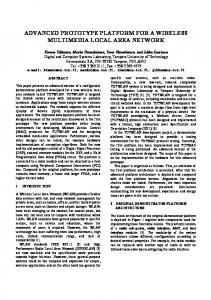
2. Overall Architecture for VITAL 1st Trial The TINA based architecture defined for the VITALv1 consists of components in the consumer or private domain, and in the provider or public environment which is composed of one retailer domain and one connectivity provider domain. In VITALv1, there are two types of terminals: end-user terminals and operator terminals. The enduser terminals in the consumer domain contain the end-user applications (EA) and a set of components which interact with other ones located in the retailer domain. Two end-user applications have been implemented in VITALv1: a session control application and a desk top videoconference application. These applications support the interaction with end-users; the interaction with subscribers will be incorporated in the 2nd trial (VITALv2). Therefore the subscription data is introduced by the retailer using an operator terminal. The operator terminals contain two types of applications: subscription management application (SA), which allows the interaction with the retailer, and resource configuration management application (CA) for the connectivity provider. Retailer Domain Subscription Application
Ret
Access Session Control Subsystem
Ret
Ret
Session Control Subsystem
Ret
ConS Connection Management Subsystem Resource Configuration Management Subsystem
DPE Domain
RCM Application Connectivity Provider Domain
Figure 1. Overall Architecture for VITAL 1st Trial.
End User Application
End User Terminal Subsystem
Consumer Domain
Subscription Management Subsystem
End User Terminal Subsystem
End User Application
Consumer Domain
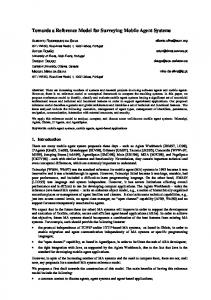
The architectural components developed are distributed units or computational objects (COs). These components are over a Distributed Processing Environment (DPE) installed in the terminals and in computing nodes within the retailer and connectivity provider domains. The DPE selected for VITALv1 is the IONA’s Orbix 2.0. which is CORBA compliant. All the terminals in VITALv1 will be based on workstations with DPE. The DPE kernels are interconnected by means of a kernel transport network over TCP/IP. The transport network used is an ATM network provided by the Spanish National Host (NH) and the Italian NH. The components of VITALv1 are grouped in the following subsystems: End-User Terminal Subsystem (EU), Access Session Control Subsystem (AS), Session Control Subsystem (SC), Subscription Management Subsystem (SM), Connection Management Subsystem (CM), and Resource Configuration Management Subsystem (RC). The Figure 1 depicts the developed applications and subsystems within the corresponding domains. Currently two TINA reference points (RP) are partially supported: the Ret-RP between the consumer domain and the retailer domain, and the ConS-RP between the retailer domain and the connectivity provider domain. New components as the Provider Agent will be incorporated in the next trials to align the architecture with TINA deliverables’96. The Figure 2 presents the main COs and their interfaces in the consumer and retailer domains. The EU subsystem of the consumer domain contains the following COs: User Application (UAP), Generic Session End Point (GSEP) and some COs associated with the connection management in the terminal. Retailer Domain
Subscription Application
STH
SubM
SubRg
SubAg
SubAg Subscription Manag.
UCxt Computational Object not supported in the 1st Trial
UCxt
UA
UA
Consumer Domain
Consumer Domain Session Control
End-User Application
Access Session Control
SF SSM
UAP
USS
GSS
USS
UAP
GSEP
USC
GSC
USC
GSEP
Terminal CM Connectivity Provider Domain
USM
End-User Application
USM
Connection Management
Figure 2. Main COs in Consumer and Retailer Domains
Terminal CM
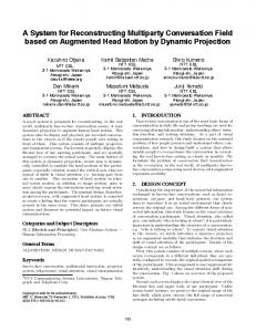
The retailer domain consists of the three subsystems: the SM subsystem which interacts with the SA application, the AS subsystem which interacts with the EU subsystem in the consumer domain, and the SC subsystem which interacts with the CM subsystem in the connectivity provider domains. The SM subsystem is composed of the following COs: one Subscription Agent (SubAg) per User Agent, Service Template Handler (STH), Subscriber Manager (SubM) and Subscription Register (SubRg). The AS subsystem is formed by the following COs: one User Agent (UA) and one User Context (UCxt) per end-user. The UA interacts with the Service Factory to create instances of user sessions and service sessions. The SC subsystem consists of the CO Service Factory (SF) and two types of building blocks: User Session Manager (USM) and Service Session Manager (SSM). These building blocks contain service specific COs and service independent COs. The User Service Segment (USS) belonging to the USM and the Global Service Segment (GSS) belonging to the SSM are service specific COs, these components have not been developed in VITALv1. The User Service session Control (USC) belonging to the USM and the Global Service session Control (GSC) belonging to the SSM are service independent COs. The UAP will interact via the GSEP with the USC and GSC in VITALv1. The main COs and their interfaces in the connectivity provider domain are shown in Figure 3. This figure also presents the main information objects handled in each interface of the CM subsystem. This domain is formed by the CM subsystem and the RC subsystem. GSC
Session Control Logical Connection Graph
RCM Application
CSM
Nodal Connection Graph Physical Connection Graph
MRCM
UAP Terminal Connection Management
CC End-User Terminals
Trail
LNC
Tandem Connection Subsnetwork Connection
CMC
NML-CP Subsnetwork Connection
NRM EML-CP Resource Configuration Management
VC/VP Connection
RA
Connection Management
Connectivity Provider Domain
Figure 3. Main COs in Connectivity Provider Domain
Computational Object not supported in the 1st Trial
The CM subsystem contains the following COs: Communication Session Management (CSM) which converts logical connection graph requests to physical connection graph requests and it will not be developed in VITALv1; Connection Coordinator (CC) which converts physical connection graph requests to trail requests in the corresponding layer network and it will interact directly with the GSC in VITALv1; Layer Network Coordinator (LNC) which converts trail requests in subnetwork connection requests; Network Management Layer-Connection Performer (NML-CP) which converts subnetwork connection requests in children subnetwork connection requests, LNC could request tandem connections to other LNC via its federation interfaces although this feature will not be supported in VITALv1; Element Management Layer-Connection Performer (EML-CP) which converts subnetwork connection requests in VC/VP connections in the corresponding network element via its associated Resource Adaptor (RA). The RM subsystem is composed of the following COs: Management Resource Configuration Manager (MRCM), Connection Management Configurator (CMC) and Network Resource Map (NRM). The RCM Application interacts with the MRCM to configure the network resources in the NRM and to launch one CMC per layer network. The CMC is in charge of launching the corresponding LNC and CPs via their configuration interfaces. The MRCM also launches the CC (if it has not yet been launched) and tells it the references of all the LNCs.
Fac
UAP Access Client
a
UAP Session Client s1 s2 s3
s2
s3
a GSEP s1 s2
s3
Fac
Conf Fac x-DCO
Fac
TINA Login
Fac
End User Application
UAP s1
T_CC tcg1
tcg2
Port1 Port2
End User System Subsystem
Conf Fac z-DCO
Port1 Port2
Figure 4. EU Computational Model
3. End User Terminal Subsystem This subsystem consists of the components in the consumer domain. The computational model of this subsystem is shown in Figure 4. This figure depicts the situation where the terminal is involved in 3 active service sessions (s1, s2 and s3). UAP and GSEP have been taken over from [2]. However, while TINA models UAP as a completely integrated application, VITALv1 models UAP to provide a more high-level API on top of which actual applications can be more easily developed. The TINA Login component allows users to login/logout as TINA users. This component is application-independent and creates the UAP Access interface passing the received authentication data which are checked within the retailer domain and if successful, the request and indication interfaces of the UAP Access Client are created. The UAP Access Client component is also application-independent. It implements the abilities to use TINA access facilities (e.g. request a new session, request to join an existing session, receive an invitation to join a session). The UAP Access Client provides the interfaces: Request interface towards the UAP Session Client, Indication interface towards the UAP, and Factory interface towards the TINA Login component to allow creation of Request and Indication interfaces. The UAP Session Client component implements the abilities to use the Session Control capabilities of the UAP. This component is application-specific. It can decide which session control changes can be initialized by the user, respond to indications on session control changes, and decide which of the information on session control change will be presented to the user. Furthermore, this component can also request for a new session (via the UAP Access Client request interface) and respond to incoming invitations to join a session. The component provides the Session Control interface (s*) towards the UAP; and Factory interface towards the UAP Access Client to allow creation of Session Control interfaces. The UAP provides a higher layer API to enable a faster application development. It can also be considered as a gateway to non-CORBA applications. Its “server interfaces” could be developed using e.g. UNIX sockets, enabling an access to applications which are not implemented as CORBA objects. The UAP provides the Access interface (a) towards the UAP Access Client and GSEP; Session Control interface (s*) towards the UAP Session Client and GSEP; and Factory interface is used by the TINA Login to allow creation of the UAP Access interface. The GSEP is the single point of contact in the consumer domain for both the access and service session. It offers an Access interface towards the UAP and UA; and a Service Control interface towards the UAP and USC, different Session Control interfaces are created for different sessions. It has been developed in accordance with [2]. This means that it also acts as the contact point for the access session, while in [3] the Provider Agent has been introduced. VITALv1 introduces the Terminal Connection Coordinator (T_CC) and the Device Controller Objects (DCO) to manage connectivity within the consumer domain. The T_CC coordinates the technology layers in the terminal, similar to the CC in the
network. It should negotiate with the peer T_CC and the CC about the selection of the technology layers. In VITALv1, this selection is pre-programmed. The T-CC provides Terminal Connection Graph interfaces towards the GSEP and a Factory interface to create TCG interfaces. A port within a TCG represents the termination of a user information stream within the consumer domain. Such a termination is typically implemented as a protocol stack. Every protocol stack element represents a technology layer modeled as a separate DCO (e.g. MJPEG DCO, AAL5 DCO). A DCO provides Port interfaces to handle a specific protocol layer; a configuration interface to configure the corresponding protocol layer; and a Factory interface to create Port interfaces.
4. Subscription Management Subsystem This subsystem (see Figure 2) provides to the retailer, via the corresponding subscription application, functions to subscribe/cancel subscribers, to collect/modify/show subscription information, to authorize/bar service use for Subscription Assignment Groups (SAGs) associated with subscribers, and to determine the subscription information available to a user during service access. The SM information model considers the following information objects: Service Description, Service Template, Subscription, SAG, Service Profile, Subscription Contract, and Subscription Portfolio. The SubRgs allows to collect/modify/show/cancel subscription information. A single SubRgs handles the subscriptions of one service. The SubRgs maintains the subscription contract, subscription and service profile information objects. The SubAg allows its clients (UA) to get subscription information about a particular user during an access session. In particular, the SubAg provides a list of services available and a description of a service to be executed for a user. Subscription operators interact with SubAg through the SA application to assign/deassign Service Profiles to SAGs. The SugAg is created by the corresponding UA. There is a SubAg per UA. The STH handles one or more service templates that represents service capabilities provided by the service retailer, and verifies subscription characteristics on request of the corresponding SubRgs. The SubM manages the information of subscribers, subscription portfolios and SAGs. The SubM CO is independent of any particular service. The SM subsystem is based on [2] [4] although some extensions and refinements have been done in order to make them suitable to VITALv1 requirements. The most relevant are: common definitions have been updated and extended; GSEP can interact directly with SubRg to get subscription data on behalf of the end-user; and COs that create dynamically other COs export their references to the trader.
5. Access Session Control Subsystem This subsystem allows the access to the services offered by the retailer providing a limited personal mobility functionality where the user can register on any terminal to receive invitation of a particular service and can request to establish a service sessions from any terminal. Some authentication mechanisms are also available. This subsystem is composed of two type of COs: UA and UCxt (see Figure 2). The UA represents a user in the retailer domain. The UA is the single point of contact to access the available services within a retailer domain. The UA provides some capabilities to handle sessions allowing a user: to create a new session, to join in an existing session, to be invites to participate in an existing session, to leave from an existing session, to delete an existing session. The UA also provides the list of services available in a retailer domain via the SubAg and the list of existing and public sessions via the SF. The UA allows to authenticate the user. Personal mobility is also provided being able to register on a terminal for incoming communication. The registration information is handled in the corresponding UCxt. There is one UA per user in the retailer domain and each UA has associated one UCxt. The UAs are created by the SubM when a new user is defined in the SA Application. When a UA is created, the corresponding UCxt and the SubAg are created by this UA. The UAs interact with the SF to create or delete service sessions and user sessions handled in the GSC and USC respectively. The GSEP and the GSC are the clients of the UA interfaces. The UA interact with a Authentication Server, USCs, GSEPs and SubAgs. The UAs are the clients of the UCxt interfaces. The AS subsystem is based on [2] [4] although some modifications have been introduced. The main changes in the IDL definitions of the information objects are: the session Id has been included in the session description, the reference included in the service execution information is a USC reference, and several new information objects have been introduced (terminal configuration, user configuration and terminal registration). In the computational model, the main changes have been: the Personal Profile has not been developed; the Terminal Equipment Agent has been replaced by information objects; and the Provider Agent and Initial Agent proposed in [3] has not yet been considered.
Service Session
Session Graph
Session Member (SM)
Party
Session Relationship (SR)
Control SR
Resource
Access SR
Ownership SR
Write Stream Interface
Source Port
Sink Port
Read
Port
Source-SinkPort
Connectivity SR
Pt-Pt-Uni
Pt-Pt-Bi
Pt-MtPt
Mpt-Pt
Mpt-Mpt
Figure 5. Service Session Graph Overview
6. Session Control Subsystem This subsystem is in charge of handling the user and service sessions associated with the services available in the retailer domain. In VITALv1, there is only one service provided by the retailer. This service offers the operations to manage the Session Graph (SG) concept. This functionality is performed by service independent components according to TINA specification. An overview of the TINA Service Session model is represented in Figure 5. The elements in gray will not be implemented in VITALv1. The Service Session (SS) contains one -and only one- SG object. A SS is composed of Session Member (SM) and Session Relationship (SR). The SM is an abstract class used only to show the relationships and aggregations on a generalized level in the model. The SM is further specialized as Party Session Member (PSM). All the SM properties are inherited by PSM, including all the relationships the SM has in the model with other classes. The PSM represents a negotiating entity taking part in the session. The user takes part in the session by defining itself as a PSM in the SG. A user invites another one in the session by requesting such a PSM to be created for that invited user. The SM is also defined as an aggregation of Stream Interfaces (SI). The SI represents a grouping of related Port objects. A Port represents a source, sink or source+sink of a stream of user information. A Port is composed of the attributes: information type, direction, port description and port address. The SR is an abstract class used only to show the relationships and aggregations on a generalized level in the model. The SR is further specialized as Control SR and Connectivity SR. All the SR properties are inherited by Control SR and Connectivity SR, including all the relationships the SR has in the model with other classes. The
Connectivity SR models, from the Service Session point of view, a stream binding (expressing the request for user information exchange). The Connectivity SR contains the following attributes: information type, topology and connection description. The Control SR is also specialized into the Ownership SR (OSR). The OSR associates a PSM to any other SG object instance in the session graph. In VITALv1, this subsystem is composed of the following COs: SF, USC and GSC (see Figure 2). The USC and GSC implement the service common parts of session control. The service specific parts are not implemented in VITALv1. The SF’s usage interface is invoked by UAs. The USC provides interfaces towards the SF, GSEP and GSC. The GSC provides interfaces towards the SF and USC. The USC and GSC session control interfaces represent operations on the Session Control information model defined by the SG. The SC subsystem is partially based on [3]. TINA allows more than one SG object in one Service Session. This is not supported in VITALv1. The following SG elements are not supported in VITALv1: resource session member, write and read access control relationships, mpt-pt and mpt-mpt connectivity relationships, and SM and SR groups. The SG objects do not implement a scheduling mechanism. The following restrictions apply to the OSR: the owner in the OSR can only be a PSM, not a PSM Group; the ownership type is always equal to the semantics of “owned-shared” as specified by TINA; and the only voting rule supported by the ownership relation is 100% unanimity. The Port and Connectivity SR classes are not further specialized, but an attribute is introduced to distinguish between the conceptual sub-classes.
7. Connection Management Subsystem This subsystem provides connectivity capabilities to the retailer domains. The CM information model is based on the TINA Network Resource Information Model (NRIM) [5] which started by considering the object classes identified in ITU-M3100 and some extensions have been introduced. The NRIM is decomposed in several fragments.
Session Member
SML
PCG
PCGFactory
CC::Config
CC
MRCM
CC LNCFactory
Trail
LNC ATM_VC SNCFactory
SNCFactory
EML
CMC
SNC
NML-CP 1
NML
LNC::Config
SNC
EML-CP 1.1
CP::CpMgmt
SNCFactory
EML-CP 1.2
RA
RA
RECIBA
RECIBA
CP::CpEmlMgmt
NEL SNW1.1
SNW1.2 SNW1
Figure 6. CM Computational Model
For CM computational model, TINA defines two types of COs: those which are concerned with offering an interface to service components independent of network structure and technology (CSM and CC) and those which are concerned with the connection management within a layer network (LNC and CP). The VITALv1 CM computational model is depicted in Figure 6. For a layer network partitioned in several connection management domains, there is a LNC, for each of these domains, which serves the requests for trails to the clients of the layer network with access to the domain. The LNC relies on lower level entities, called CPs, which are able to provide subnetwork connections for the subnetwork in their scope. These entities are called NML-CPs. Each NML-CP relies on other NMLCPs, and finally on lower level entities, called EML-CPs which control directly network elements. The LNC and CPs are concerned with connections in a single layer network. They are specialized for the technology that is characteristic for that layer. When a trail spans different domains, a LNC interacts with other LNCs in the neighbor domains, using a federation mechanism, which is defined in terms of tandem connections (not supported in VITALv1). A Subnetwork Connection (SNC) corresponds to a CP interface. In other words, operations concerning creation, manipulation and interrogation of information represented by a SNC are defined on the CP. An operation on a CP is propagated along the CP hierarchy. Interworking of different layer networks is provided by the CC. The CC offers its clients one interface, defined in terms of a Physical Connection Graph (PCG), which allows to specify end-to-end connectivity between points which can be associated with different layer networks. This specification of the connection topology is independent of the technology and topology of the underlying networks. The CC will
take the client’s request, match the specified endpoints on compatibility, select the appropriate layer networks and requests the corresponding LNCs the further detailed connection set-up. A higher level of abstraction of the connectivity between service components is provided by the CSM. It provides for end-to-end connectivity among stream interfaces defined at the computational viewpoint. The CM subsystem is based on [5] [6] with the some modifications. In the following, there is a summary of the main changes. Only a part of the information model is used, attending to the VITALv1 requirements. A specialization of ports and lines has been included in the information model taking into account the allowed connection types (point-to-multipoint, point-to-point unidirectional and bidirectional). The connectivity services in VITALv1 are offered by CC, the CSM has not been developed. A new interface has been defined to configure the CC. It provides an operation to set the LNCs associated to the CC. A configuration interface for the LNC has been incorporated. It is used to set the top NML-CP supporting the Layer Network and to set the LN access points. EML-CP and NML-CP management interfaces have been refined and extended in order to allow for a more flexible configuration. The CM subsystem has the capability for selecting a termination point in case only the network address (or termination point pool) is specified by the user. In this case, it returns the identifier of the selected termination point. In VITALv1, the network address is an E-164 address and is associated to a pair . The termination point identifier indicates the particular VCI used in this pool. Groups of lines, trails or SNCs are not considered in VITALv1. A new interface, the Resource Adapter, has been defined in VITAL. This interface encapsulates the particular switch vendor implementation and associated switch control protocols. All the network elements will offer this common control interface independently of the particular implementation and protocols they offer. So in VITAL, the EML-CPs are technology dependent but vendor independent.
8. Resource Configuration Management Subsystem The Resource Configuration Management (RCM) [7] [8] [9] is responsible for managing the configuration of the components of the Resource layer. The resources can be network resources (e.g. LNW. SNW, trail), service resources (e.g. UA, TA, session), computing resources (e.g. node, capsule), and management resources (e.g. LNC, CP). The RCM is applicable not only to network resources, but also to other resource type. In [8], it is recognized the fact that within the Configuration Mgmt. domain, Network, Service and Computing Configuration Mgmt. exists, although the concept of Mgmt. Configuration Mgmt. is not explicitly mentioned. For example, the Connection Mgmt. Configurator (CMC) is in fact a Resource Configuration Manager for Connection Mgmt. resources (LNCs, CPs). In a similar way, although not yet
R C M clie n ts
defined by TINA, there could be a Fault Mgmt. Configurator or Performance Mgmt. Configurator. All of these Mgmt. Configurators belong to the RCM domain. The configuration mgmt. functional area can be applied to all types of resources in the TINA. This analysis leads to the conclusion that a new domain of Configuration Mgmt. is needed namely Mgmt. Configuration Mgmt. which contains one or several managers responsible for the “meta-management” of the TINA mgmt. architectural components. N e tw o rk A d m in istra tor (G U I)
C M , F M , e tc. C O s
q u e ries
R e so u rce C o n fig u ra tio n M a n a g e m en t
M an ag em e n t A d m in istra to r (G U I)
q u e rie s
q u e rie s
R e so u rce M a p
R e so u rce M a p
- P ro vis io n in g
- P ro vis io n in g
- S ta tu s a n d C o ntro l
- S ta tu s a n d C o ntro l
- In sta lla tio n S u p p o rt
- In sta lla tio n S u p p o rt
Inv e n to ry
Inv e n to ry
T o po lo g ica l vie w
M a n a g e m e n t R e so u rce C o n fig u ra tio n M an a g e r
M a n a g e d re so u rce s
N e tw o rk R e so u rce C o n fig u ra tio n M a n a g e r
T o po lo g ica l vie w
LNC
N M L-C P
N R C M o b ject gro up
no t in th e 1 st tria l
N M L -C P
E M L -C P E M L -C P
E M L -C P
clie n t/se rve r ro le C M o b je ct g ro up
Figure 7. Overall RCM Architecture for VITALv1
A result of this is that Connection Mgmt. Configuration is distinct from Network Resource Configuration Mgmt. They are both Resource Configuration Managers, but the former manages the configuration of Connection Mgmt. resources (CPs, LNCs) while the latter is responsible for the configuration of Network Resources (LNWs, SNWs, TPs, etc.). A benefit of this view is that it now becomes clear where to position CMC. Previously it has always been unclear whether CMC should be part of Connection Management or part of Resource Configuration Mgmt. The answer is that it is part of RCM but not part of Network Resource Configuration Mgmt. Figure 7 shows the initial proposal for the overall architecture of both NRCM and MRCM for VITALv1. The figure is informal and deliberately does not map directly to an information, computation or engineering model. The figure is divided into three layers. The center layer represents RCM, and contains both NRCM and MRCM which are not decomposed into their constituent COs. Although it is assumed that NRCM will be composed of several COs, only the Network Resource Map (NRM) has been developed for VITALv1. An initial analysis reveals that the MRCM block contains the CMC, FMC etc, plus some other objects for bootstrapping. The other objects are responsible for: configuring and managing the NRCM; registering for notifications from NRCM as network resource objects are created; creating the CMC,
FMC, etc., parts of MRCM; and other roles are for further study. In VITALv1, the MRCM block contains a Management Resource Configuration Manager and a CMC. The lowest layer contains the managed resources. The figure clearly shows that NRCM and MRCM operate on different managed resources. NRCM manages the configuration of (static) network resources, while MRCM manages the configuration of the mgmt. architecture itself. The upper layer in the figure contains the clients of RCM. Both NRCM and MRCM are assumed to act as servers to administrators - the network administrator and the mgmt. administrator respectively. The administrators are responsible for issuing queries and updates to the RCMs. NRCM acts as a server to CMC in the sense that it provides network topology information which CMC uses to configure the CM object group(s). A RCM application, for both network administrator and mgmt. administrator, has been developed for VITALv1. In short, the RM subsystem is composed of MRCM CO, CMC CO and NRM CO. MRCM CO is responsible for the initialization of the mgmt. COs of the Connection Mgmt. It launches the NRM, learns how many layer networks exist in the NRM and how many subnetworks for each layer network, launches one CMC per layer network (the CMC launches the corresponding LNC at this stage), passes to each CMC the subnetwork names its is responsible for. The CMC reads a configuration file or accesses the NRM to find out the details of that subnetwork; it subsequently launches and initializes the corresponding CP and informs the LNC about it. MRCM learns the corresponding LNC reference from each CMC. Finally MRCM launches the CC (if it has not been launched already) and tells the CC the references of all the LNCs. The Mgmt. Configuration Mgmt. (MCM) domain is entirely new to TINA. It has been an architectural extension that was considered necessary to manage resources of a TINA system. As such, the MRCM CO is a completely new in TINA. NRM CO provides the network resource map of NRCM. CMC queries the network topology information to configure the CM COs. Topology information (SNW, TPPool, TP, etc.) are represented as managed objects internal to the network resource map. The NRM CO for VITALv1 provides only the query facilities, no updates, and provides a CMIS-like IDL interface. This IDL interface offers the front-end to clients such as CMC, and acts as a gateway to the resource map. The latter is constructed using an OSI technology platform, and thus the resource map is an OSI Mgmt. Information Base (MIB). NRM CO is part of the NRCM domain and represents the network resources. This CO has not yet been defined in TINA. CMC CO provides the configuration and mgmt. of the CPs and the single LNC in a Configuration Mgmt Domain. For this purpose the CMC needs information on access points, subordinate subnetworks and links that constitute each subnetwork in a layer network. CMC is initialized by the MRCM CO and fetches information from the NRM CO.
9. Conclusions VITALv1 has allow us to refine and extend TINA specifications to meet the requirements of a service covering multimedia, multiparty and personal mobility aspects. We can conclude that it has been a very important step to validate TINA and contribute to the definition of two TINA RPs Ret and ConS. In this paper, a detailed description of all the developed subsystems for VITALv1 has been presented indicating the main changes introduced with respect to TINA. In the next VITAL phase, the VITALv2 will be developed based on the last version of TINA specs., and on the results and experience gained in VITALv1. The new features to be incorporated in VITALv2 have been selected considering their architectural impact and the possibility to demonstrate the suitability of TINA to develop and deploy complex services, as the ones required for a teletraining application, considering the enterprise model defined in TINA with multiple business roles. VITALv2 will contains multiple retailer domains. Each retailer domain could provide one or several services to the consumer domains where will be the 1st version of a teletraining application. These services (e.g. white board, slide presentation) will consist of the corresponding service specific components which will interact with the updated version of the service independent components developed in VITALv1. The retailer domains will request connectivity service to four connectivity provider domains, one per NHs. There will be four NHs in VITALv2. These connectivity provider domains will be interconnected via federation interfaces at the LNC level. The accounting management will be included as a new subsystem. On-line subscription, customization, management of multiple layers (ATM VP, VC) are some of the additional features to be supported. In VITALv2, the TINA RPs Ret and ConS will be aligned with the most recent TINA specifications and two new RPs will be added TCon and LNFed.
10. References [1] [2] [3] [4] [5] [6] [7] [8] [9]
“ODTA Validation 1st Trial”, VITAL D05 Deliverable, 31.10.96. “Service Architecture”, TINA-C Baseline, 31.3.95. “Service Architecture”, TINA-C Baseline, Version 4.0, 28.10.96. “Service Component Specification”, TINA-C Document, Draft, 31.3.95. “Network Resource Information Model”, TINA-C Document, 12.94. “Connection Management Specification”, TINA-C Document, Draft, 6.3.95. “Resource Configuration Architecture”, TINA-C Document, 12.93. “Network Resource Configuration Management”, TINA-C Document, Draft, 4.96. “Report on Fault Mgmt & Resource Configuration Mgmt”, TINA-C Doc., v1.0, 1.95.