As described in âImage Distortions in Stereoscopic Video Systemsâ3 the most relevant errors are ... camcorder. This feature is realized by a serial to audio converter. ..... http://www.stereoscopy.com/isu/goldenrules.html [as of: 05/18/2009]. 3.
A Tool For Automatic Preprocessing Stereoscopic-Video Norbert Blenna , Niels v. Festenberga , Marcel Spehra , Stefan Gumholda ABSTRACT Stereoscopic movie production has been a topic in the making of films for a long time. However, it hasn’t made it to the amateur sector. Commercially available stereoscopic cameras are too expensive for non professionals. When producing a stereo video with two separate standard cameras, synchronicity and spatial offset maintenance between the two views is a challenging non-trivial task. Even when this is done properly, the general lack of software-tools for stereo video post production definitely daunts any non-professional ambitions. In this work we present a tool for preprocessing stereoscopic videos. We describe how the input videos can be converted automatically to a stereo-movie, ready for displaying or further processing in standard video software. Keywords: stereoscopic video, rectification, homography, epipolar geometry
1. INTRODUCTION The increasing availability of affordable 3D presentation systems facilitates amateur stereo photographers and stereo filmmakers displaying and distributing their work. Moreover, high storage demands posed by high definition video camcorders can inexpensively be overcome by storing techniques like Blu-Ray Disc. The setting up of cheap portable stereo video acquisition systems is also a solvable challenge today.1 This enables even layman filmmakers to record stereoscopic videos. However, recording three dimensional videos requires attention to “The Three Golden Rules of Stereo (3D) Photography”.2 But even when following these rules, a wide range of additional stereo video specific errors may occur. These problems are mostly not experienced during acquisition and recording, but later while processing and projecting the movie. As described in “Image Distortions in Stereoscopic Video Systems”3 the most relevant errors are the following: the height error, a key stone effect while recording in a convergent setup and exceeding the maximal deviation or appearing of a temporal disparity. Except for the maximum deviation exceedance all the problems lead to the same error type: the total height error caused by relative vertical offsets between the two cameras. Especially in the amateur sector where camera racks are build from wood or home made metal profiles the relative wiggling of the cameras give rise to errors and eye pain while watching stereo movies. This makes automatic de-shaking and rectification a relevant task. For monoscopic movie processing there are a few tools to minimize the effect of shaking, for example “Deshaker”4 or “DynaPel SteadyHand DV”.5 Using these plugins on monoscopic video will lead to smooth image movements of the recorded scenes. Unfortunately, when smoothing the two views of a stereoscopic video, the result will not work for 3D projection. This lack is what our tool is aimed at. It can resolve the height error based acquistion errors in order to make amateur stereo video accessible in satisfying quality facilitating further processing of the material. The remainder of this paper is structured as follows. Related work is discussed in section 2. Our hardware system is introduced in section 3. Our full preprocessing work flow including a deshaking technique and production of expected stereo format is presented in section 4. Selected results are shown and discussed in section 5. Section 6 concludes the paper with an outlook on future work. (a) Chair for Computer Graphics and Visualization, Institute of Software- and Multimedia-Technology, Faculty for Computer Science, Dresden, Germany, Web: http:://www.inf.tu-dresden.de/cgv
1
2. RELATED WORK Much work was done on processing pairs of images, concerning registration, rectification or stereo matching. In contrast, little work has been done concerning the process of stereo video production. Nevertheless, there are some publications addressing questions principally related to our goal which we briefly mention here. Creation of animated stereoscopic movies which are produced without “real” content but computer graphical tools is described for example in Holliman et al.,6 Schneider7 and several others. In Criado8 a brief overview about stereoscopic image production and cgi integration is given. The author describes what to take care of while recording stereoscopic movies. For instance, he recommends slow camera movement and moderate panning to obtain an optimal stereo impression. Furthermore he addresses the trapezoidal image distortion effect when acquiring with an toe-in setup of cameras. The camera convergence problem and the rectification is also described in Allison et al.9 and Fusiello et al.10 Finally, there are many papers on rectification like Loop and Zhang,11 Hartley12 or Hartley et al.13 Our work combines several of those publications and extends the rectification to an automatic process for video production.
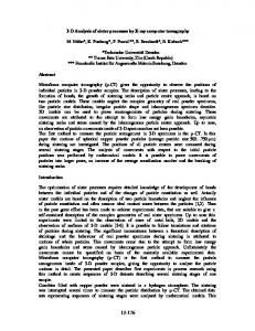
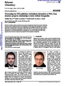
3. STEREO VIDEO RECORDING AND PROCESSING HARDWARE Our hardware consisted of: • one standard PC (Intel Core2Quad E6600, 3 GB Ram, 500 GB Hard drive) • two Sony SR-E1 HDV Handycam cameras (shown in figure 1-1) • a homemade rack consisting of metal profiles and two servomotors for adjusting convergence (as shown in figure 1-2) • a self-made remote control to maintain camera synchronicity via the LANC protocol (assembly described in Vrancic14 ) with support for the modulation of serial GPS data into audio signals and to control the servo motors (shown in figure 1-3)
Figure 1. Our Camera System. 1: Sony SR-E1 HDV Handycam cameras. 2: Rack consisting of metal profiles and two servomotors. 3: LANC controller for camera synchronicity etc.
The camera system is depicted in figure 1. The most important feature is the LANC remote control. When following Vrancic14 this remote control is easy and straightforward to create. With the controller, it is possible to synchronously use all camera functions, such as play, record, stop, zoom and focusing, just to mention a few. Moreover, it displays the temporal offset between cameras in microseconds. The servomotors may be used for controlling the degree of convergence of both optical axes. Also the stereobase may be altered by a range of 57 2
cm from 8 cm to 65 cm. The whole system has a weight of 3.5 kilogram. A carrying strap makes the system easily portable. Measuring global positioning system coordinates is also possible with this rack, whereas the data will be stored synchronously to the images through modulation into one of the five audio channels of one camcorder. This feature is realized by a serial to audio converter. For further information to this system please refer to Blenn.1 The processing hardware represents standard consumer capabilities even not specialized for video handling. Because our cameras are recording each to their own harddrive we are able to copy the left and right view via standard USB to the used PC. Solving the migration of video from the cameras to the computer via different ways will also work because our software expects all data to be accessible at the local file system.
4. WORK FLOW FOR ACQUIRING STEREO-VIDEO WITH CONSUMER HARDWARE To make our technique function optimally, it is necessary to follow a certain work schedule when acquiring the stereomovies. We found that this is the best way to minimize later processing.
4.1 Raw video material acquisition With the described rack, film making is nearly as simple as recording monoscopic video. When acquiring stereo videos one have to consider the rules of stereoscopy2 which apply to stereo-photography and stereo movie making. Additional problems of synchronicity may happen. Once recorded a fast movement with asynchronous shutter it is very hard to eliminate the occurring effects afterwards via image processing. Also the hints given in Criado8 should be observed. Large contrasts for example lead to ghosting effects during the projection no matter which projection system is used. Obligatory, the cameras have to have the same default values like shutter, automatic focusing or white balance shift. Besides it should be mentioned that zooming actually is equivalent to a virtual change of the stereobase. It should not be done for a satisfying three dimensional projection. Moreover, zooming or focusing manually are electronically controlled by propagation times of the stepping motors and not by concrete position values. This implies that subsequent back and forth zooming or focusing leads to accumulated asynchronicities between the cameras. We found that starting the acquisition with maximum or minimum zoom values is best. The usage of a predefined storybook is a convenient way to keep all relevant constraints in mind. The storyboard may also be used to retain parameters during recording like degree of convergence or stereobase.
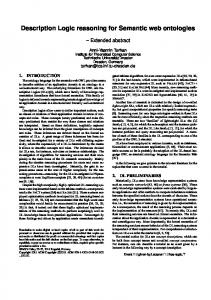
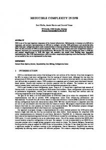
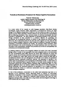
4.2 Automatic stereo video preprocessing After making the two video streams accessible at the processing PC, our automatic preprocessing step may begin. The step includes deshaking, adjustment of zero parallax plane, correction of the toe-in - keystone effects and the creation of an stereo format like side-by-side, interlaced or anaglyph and encoding the resulting images. The effect of keystone and epipolar geometry is described in Fusiello.10 As shown in figure 2a the vertical parallax arising from convergent recording setup depicted in figure 2c will lead to a vertical parallax problem when projecting the images without rectification. The parallel recording geometry shown in figure 2d in contrast leads to no errors as producing a set of images shown in figure 2b. For simplification the geometry in these figures assumes pinhole cameras. To our knowledge all existing stereo projection systems are working through projecting both images through different technologies over each other onto one visible plane. The deshaking manages the alignment of both views through calculation of optical flow for some feature points and the correspondences between the views. The underlaying assumption of the technique we are using is defined by the need for knowing or calculating the epipolar geometry of the stereoscopic views. As basis, the geometry between feature points has to be defined through horizontal lines in both views which have to have the same height. This means that errors occurring through wiggling of one camera relative to the others has to be eliminated. Those errors are occurring often when using consumer or home-build camera racks. In figure 3 the problem of a shaking camera (the right one) relative to the left one, is depicted.
3
vertical parallax left image (Il)
a)
b) left image (Il)
right image (Ir)
c)
right image (Ir)
d)
optical axes
optical axes
right image plane left image plane
kfocal
left image (Il) left camera (Cl)
stereobase
right camera (Cr)
length
kfocal
right image (Ir)
left image
stereobase right left camera camera (Cr) (Cl)
length
right image (Ir)
Figure 2. vertical parallax error occurring through convergent (toe-in) recording
In the sequence of left view images pi denotes a member of the set of feature points corresponding to qi in the right image sequence. The feature points are extracted from the video sequences with the Shi-Tomasi edge detector which is a standard technique contained in OpenCV. Feature point correspondences are found with the Lucas-Kanade optical flow also contained in OpenCV as a default technique. We then filter the correspondence pairs depending on their parallaxes. The horizontal parallax between pi and qi (earlier referred to as the total height error) is given by h = pix − qix , and the vertical parallax as v = piy − qiy . We keep only those correspondences per image pair that have parallaxes smaller than the standard deviation in horizontal and vertical direction. All other correspondences ignored as they can be considered as outliers. With a sufficiently large set of point correspondences between the views the compensation of the relative motion between the left(Cl ) and right (Cr ) camera can be realized. To obtain the standard stereo setup where epipolar lines are parallel and share the same y components, we assume that only the right camera moves with respect to the fixed left camera. We therefore look for an image warping matrix H which maps the image of the right camera Ir to a corrected image Ir0 . We assume H as Hx1 Hx2 Hx3 = 0 Hx Hy3 = Hy H = Hy1 Hy2 (1) Hw1 Hw2 Hw3 = 1 Hw as a homography (implying Hw3 = 1). This is necessary to obtain a well-posed problem. Without knowledge about the 3D scene layout and camera calibration data, the correct relation between the scene pixels the problem would be ill-posed. However, if Cr only rotates around its optical camera center, assuming H as a homography also holds true in a strict sense. 4
Sequence of six images from left view
Sequence of six images of right view
time
qi(x,y) feature corresponding to pi
time
feature pi(x,y)
Parallax pi - qi vertical
time horizontal
Figure 3. parallax error occurring through wiggle of right camera relative to the left. T
T
After applying H to Ir corresponding points pi = (pix piy ) ∈ Il and qi = (qix qiy ) ∈ Ir shall share the hH ,q i 0 same y component Hqi = qi0 shown in figure 4. This requires piy = qiy = (Hqi )y = hHwy ,qii i and thus leads to the minimization problem: �2 n � X hHy , qi i = piy − min (2) Hy1 ,Hy2 ,Hy3 ,Hw1 ,Hw2 hHw , qi i i=1 Due to its nonlinear form we solve the problem using the Levenberg-Marquardt algorithm. The optimization provides us with the 2nd and 3rd row of H. Taking into account that H can be decomposed into a projective
H(Ir)
left image (Il)
pi(x,y) qi(x,y) q|i(x,y) = H(qi(x,y))
right image (Ir)
Figure 4. Relationship of left, right and transformed right image through correspondences.
5
and an affine part
Hy2 − Hy3 Hw2 H ≈ Ha Hp = Hy1 − Hy3 Hw1 0
Hy3 Hw1 − Hy1 Hy2 − Hy3 Hw2 0
0 1 Hy3 0 1 Hw1
0 1 Hw2
0 0 1
(3)
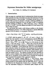
(Hx1 Hx2 ) can be derived as the vector perpendicular to (Hy1 Hy2 ). Since we have no information about the relation between the pix and qix we assume constant Hx3 = 0. Further research effort is necessary to compensate for horizontal motion as well. Figure 5 shows rectification results produced by our algorithm. As one can see, y components between corresponding image points are equalized. After correcting the views with respect to each other the features are used to smooth the whole wiggle of the video. The dewiggling is done in two steps. It is based on the collective position average of all feature points. This leads to a center of feature points for each image, called ciR and ciL . We look at center position subsequences over the last two- and next two images of each perspective (ci−2 , ci−1 , ci , ci+1 , ci+2 ). In these sequences horizontal high frequence motions are identified and removed, for each image separately in order to leave the disparity unchanged. The smoothing procedure then translates each image around its center by interpolation. By looking at the feature center of both views ci = 0.5(ciR + ciL ) the same is done for the vertical direction. The same function may also be used if the zero parallax plane should be altered by minimizing the horizontal deviation through just taking the horizontal parts in account.
4.3 Image completion When applying a perspective transformation to the right image, regions with no image information near the boundaries may occur. Those regions are located at the boarder of the translated image and can be filled using the respectively other view. Translating the left image using correspondences to equalize features located on the right image makes it possible to keep the original image size. Of course the filled parts of the images does not contain any depth information and are looking like layers in depth. In some scenes this effect is highly noticeable if image structures occur. For example where sky, concrete or for example grass occurs in those regions the result does not interfere with the full stereoscopic image.
4.4 The Software at a Glance The whole program is available for free and can be downloaded (including source code) from the websites of the chair for Computer Graphic and Visualization∗ , Faculty of Computerscience, TU-Dresden. The software is ∗
www.inf.tu-dresden.de/cgv
Figure 5. Shaken and Deshaken images after homography application, alpha blended and annotated by Point correspondences(black lines)
6
Figure 6. The graphical user interface of the software
designed using the Open Source Computer Vision15 library, the Fast Light Toolkit (FLTK)16 and the LevenbergMarquardt nonlinear least squares algorithms in C17 using the C++ programming language. For checking the result in detail several preview modes are available like anaglyph, previewing of an difference image or even the calculation of a disparity map. Images produced by this modes can also be saved to harddrive as single images or as videostream. It is possible to load two video files or one file containing side-by-side images. All movies playable with the systems standard videoplayer may be used. Internally the software uses the side-by-side format but encoding with standard codec’s installed at the system in side-by-side, anaglyph as video or image data is possible. We would suggest to use the side-by-side format for storing Stereovideos. At once because standard video codecs may be used for compression and at second postprocessing steps are way more simple when working with 2 full sized images next to each, than for example working with interlaced formats. All operations are done using the original input data. The preview window displays a smaller image but when storing data back on to the harddrive the original imagesize will be saved. Because of that interlacing artifacts may be visible at the preview window, but will be eliminated when saving videos or images. In figure 6 the graphical user interface is shown. All parameters can also be altered manually like the selection of first synchronous recorded images of the views. If a scene was recorded convergent we suggest to define the degree of convergence and the focal length of the cameras. Then the rectification of both views is applied like described in Fusiello et al.10 When running the Software using Microsoft Windows its possible to select the desired codec for compression.
5. RESULTS The main features of the techniques used by our tool are: • creation of stereoscopic images and videos with no vertical parallax, • the ability to use wiggling videos, • producing stereoscopic movies with moving (carrying) camera rig, • generation of different stereo video formats,
7
• calculation of disparity maps. Some problems may arise, because the definition of feature points does not always provide convincing results. This may lead to unexpected and unusable results because most of the processing is done using those correspondences. Also it is possible that no features will be found resulting in no processing of views. So for homogeneous image contents where no features can be found the algorithm won’t work. But such scenes in most cases there will be no stereoscopic viewable content. Because of the fact, that fitting of the described homography does not concern about horizontal alignment of features, its possible, that the fitted view may be translated to the left or right. Actually this problem is handled by estimation of zero parallax plane and the image sequence analysis. The generation of different stereo formats, calculation of depth field and possibility of storing this converted video material enables the user to feed different projection systems. Also the usage for further processing of the material performs more easy.
6. CONCLUSION AND FUTURE WORK With our preprocessing step it is possible to reconstruct views of stereoscopic action movies into an stereoscopic viewable format. The whole process works quite robust against outliers and the generated stereoscopic videos are viewable without a breakdown of the stereo impression or ghosting artefacts. For stereoscopic amateur movie makers, it is possible to record movies carrying the camera rig by hand. The assumption that the wiggling camera rotates only around its optical center is not always given, and for this circumstance the purpose of future work will be the rectification with other centers of rotation. Because estimating homographies is a quite fast and working technique this can be facilitated by estimating different planes of depth in the corresponding images. Then an appropriate technique of interpolating is needed. For future work another possibility of image deshaking will be tested maybe trough using methods like described in “Content-Preserving Warps”.18
REFERENCES 1. N. Blenn, “Entwicklung eines portablen stereo-videoaufnahmesystems fr die prsentation auf einer stereoprojektionswand.” Diploma thesis at TU Dresden, 2007. www.inf.tu-dresden.de/index.php?node id=540. 2. I. S. UNION, “The three golden rules of stereo (3d) photography.” Web page, 2009. http://www.stereoscopy.com/isu/goldenrules.html [as of: 05/18/2009]. 3. A. J. Woods, T. Docherty, and R. Koch, “Image distortions in stereoscopic video systems,” in Proc. SPIE: Stereoscopic Displays and Applications IV, 1915, pp. 36–47, 1993. 4. G. Thalin, “Deshaker.” Web page, 2008. http://www.guthspot.se/video/deshaker.htm [as of: 12/10/2009]. 5. Dynapel, “Steadyhand.” Web page, 2004. http://www.dynapel.de [as of: 04/04/2004 discontinued]. 6. N. Holliman, C. Baugh, C. Frenk, A. Jenkins, B. Froner, D. Hassaine, J. Helly, N. Metcalfe, and T. Okamoto, “Cosmic cookery: making a stereoscopic 3d animated movie,” Stereoscopic Displays and Virtual Reality Systems XIII 6055(1), SPIE, 2006. 7. S. Schneider, “How to simulate an off-axis camera to produce correct stereo pairs in blender.” Web page, 2009. http://noeol.de/s3d/ [as of: 10/18/2009]. 8. E. Criado, “Stereoscopic image production: Live, cgi, and integration,” in Proceedings of the SPIE: Stereoscopic Displays and Virtual Reality Systems XIII, 6055, pp. 24–33, 2006. 9. R. S. Allison, “The camera convergence problem revisited,” Stereoscopic Displays and Virtual Reality Systems XI 5291(1), pp. 167–178, SPIE, 2004. 10. A. Fusiello, E. Trucco, and A. Verri, “A compact algorithm for rectification of stereo pairs,” Machine Vision and Applications 12(1), pp. 16–22, 2000. 11. C. Loop and Z. Zhang, “Computing rectifying homographies for stereo vision,” in Computer Vision and Pattern Recognition, 1999. IEEE Computer Society Conference on., 1, pp. –131 Vol. 1, 1999.
8
12. R. I. Hartley, “Theory and practice of projective rectification,” Int. J. Comput. Vision 35(2), pp. 115–127, 1999. 13. R. Hartley, R. Gupta, and T. Chang, “Stereo from uncalibrated cameras,” in Computer Vision and Pattern Recognition, 1992. Proceedings CVPR ’92., 1992 IEEE Computer Society Conference on, pp. 761–764, Jun 1992. 14. D. Vrancic, “3d lanc master, user manual,” 2007. Department of Systems and Control, J. Stefan Institute, Ljubljana. 15. Intel, “Opencv.” Web page, 2000. http://sourceforge.net/projects/opencvlibrary/ [as of: 06/17/2009]. 16. B. Spitzak, “Fast light toolkit.” Web page, 2008. http://www.fltk.org/ [as of: 10/18/2009]. 17. M. Lourakis, “levmar: Levenberg-marquardt nonlinear least squares algorithms in C/C++.” [web page] http://www.ics.forth.gr/~lourakis/levmar/, Jul. 2004. [Accessed on 31 Jan. 2005.]. 18. F. Liu, M. Gleicher, H. Jin, and A. Agarwala, “Content-preserving warps for 3d video stabilization,” in SIGGRAPH ’09: ACM SIGGRAPH 2009 papers, pp. 1–9, ACM, (New York, NY, USA), 2009.
9