Oct 10, 2005 - University of California, Irvine. Irvine, CA 92697-3425, USA. (949) 824-8059. {sabdi,gajski}@cecs.uci.edu. Abstract. Increase in system level ...
A Tool for Functional Verification of System Level Model Refinements Samar Abdi and Daniel Gajski
Technical Report CECS-05-15 October 10, 2005 Center for Embedded Computer Systems University of California, Irvine Irvine, CA 92697-3425, USA (949) 824-8059 {sabdi,gajski}@cecs.uci.edu
Abstract Increase in system level modeling has given rise to a need for efficient functional validation of models above cycle accurate level. This paper presents a tool for comparing system level models, before and after a refinement. Verifiable refinements include mapping functionality in the specification to platform components, static scheduling of functions mapped to a component and routing of transactions across components. The verification tool starts by abstracting the input models into a control and data dependency graph representation. A series of functionality preserving transformations is then applied to the graphs in order to normalize them. Finally, the normalized graphs are checked for isomorphism and a decision on the equivalence of models is returned. Experimental results on industrial examples demonstrate the feasibility and the efficiency of this verification technique.
1
Contents 1. Introduction
1
2. SL Modeling and Refinement 2.1 Excutable Performance Model . . 2.2 Abstract Functional Model . . . . 2.2.1 Model Algebra . . . . . . 2.2.2 Deriving Functional Model 2.3 Model Refinements . . . . . . . . 2.3.1 Replacements . . . . . . . 2.3.2 Rearrangements . . . . . .
. . . . . . .
1 1 2 2 2 3 3 3
3 Refinement Verification 3.1 Equivalence Notion . . . . . . . . . . . . . . . . . . . . . . . . . . . . . . . . . . . . . . . . . . . . . . . . 3.2 Verification technique . . . . . . . . . . . . . . . . . . . . . . . . . . . . . . . . . . . . . . . . . . . . . . .
3 3 4
4 Model Normalization 4.1 Flattening and Link Resolution 4.2 Model Transformation Laws . 4.2.1 Identity Elimination . 4.2.2 Control Relaxation . . 4.2.3 Control Elimination . 4.2.4 Streamlining . . . . . 4.2.5 Condition bubbling . .
4 4 4 4 4 5 5 5
. . . . . . .
. . . . . . .
. . . . . . .
. . . . . . .
. . . . . . .
. . . . . . .
. . . . . . .
. . . . . . .
. . . . . . .
. . . . . . .
. . . . . . .
. . . . . . .
. . . . . . .
. . . . . . .
. . . . . . .
. . . . . . .
. . . . . . .
. . . . . . .
. . . . . . .
. . . . . . .
. . . . . . .
. . . . . . .
. . . . . . .
. . . . . . .
. . . . . . .
. . . . . . .
. . . . . . .
. . . . . . .
. . . . . . .
. . . . . . .
. . . . . . .
. . . . . . .
. . . . . . .
. . . . . . .
. . . . . . .
. . . . . . .
. . . . . . .
. . . . . . .
. . . . . . .
. . . . . . .
. . . . . . .
. . . . . . .
. . . . . . .
. . . . . . .
. . . . . . .
. . . . . . .
. . . . . . .
. . . . . . .
. . . . . . .
. . . . . . .
. . . . . . .
. . . . . . .
. . . . . . .
. . . . . . .
. . . . . . .
. . . . . . .
. . . . . . .
. . . . . . .
. . . . . . .
. . . . . . .
. . . . . . .
. . . . . . .
. . . . . . .
. . . . . . .
. . . . . . .
. . . . . . .
. . . . . . .
. . . . . . .
. . . . . . .
. . . . . . .
. . . . . . .
. . . . . . .
. . . . . . .
. . . . . . .
. . . . . . .
. . . . . . .
. . . . . . .
. . . . . . .
. . . . . . .
. . . . . . .
. . . . . . .
5 Experimental Results
5
6 Conclusion and Future Work
6
i
List of Figures 1 2 3 4 5 6 7 8 9 10
The platform model and its corresponding functional abstraction The refined SL platform model . . . . . . . . . . . . . . . . . . Steps in refinement verification . . . . . . . . . . . . . . . . . . Transaction link resolution . . . . . . . . . . . . . . . . . . . . Identity elimination law . . . . . . . . . . . . . . . . . . . . . . Control relaxation law . . . . . . . . . . . . . . . . . . . . . . Control elimination law . . . . . . . . . . . . . . . . . . . . . . Streamlining law . . . . . . . . . . . . . . . . . . . . . . . . . Condition bubbling law . . . . . . . . . . . . . . . . . . . . . . Performance of verification tool for various refinements . . . . .
ii
. . . . . . . . . .
. . . . . . . . . .
. . . . . . . . . .
. . . . . . . . . .
. . . . . . . . . .
. . . . . . . . . .
. . . . . . . . . .
. . . . . . . . . .
. . . . . . . . . .
. . . . . . . . . .
. . . . . . . . . .
. . . . . . . . . .
. . . . . . . . . .
. . . . . . . . . .
. . . . . . . . . .
. . . . . . . . . .
. . . . . . . . . .
. . . . . . . . . .
. . . . . . . . . .
. . . . . . . . . .
. . . . . . . . . .
. . . . . . . . . .
. . . . . . . . . .
. . . . . . . . . .
2 3 3 4 4 4 5 5 5 6
A Tool for Functional Verification of System Level Model Refinements Samar Abdi and Daniel Gajski Center for Embedded Computer Systems University of California, Irvine
Abstract
tory, then the platform, or the mapping of the application on the platform, is modified and a new model is produced and evaluated. This process may be repeated several times before a final implementation is decided, and each intermediate models is functionally verified as it is refined. There is a huge body of research in functional equivalence verification of high level system modes, mostly from the software community. Symbolic simulation has been used in [6] to verify equivalence of terminating embedded software. In [11], the authors use textual comparisons of models to check consistency. Checking of C models against their verilog implementations has been proposed in [5] using bounded model checking. Correct-by-construction techniques have been implemented for system design, notable in ForSyde [12] tool set. The need for high level modeling of embedded systems has given rise to system level design languages (SLDLs) such as like SystemC 2.0 [2] and SpecC [7]. This has led to research being directed towards modeling and verification at system level in order to verify the correctness of design steps. Traditional software model checking [10] and bounded model checking [4] allow property verification of high level models written in C-like languages. However, to the best of our knowledge, there has been little work in refinement verification of system level models using model transformations.
Increase in system level modeling has given rise to a need for efficient functional validation of models above cycle accurate level. This paper presents a tool for comparing system level models, before and after a refinement. Verifiable refinements include mapping functionality in the specification to platform components, static scheduling of functions mapped to a component and routing of transactions across components. The verification tool starts by abstracting the input models into a control and data dependency graph representation. A series of functionality preserving transformations is then applied to the graphs in order to normalize them. Finally, the normalized graphs are checked for isomorphism and a decision on the equivalence of models is returned. Experimental results on industrial examples demonstrate the feasibility and the efficiency of this verification technique.
1. Introduction System level (SL) design is being adopted to combat the rising complexity of modern embedded designs. Design methodologies now involve several modeling stages and platform/application updates before a cycle accurate implementation is considered. At each step, the system model is transformed to reflect the design decision made at that step. However, it is imperative that the functionality of the model is preserved as the design progresses through these incremental refinements. In other words, we need to validate if two models, before and after the implementation of a design decision, are functionally equivalent. In this paper, we present a technique and implementation results for functional validation of model refinements resulting from SL design decisions. A possible SL design methodology is as follows. We start by creating an executable model of the system that includes the application and the mapping of the application onto components of the platform architecture. The model is executed and performance metrics like area, power and speed are gathered. If the implementation is not satisfac-
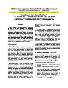
2. SL Modeling and Refinement 2.1 Excutable Performance Model A typical executable performance model is shown in Figure 1(a). The platform consists of a processor (Proc.) connected to Bus1 along with two hardware components (HW1 and HW2). Communication elements such as arbiter and interrupt controller (IC) allow safe and synchronized communication between the processor and the HW components. The architecture in the model is captured using hierarchy (a parallel composition of components) and signals and channels for wires and bus interfaces. The application itself is captured by instantiating behaviors inside the appropriate component behavior. For instance, behaviors b1 and b2 of 1
vsp
System
Proc.
HW1
Task Sched.
1
1
b3 HW1
b1
b2
Driver
1
Proc.
b4 IC
vsp 1
l2 1
Bus I/F b1
l1 Bus1
b2
Bus 1
1
b3
b3
1
q
1
l2 b4
vtp
HW2 Bus I/F
Arbiter
vsp
1
l1 v
1
HW2
vsp
vtp
!q
vtp
b5 1
vtp
(b) Abstract functional model
(a) Performance Model
Figure 1. The platform model and its corresponding functional abstraction the application are mapped to Proc. as seen by the behavioral hierarchy.
Control dependencies are graphically represented using directed broken edges between behaviors nodes (round edged boxes) and conditions nodes (circles). A control dependency of the form After b1 executes, if condition q is true, then b2 may execute can be represented with three nodes for b1 , b2 and q and two control edges (b1 , q) and (q, b2 ). A more complex control dependency of the form After b1 through bn have executed, if condition q is true, then b may execute can be represented with n + 1 control edges (b1 , q),...,(bn, q) and (q, b). Communication is possible either through variable (represented as box) read/write or channel (represented as ellipses) transactions. A variable read is represented with a solid edge from the variable node to a behavior node. Similarly, a variable write is represented with a solid edge from behavior to variable node. Transaction links are represented with a pair of solid edges, from sender behavior to channel and channel to receiver. Both edges are labeled with the transaction link address. Transactions follow the rendezvous protocol (Hoare semantics [9]) in contrast to nonblocking read/write of variables. Transactions links may share a channel and are distinguished by their addresses.
2.2 Abstract Functional Model For functional verification of the system, we are not interested in the implementation details. Therefore, the performance model may be abstracted into a purely functional model. We now look at the syntax, semantics and derivation of the functional model. 2.2.1 Model Algebra The performance model of the system is typically written in a system level design language (SLDL) like SystemC [2]. The abstract functional model can be expressed using a much simpler representation we will refer to as Model Algebra (MA)[3]. MA uses simple objects and composition rules to express a system model. The objects are: Behavior, to capture the functionality Channel, to capture the bus structure Condition, to capture control flow Port, for hierarchy Variable, for storage Address, to distinguish bus transaction links The composition rules of MA allow us to create behavioral hierarchy, control dependencies and data dependencies. Behaviors (represented as round edged boxes) can be either hierarchical, created using composition rules, or leaf. All leaf level behaviors are treated as uninterpreted functions. A special type of behavior called the identity behavior has the property that its output is the same as its input.
2.2.2 Deriving Functional Model Given the syntax of Model Algebraic representation, we derive the abstract functional model of our example as shown in Figure 1(b). The bold grey arrows show the abstraction of the objects in the performance model in Figure 1(a) into objects in the abstract model on the right hand side. All hierarchical behaviors have unique start and terminate identity behaviors called virtual starting point (vsp) and virtual terminating point (vtp) respectively. Leaf behaviors are copied 2
as is since they are treated as uninterpreted functions. Sequentiality and loops inside HW1 are modeled using control dependencies as shown. Note the abstraction of the behaviors and the task scheduler inside Proc. using the control flow of MA. Both behaviors b1 and b2 are allowed to start simultaneous after vsp. However, the Proc. behavior terminates only after both b1 and b2 have terminated. All communication implemented in the performance model (using bus signals, arbiter, IC, drivers and bus interfaces) is abstracted into high level transaction links l1 and l2 implemented on the channel labeled Bus1 . Finally, the top level system is abstracted as a parallel composition of hierarchical component behaviors.
flow or the routing of transactions. Scheduling of behaviors inside a component, moving a behavior from one component to another and changing the route of inter-behavior communication are typical examples of rearrangements. Figure 2 shows an updated platform derived from the platform in Figure 1(a). We can see that a new bus, Bus2, has been added, behavior b4 has been moved into a new HW component, HW3, and the behaviors inside Proc. have been serialized. In this paper, we will focus on the verification of rearrangements.
2.3 Model Refinements
In order to verify the functional correctness of a refinement, we must first define a notion of equivalence. This equivalence notion is defined for the MA representation of a model. We then show how functionality preserving transformations can be used to check if two models, before and after a refinement are equivalent.
3 Refinement Verification
Refinement is the general term we will use for modifications to either the platform architecture, or the implementation of the application on the architecture. In this section, we consider two basic types of SL model refinements.
3.1 Equivalence Notion 2.3.1 Replacements Our notion of functional equivalence is based on the trace of values that the variables hold during model execution. Consider a variable v1 in a given model M1 . Assume M1 is refined to a new model M2 , such that variable v2 in M2 is expected to hold the same values as v1 was holding during execution of M1 . We say that the pair (v1 , v2 ) are corresponding variables for M1 and M2 . We further define τ(v, M, Init) to be the partial order trace of all values assumed my variable v when model M is executed with an initialization Init of all M’s variables. Let Init1 and Init2 be intializations of M1 and M2 , respectively, such that the corresponding variables of M1 and M2 have the same intial value. Models M1 and M2 are said to be functionally equivalent with respect to pair (v1 , v2 ) if and only if τ(v1 , M1 , Init1 ) = τ(v2 , M2 , Init2 ) The above definition of equivalence requires us to define how the corresponding variables in the original and refined model will be determined. In certain refinements extra variables may be created. We consider all variables written by non-identity behaviors for equivalence of models.
Replacements are used to either model the application in greater detail (to improve confidence in estimation) or to change the platform (to improve some performance metric). Examples include modeling a behaviors a cycle accurate level, changing the bus protocol, changing the precision, arbitration policy, task scheduling policy etc. In our methodology, verification of replacements requires property checking to correctly abstract the functionality from the model. For instance, if the bus arbitration policy is changed, we need to check if the new policy still forces mutually exclusive access to the bus. Proc.
HW1
b1 b2
b3 Bus1 I/F
IC
Driver
bridge
Bus I/F
Bus2 I/F Bus 1 Bus 2 Arbiter
HW2
Bus I/F
Bus I/F
b5
b4 HW3 Original SL Model (A)
Figure 2. The refined SL platform model
Functional Abstraction
Graphical Representation (A)
Graph Normalization
Model Refinement
Refined SL Model (B)
Normalized Model A
Isomorphism Check
Functional Abstraction
Graphical Representation (B)
Graph Normalization
Normalized Model B
2.3.2 Rearrangements Figure 3. Steps in refinement verification
These type of refinements include modifications that do not alter the leaf level behaviors, only rearranging the control 3
Equivalent / Not Equivalent
3.2 Verification technique
until e has executed, and vice versa. After link resolution, the model turns into a control and data dependency graph of behaviors, condition nodes and variable nodes.
The verification tool flow is shown in Figure 3. First, we abstract the SLDL model into a graphical MA representation. The MA representation then undergoes a series of transformations until no more transformations can be applied. The final model is said to be normalized. The normalized models are then checked for isomorphism. There are two key requirements for such a verification technique to succeed. The first requirement is the soundness of the transformation laws that are used to normalize the model. Soundness means that each transformation must produce an equivalent model, according to the equivalence notion defined above. The second requirement is that the normalization algorithm must always produce isomorphic normal forms for any two models that can be proven equivalent using the transformation laws. In the following section, we will discuss the transformation laws, but refer the reader to our technical report [3] for detailed proofs.
4.2 Model Transformation Laws The following transformation laws are used to normalize the model. Note that each law is symmetric (as indicated by bidirectional arrow), but the normalization algorithm applies the law from LHS to RHS. b1 v1
q1
b1
qm
e
v1
q1& q1'
qm& qn'
v1' q1'
b2
qn'
b2
Figure 5. Identity elimination law
4 Model Normalization The normalization procedure consists of two steps. First the hierarchy is flattened and the transaction links are resolved, resulting in a control and data dependency graph. Then a series of transformations (derived from transformation laws) are applied to normalize the graph. v
The identity behavior does not modify any outputs of non-identity behaviors and therefore its execution is unobserved during model simulation. First the variable read and the variable written are merged.Then all incoming control nodes are cross multipled with outgoing control to produce new control nodes. The condition of the resulting nodes is obtained by ANDing the conditions of the original node. Thus we have identical control paths in the LHS and the RHS as illustrated in Figure 5.
v
e
c
e'
e
v'
q1
4.2.1 Identity Elimination
qn
q1'
qm'
q1
e'
v'
qn
q1'
qm'
Figure 4. Transaction link resolution
e1
e1
1
1
b1
b1
b1
q
q
q
b2
b2
b2
1
1
e1
e1
4.1 Flattening and Link Resolution The MA representation is flattened by recursively modifying port mappings and control flow relations. Consider a hierarchical behavior bh which a sub-behavior of bh . Consider port ph of bh . A sub-behavior of bh reading from a variable v in b via port ph will have a direct read relation from v after bh is flattened. Similar flattening methods are used for variable writes and channel transactions. Transaction links in the flattened model are resolved as illustrated in Figure 4. Note that we allow the sender and receiver of a transaction to be identity behaviors only. The transaction link in the LHS ensures that at the end of the transaction, v′ will be a copy of v. It also ensures that e does not terminate before e′ starts executing and vice versa. The above two properties are also followed in the RHS model, where e directly writes to v′ . Also, the additional control dependencies ensure that no behavior following e′ is executed
Figure 6. Control relaxation law
4.2.2 Control Relaxation A behavior b1 is said to dominate b2 if b1 executes at least once before every execution of b2 . The domination rela4
tionship will be graphically shown using broken thick grey arrows. If a control relation from b1 to b2 with condition q is such that b1 dominates b2 and both q and b2 do not have any data dependencies on b1 or q, then the false control dependency may be relaxed to allow b2 to execute in parallel with b1 . The control relaxation law illustrated in Figure 6, first pads b1 and b2 with identity behaviors using the inverse of the identity elimination law. Then the control dependencies are modified as shown.
(a)
q
(b)
q'
q'&q
b
b q
q1
qn
b1
bn q
b1 (a)
b1
b2
X
q
(b)
b1
b2
q1&q
qn&q
b1
bn 1
Figure 9. Condition bubbling law
X
b3
b1
1
b2 q
b3
1
4.2.5 Condition bubbling Consider a condition node q 6= 1. Let there be an edge from b to q and from q′ to b. If there is no data dependency from b to q, then the condition of q can be ANDed with condition of q′ and condition of q can be set to 1. Thus the control condition of q is evaluated earlier, as shown in Figure 9.
b2
q
q
b3
b3
Figure 7. Control elimination law
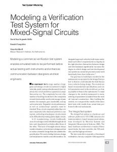
5 Experimental Results A verification tool based on the technique on Section 3.2, was written in C++ for checking refinement of SpecC models. The functional abstraction module was used to derive the Model Algebraic representation from a SpecC Model. The transformation rules in Section 4 were then used to normalize this representation into a control and data dependency graph. The normalized graphs for the original and refined model were compared using a simple graph isomorphism checker implemented within the verification tool. A BDD manipulation package CUDD [1] was used to maintain the boolean functions for the condition nodes. The verification tool has been tested on a wide variety of applications and refinements. We present here, results from two applications from the multimedia domain. The first application is a GSM voice codec application [8] ( 12K lines of SpecC code) for cellular phones. The second application is a module within an MP3 decoder ( 8K lines of SpecC code). Three types of rearrangement refinements were tried for each application. The first refinement, behavior mapping, was used to move some behavior from one component to another. This refinement resulted in a different behavioral hierarchy and extra behaviors and synchronization to preserve the functionality of the design. The second refinement, communication scheduling, was used to reorder behavior execution inside components so as to change the bus congestion. The final refinement, transaction routing, was used to change the bus architecture and route transactions via a bridge. The table in Figure 10 shows results for the verification
4.2.3 Control Elimination If two behaviors b1 and b2 have edges to a control node q leading to b3 , then if b1 dominates b2 and b3 does not dominate b2 (Figure 7(a), the edge b1 , q may be removed. If b3 does dominate b2 , then the edge b2 , q may be removed. This law is illustrated in Figure 7. vsp
bx
bw
by q
q
b
bx q
b
Figure 8. Streamlining law
4.2.4 Streamlining Let two control nodes q1 and q2 with identical control conditions have edges leading to the same behavior b, and q1 and q2 both have an edge from bx . Let there be another edge from bw (6= bx ) to q1 and from by (6= bx ) to q2 . If by is VSP or dominated by VSP and bw is same as b or dominated by b, then the two control nodes q1 and q2 can be merged into a node with an edge from bx , as shown in Figure 8. 5
Application
Voice Codec
MP3 Decoder Module
Normal Model
Refinement Type
Model before normalization
Behavior Mapping
B:148, D:127, Q:161; CD:332, DD:429 B:188, D:138, Q:202; CD:439, DD:453
Comm. Scheduling Transaction Routing
B:188, D:138, Q:202; CD:439, DD:453 B:188, D:138, Q:202; CD:428, DD:453 B:188, D:138, Q:202; CD:428, DD:453 B:204, D:144, Q:221; CD:463, DD:470
Behavior Mapping
B:75, D:60, Q:91; CD:156, DD:146 B:92, D:76, Q:132; CD:202, DD:160
Comm. Scheduling
B:92, D:76, Q:132; CD:202, DD:160 B:92, D:76, Q:132; CD:197, DD:160 B:92, D:76, Q:132; CD:197, DD:160 B:98, D:88, Q:150; CD:224, DD:192
Transaction Routing
Number of Transaformations
Total:6131 (Flat:3994, IE:1331, B:89, CR:708, CE:14, Str:14, Bub:65) D:127, Total:7065 (Flat:4642, IE:1548, Q:115; CR:731, CE:16, Str:28, Bub:110) CD:332, DD:445 Total:7229 (Flat:4726, IE:1600, CR:727, CE:18, Str:42, Bub:110) Total: 2602 (Flat:1566, IE:602, B:54, CR:344, CE:12, Str:14, Bub:28) D:60, Total:3740 (Flat:2464, IE:812, Q:72; CR:365, CE:12, Str:24, Bub:54) CD:143, DD:141 Total:3852 (Flat:2520, IE:848, CR:371, CE:12, Str:36, Bub:54)
Verification Time (sec) 3.3 3.7 3.7 1.6 2.1 2.2
Figure 10. Performance of verification tool for various refinements
References
of aforementioned refinements on the two applications. The column Model before normalization gives statistics for the abstract functional model in terms of number of behavior nodes (B), variable nodes (D), condition nodes (Q), control dependency edges (CD) and data dependency edges (DD). The column Normal Model gives the statistics of the normalized graph. Note that normal form is unique for all models involved in the refinements. Number of transformations include transformations resulting from flattening (flat), identity elimination (IE), control relaxation (CR), control elimination (CE), Streamlining (Str) and condition bubbling (Bub). The total number of transformations is greater than the sum of the itemized transformations, since we did not include miscellaneous transformations like removal of unreachable nodes, variables without readers or writers etc. The number of transformations includes transformations performed for normalizing both the original model and the refined model. As we can see, the total verification time is in the order of a few seconds, which makes this technique very practical.
[1] CU Decision Diagram Package. Available: http://vlsi.colorado.edu/ fabio/CUDD/cuddIntro.html. [2] SystemC, OSCI[online]. Available: http://www.systemc.org/. [3] S. Abdi and D. Gajski. System Level Verification with Model Algebra. Technical Report ICS-TR-04-29, University of California, Irvine, October 2004. [4] E. Clarke, D. Kroening, and F. Lerda. A tool for checking ANSI-C programs. In K. Jensen and A. Podelski, editors, TACAS 2004, volume 2988 of Lecture Notes in Computer Science, pages 168–176. Springer, 2004. [5] E. Clarke, D. Kroening, and K. Yorav. Behavioral consistency of c and verilog programs using bounded model checking. In DAC ’03: Proceedings of the 40th conference on Design automation, pages 368–371, New York, NY, USA, 2003. ACM Press. [6] X. Feng and A. J. Hu. Cutpoints for formal equivalence verification of embedded software. In EMSOFT ’05: Proceedings of the 5th ACM international conference on Embedded software, pages 307–316, New York, NY, USA, 2005. ACM Press. [7] D. Gajski, J. Zhu, R. Domer, A. Gerstlauer, and S. Zhao. SpecC: Specification Language and Methodology. Kluwer Academic Publishers, January 2000. [8] A. Gerstlauer, S. Zhao, and D. Gajski. Design of a GSM Vocoder using SpecC Methodology. Technical Report ICSTR-99-11, University of California, Irvine, February 1999. [9] C. Hoare. Communicating Sequential Processes. Prentice Hall, 1985. [10] G. Holzmann. The model checker spin. IEEE Transactions on Software Engineering, 23(5), June 1997. [11] H. Saito, T. Ogawa, T. Sakunkonchak, M. Fujita, and T. Nanya. An equivalence checking methodology for hardware oriented c-based specifications. In IEEE International High Level Design Validation and Test Workshop, pages 274–277, October 2002.
6 Conclusion and Future Work We presented a technique to check the functional equivalence of system level models before and after different types of refinements. The main advantage of this technique is that the designer does not need to perform costly simulations after every modification to the design implementation. However, this technique is not a comprehensive solution and must be used in conjunction with property checking to verify most types of useful model refinements. Our experimental results demonstrated the practical feasibility of our verification technique on industrial examples. In the future, we will integrate a property checker in order to verify the functional abstraction of SLDL models. 6
[12] I. Sander, A. Jantsch, and Z. Lu. Development and application of design transformations in forsyde. In DATE ’03: Proceedings of the conference on Design, Automation and Test in Europe, page 10364, Washington, DC, USA, 2003. IEEE Computer Society.
7