availability of a specific input needed to users in order to perform their tasks. All those ..... //A comboBox to show the set of possible frequency. ComboBox ...
A Tool Suite for Integrating Task and System Models through Scenarios o1 , Carmen Santoro1 , and David Navarre2 , Philippe Palanque2 , Fabio Patern` 2 R´emi Bastide 1 CNUCE-CNR, Via V. Alfieri 1, 56010 Ghezzano, Pisa, Italy 2 LIHS, Universit´e Toulouse 1, Place Anatole France, 31042 Toulouse Cedex, France {navarre, palanque, bastide}@univ-tlse1.fr {f.paterno, c.santoro}@cnuce.cnr.it
Abstract. This paper presents a set of tools supporting the development of interactive systems using two different notations. One of these notations, called ConcurTaskTrees (CTT), is used for task modelling. The other notation, called Interactive Cooperative Objects (ICO), is used for system modelling. Even though these two kinds of models represent two different views of the same world (users interacting with interactive systems), they are built by different people and used independently. The aim of this paper is to propose the use of scenarios as a bridge between these two views. On the task modelling side, scenarios are seen as possible traces of activities, while on the system side, they are viewed as traces of actions. This generic approach is presented in a case study in the domain of Air Traffic Control.
1
Introduction
The research area of model-based design and evaluation of interactive applications [12] aims at identifying models able to support design, development, and evaluation of interactive applications. Such models highlight important aspects that should be taken into account by designers. Various types of models, such as user, context, and task models, have proved to be useful in the design and development of interactive applications. In particular, interactive systems are highly concurrent systems, which support several devices media and tools, and are characterised by dialogues and the presentations they provide for communicating information to users. However, to build effective presentations it is important to understand the activities that users want to perform with them. Such activities can be highly concurrent with even multi-user interactions and such concurrency is a source of flexibility but at the same time has to be carefully designed and controlled. In addition, we have to take into account that the concurrency provided to users needs to be supported by the system underneath. Thus we need not only models for specifying user activities while interacting with the system, but also C. Johnson (Ed.): DSV-IS 2001, LNCS 2220, pp. 88–113, 2001. c Springer-Verlag Berlin Heidelberg 2001 �
A Tool Suite for Integrating Task and System Models through Scenarios
89
for specifying the underlying system. Such models should allow different levels of refinement depending on the needs of the users and should be powerful enough to express all the different relationships occurring among the various components without introducing too many low-level details. Having models is not sufficient to support a formal analysis, methods and tools are strongly requested to help designers use the information contained in such models during their work. In particular, in the field of model-based approaches to human-computer interaction only recently tools supporting such approaches have started to be developed. Unfortunately, often such tools are rather rudimentary, usable only by the groups that developed them. Even less attention has been paid to the integration of models and tools developed for different purposes. In this paper we present the results of a work that aims to overcome this limitation. In particular, we show and discuss how we have reached the integration of a set of tools for task modelling with a set of tools for user interface system modelling through the use of abstract scenarios. The goal of such integration is to provide designers with an environment enabling them to see, for example, how a sequence of user tasks can be related to the specification of the behaviour of the underlying system’s interconnecting components. In the paper, after a short discussion of related works, we recall the basic concepts of the approaches and tools that we aim to integrate. Then, we discuss the architecture of the solution identified. As both the CTT and ICO notations are tool supported (the environments are respectively CTTE and PetShop), an integration tool (implemented at LIHS) based on this notion of scenarios is presented. An application example of the integrated set of tools is discussed before drawing some concluding remarks. The case study presented has been addressed in the European Project MEFISTO, which is a long-term research project dedicated to the design of safety critical interactive systems with the support of formal methods. In particular, the project has focused on the air traffic control domain from which this case study has been drawn.
2
Related Work
The use of models has often been criticised for the effort required to develop them and the difficulties in using the information that they contain to support design and evaluation. After having carefully evaluated the need for introducing a new notation, the first concern should be providing users with tools to make its use easier and more effective. The problem is that getting used to another notation involves a significant amount of effort and time spent by the potential users in order to understand features, semantics and meaning of the notation’s conventions. In addition, even when users have understood the main features of the notation, there is still the risk that their effort might be wasted if they find that using it is difficult and not really feasible or appropriate for intensive use and real case studies. Indeed, one of the strengths of a notation is the possibility of supporting it through automatic tools. Developing a formal model can be a long process, which
90
D. Navarre et al.
requires a considerable effort. Automatic tools can ease such activity and can help designers to get information from the models, which is useful for supporting the design cycle. Some research prototype was developed years ago to show the feasibility of the development of such tools, however the first prototypes were rather limited in terms of functionality and usable mainly by the people who develop them. Only in recent years some more engineered tools have been developed, in some cases they are also publicly available. For example, Euterpe [18] is a tool supporting GTA (Groupware Task Analysis) where task models are developed in the horizontal dimension with different panels to edit task, objects, actors. A simulator of task models of single user applications has been given with the support of an object-oriented modelling language [3]. Mobi-D [16] and Trident [4] are examples of tools aiming to use information contained in models to support design and development of user interfaces. In particular, in Mobi-D the designer can choose different strategies in using the information contained in task and domain model to derive the user interface design. In our work we envision a solution based on the use of two tools (CTTE and PetShop) developed to support two different types of models. The former is a tool for task modelling supporting a unique set of functionality (simulation of models of cooperative applications, comparison of task models, support of use of scenarios to develop task models, . . . ). The latter supports system models described using Petri nets in an object-oriented environment. PetShop is able to support editing of a Petri Net controlling the dialogues of a user interface even at run-time thus allowing dynamic change of its behaviour. Their integration allows thorough support to designers since early conceptual design until evaluation of a full prototype.
3
Our Approach
Various models have been proposed in the human-computer interaction field. Task and system models are particularly important when designing and developing interactive software systems. In both industrial and academic communities there is a wide agreement on the relevance of task models as they allow expressing the intentions of the users and the activities they should perform to reach their goals. These models also allow designers to develop an integrated description of both functional and interactive aspects. Within the development lifecycle of an application the task-modelling phase is supposed to be performed after having gathered information on the application domain and an informal task analysis phase. The result of the latter one is an informal list of tasks that have been identified as relevant for the application domain. After this step, in developing a task model designers should be able to clarify many aspects related to tasks and their relationships. In some cases task models are first developed and then used to drive the system design. In other cases
A Tool Suite for Integrating Task and System Models through Scenarios
91
designers have to address an existing system and need to develop a task model to better understand and evaluate its behaviour [11]. System models describe important aspects of the user interface. In this work we pay particular attention to the dialogue supported by the system: how user actions and system feedback can be sequenced. Thus, the purpose of these models is to support the analysis of the user interface system, rather than the related task model. They provide description of the objects making up the user interface and the underlying system and how they behave, whereas in the task model there is a description of the logical activities supported. There is an intersection between the aspects described by the two models (the actions that can be performed at the user interface level) but each of them also captures aspects that are not represented in the other one. The task model also describes cognitive user activities (such as deciding a strategy to find information) and the system model contains a description of the system architecture. Scenarios [5] are a well-known technique in the human-computer interaction area. They provide a description of one specific use of a given system, in a given context. They are an example of usage. Their limited scope is their strength because they can easily highlight some specific aspect and are easily understood and remembered. Thus, they can also be considered as a useful tool to compare different models and analyse their relationships. In the design process, one important goal is to check if the task model fulfills the expected requirements and if the system model matches the planned behaviour. However, what cannot be missed is checking if both two models are consistent, which means if both specifications really refer to the same user interface. This requires checking if for each user action assumed in the system model there is an actual counterpart in the task model, and each system output provided to the user has been foreseen in the task model specification. Another relevant point that has to be highlighted is that these two models can be specified by different people and in distinct moments of the design cycle of the user interface development process. Indeed, especially in real case studies sometimes the task models will be developed at first, sometimes they might be specified after the system model has already been obtained. So, we need an approach that does not have specific constraints and requirements on what is assumed to be available at a certain phase of the system design, as it can be equally used efficiently in both cases. In our approach, we used abstract scenarios as the common “lingua franca” to ensure that there is actual correspondence between what has been specified within the task model and what has been specified in the system model. The idea is to focus the attention on specific examples of usage either on the system side or on the tasks side and to check if on these simple examples of the system use such correspondence exists. Considering the task model-side, in our approach we used the ConcurTaskTrees notation for specifying tasks. The formal semantics of the operators used in this notation is in [13]. This notation allows users to explicitly express how the allocation of the different tasks has been assumed in the system design.
92
D. Navarre et al.
Such allocation could be on the user alone (user tasks), on the application alone (application tasks), on the interaction between the user and the application (interaction tasks), or if the activity is too general to be specifically allocated on each of them (abstract task). Explicit indication of task allocation is one aspect which makes the notation very suitable for designers of interactive systems, because they have to explicitly indicate which part of the interactive system (user, application, interaction between them) has to undertake each task. This aspect proves to be effective especially when both comparison and integration of different models has to be carried out, such as in our case. The notation provides the ability to specify in the task model when system support is requested on the user interface. This allows comparing and cross-checking if the task model reflects and is adequately supported by the corresponding system model. More specifically, the points that have to be carefully checked in the task model specification are the interaction and application tasks. Application tasks indicate that at a certain point during a session a specific behaviour of the system is expected. This behaviour can be expressed in terms of a specific feedback of an action the user has performed while interacting with the system; in terms of a result the system has produced after some elaboration; in terms of availability of a specific input needed to users in order to perform their tasks. All those possibilities have to be carefully supported especially if the considered domain is vast and complex as the air traffic control field considered in our case study. Such domain is composed of a number of entities that maintain a complex relationship structure, due to their internal structure and to the dynamic behaviour they follow, which has to be appropriately presented to the users.
4
A Case Study
This case study has been considered in the European Project MEFISTO which is a long term research project dedicated to the design of safety critical interactive systems, with particular attention to the air traffic control application domain. After a short overview of the case study in sub-section 4.1, this section presents the various models built in order to represent both predictive user activities and the system under consideration. Sub-section 4.2 presents the use of CTT and its environment for tasks modelling and simulation as well as the identification of scenarios from the task models. Sub-section 4.3 presents the use of the ICO formalism and its support environment PetShop for modelling and executing interactive systems. 4.1
Informal Description of the Case Study
This example is taken from a case study related to En-route Air Traffic Control with the support of data-link technologies in the ATC field. Using such applications air traffic controllers can communicate with pilots in a sector (a portion of the airspace) through digital commands. In particular, we focus on the activities related to when an aircraft changes air sector.
A Tool Suite for Integrating Task and System Models through Scenarios
93
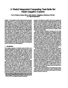
A representation of the radar image is shown in Figure 1. On the radar image each plane is represented by a graphical element providing air traffic controllers with useful information for handling air traffic in a sector. In the simplified version of the radar image we are considering, each graphical representation of a plane is made up of three components: a label (providing precise information about the plane such as ID, speed, cleared flight level, . . . ), a dot (representing the current position of the plane in the sector) and a speed vector (a graphical line from the dot which represent the envisioned position of the plane in 3 minutes). An Air Traffic Control simulator is in charge of reproducing the arrival of new planes in the sector while in reality they would be instantiated on the user interface by calls from the functional core of the application processing information provided by physical radars. Initially the radar image is empty. Each time a new plane is randomly generated it is graphically represented on the radar image. It is possible for the user to select planes by clicking on its graphical representation. Clicking on the flight representation will change its state to the Assume state meaning that the air traffic controller is now in charge of the plane. Assuming the plane changes its graphical representation as it can be seen on the right-hand side of Figure 1. Once a plane is assumed, the controller can send clearances to this plane. In this case study we only consider the change of frequency functionality corresponding to the controller’s activity of transferring a plane to an adjacent sector. When is enabled (see plane 1123 on the plane has been taken on, the button the right-hand side of Figure 1). Clicking on this button opens a menu allowing the controller selecting the new value for the frequency.
Fig. 1. A screen shot of the radar screen with planes (right-hand side, one the planes 1123 is assumed)
94
4.2
D. Navarre et al.
The ConcurTaskTrees Notation and Environment Used in the Case Study
We first introduce the notation for task modelling that has been used and the related environment. The ConcurTasktrees Notation There are various approaches that aim to specify tasks. They differ in aspects such as the type of formalism they use, the type of knowledge they capture, and how they support the design and development of interactive systems. In this paper we consider task models that have been represented using the ConcurTaskTrees notation [12]. In ConcurTaskTrees activities are described at different abstraction levels in a hierarchical manner, represented graphically in a tree-like format (see Figure 2 for an example). In contrast to previous approaches, such as Hierarchical Task Analysis, ConcurTaskTrees provides a rich set of operators, with precise meaning, able to describe many possible temporal relationships (concurrency, interruption, disabling, iteration, and so on). The notation allows designers to obtain concise representations describing many possible evolutions over a user session. The formal semantics of the operators has been given in [13]. The notation also supports the possibility of using icons or geometrical shapes to indicate how the performance of the tasks is allocated.
Fig. 2. The abstract task model of the case study
For each task it is possible to provide additional information including the objects manipulated (for both the user interface and the application) and attributes such as frequency. In addition, as in the design of complex cooperative environments more and more attention is being paid to the horizontal mechanism of coordination between different roles, ConcurTaskTrees allows designers to specify explicitly how the cooperation among different users is performed. We give an overview of the main features of the notation by commenting on two excerpts of specification from the considered case study. The activity of controlling a plane (Control a plane) is an iterative task (∗ is the iterative operator) which consists of either assuming a plane (Assume a plane task) or giving clearance to the plane (Give clearance task). Those two activities are mutually exclusive, as you can see from the choice operator [].
A Tool Suite for Integrating Task and System Models through Scenarios
95
The activity of assuming a plane is composed of deciding which plane has to be assumed (Select a plane task, the associated icon emphasizes the cognitive nature of this user task). Once this activity has been performed it is possible to select the button related to the plan (see the Enabling operator with information passing [] >>, which highlights that only after the first activity has been carried out and delivered information to the second task, the latter can be performed). In addition, the Click plane task requires an explicit action of the controller on an element of the user interface so it belongs to the category of interaction tasks and the appropriate icon has been used. The Give clearance task is composed of two different activities: Give Aborted Clearance and Give Validated Clearance, depending on whether the clearance has been aborted or not. Each of these two activities is a high-level one, whose performance cannot be entirely allocated either to the application alone, or to the user alone, or to an interaction between the user and the system: this is expressed by using a cloud-shape icon associated to the so-called abstract tasks. The specification of each of these two tasks is described in Figure 3.
Fig. 3. The concrete and detailed task model of the case study
The Give Aborted Clearance task is composed of the controller’s cognitive activity of selecting a plane (Select a plane AC), then they select the button related to the frequency (Click FREQ). This triggers the opening of the associated menu on the controller’s user interface (Open Menu, note the icon associated to the category of the application tasks), then the controller can think about a specific frequency (in the task model the possibility of performing or not this task is expressed by the option operator represented by squared brackets [T ], see the Select Frequency task). Then, controllers choose the appropriate value of frequency within the user interface (Click Frequency task, which can be performed more than one time, as you can see from the iterative operator ∗) until they decide to interrupt the entire activity (see the Disabling operator [> which refers to the possibility for the second task to disable the first one), by selecting the related object in the user interface (Abort task). In case of a clearance that is sent to the pilot (Give Validated Clearance), the sequence of actions is mainly the same, apart from the last one (Send task), with which the controller sends the clearance to the pilot.
96
D. Navarre et al.
The ConcurTasktrees Environment (CTTE) A set of tools have been developed to specify task models for co-operative applications in ConcurTaskTrees and to analyse their content. The CTTE tool [15] has various features supporting editing of task models. It can automatically check the syntax of the specification, give statistical information, compare task models, simulate their behaviour and give examples of scenarios of use. The CTTE editing environment is intended as a computer-based support tool for CTT, and is freely downloadable from http://giove.cnuce.cnr.it/ctte.html. The tool has been used in a number of projects and at several universities for teaching purposes. It was used to support design of an adaptable web museum application. The application provided different ways to navigate and present information depending on the current user model (tourist, expert, student). We developed a task model for each type of user. The task models also shared some portions for tasks that were common to different types of users. In the MEFISTO project, CTTE has been used to model various air traffic control applications and support their design and evaluation. Large specifications, including hundreds of tasks, were developed. In this project the tool was proposed to several teams belonging to organizations that design and develop systems for air traffic control; in some cases the teams also included people with different backgrounds. At the University of York an evaluation exercise was developed using a number of techniques (including cognitive dimensions for notations and cooperative evaluation). In the GUITARE project, various teams from software companies have used the tool for different application domains. Some of these teams included people without any background in computer science, who nevertheless were able to use the tool satisfactorily. Methods have also been developed for supporting user interface design and generation starting with task models specified by CTTE. With this tool becomes very intuitive and effective to exploit the graphical and hierarchical nature (tree-like format) features of the notation by all the operations (cut, paste, insert) that are possible on tree-like structures. In addition, even the specific layout selected for the tool conveys further useful information about the notation. For instance, the relative positions of the user interface objects presenting the operators within the tool convey information about their priorities (sorted top to bottom from highest to lowest operator priority). In addition, it is possible to recall the meaning of any operator by means of useful tool tips available within the environment (such feature is found very useful especially by users who are rather new to the notation and unable to recall the meaning of the operators). Finally, the ability to structure the specification with some tasks that can be referenced both in the single-user and cooperative parts is well supported by the environment because it allows easy switching between these different views. These simple examples, relative to the case of the CTT notation, serve to highlight the extent to which the use of a suitable tool can support users while building the task specifications. In Figure 4 the simulator provided in the CTT Environment is shown. The simulator has been implemented following the formal semantics of the CTT
A Tool Suite for Integrating Task and System Models through Scenarios
97
Fig. 4. CTTE for extracting scenarios
notation. When this tool is activated, in the left-hand part of the window it is possible to highlight (by means of a different colour) all the tasks that are enabled at any moment of the simulation. This means all the tasks that can be performed at a specific time, depending on the tasks that have been previously carried out. The execution of a task can be performed either within the graphical panel on the left (a task can be executed by double-clicking on the related task icon), or by selecting the task name within the list of “Enabled tasks” panel on the right. In addition, it is possible to load a previously created scenario. Its composing tasks will appear in the “Scenario to be performed” list from where it is possible to simulate its performance again. As an example of scenario we have chosen to extract from the task model of Figure 3 the following trace of low-level tasks (this scenario has been generated using CTTE and is displayed on the right-hand side of Figure 4): – First the controller selects one of the planes not assumed yet (this is a user task) – Then the controller clicks on this plane to assume it (interaction task) – Then the controller decides to change the current frequency of one of the flight assumed (user task) – Then the controller clicks on the label FREQ to open the data-link menu (interaction task) – Then the controller selects (in his /her head) a new frequency for this plane (user task) – Then the controller clicks on one of the available frequencies for this plane (interaction task)
98
D. Navarre et al.
– Then the controller clicks on the SEND button to send the new frequency to the aircraft ( interaction task) The performance of this scenario on the system model will be detailed in section 5.2. 4.3
ICOs and PetShop Used in the Case Study
System modelling is done using the ICO formalism and its development environment is called PetShop. Both of them are presented through the case study. The ICO formalism is the continuation of early work on dialogue modelling using high-level Petri nets [1]. ICO formalism The various components of the formalism are introduced informally hereafter and all of them are fully exemplified on the case study. A complete and formal presentation of this formalism can be found in http://lihs.univ-tlse1.fr/palanque/Ps/ICOFormalDef.pdf. The Interactive Cooperative Objects (ICOs) formalism is a formal notation dedicated to the specification of interactive systems. ICOs use concepts borrowed from the object-oriented approach (dynamic instantiation, classification, encapsulation, inheritance, client/server relationship) to describe the structural or static aspects of systems, and uses high-level Petri nets to describe their dynamic or behavioural aspects. ICOs were originally devised for the modelling and implementation of event-driven interfaces. An ICO model of a system is made up of several communicating objects, Petri nets describe both behaviour of objects and communication protocol between objects. In the ICO formalism, an object is an entity featuring four components: services, behaviour, state and presentation. Services (or Interface): The interface specifies at a syntactic level the services that a client object can request from a server object that implements this interface. The interface details the services supported and their signature: a list of parameters with their type and parameter-passing mode, the type of the return value, the exceptions that may possibly be raised during the processing of the service. For describing this interface we use the CORBA-IDL language [7]. An ICO offers a set of services that define the interface (in the programming language meaning) offered by the object to its environment. In the case of user-driven application, this environment may be either the user or other objects of the application. The ICO formalism distinguishes between two kinds of services: services offered to the user (user services) and services offered to other objects. Behaviour: The behaviour of an ICO defines how the object reacts to external stimuli according to its inner state. This behaviour is described by a highlevel Petri net called the Object Control Structure (ObCS) of the object.
A Tool Suite for Integrating Task and System Models through Scenarios
99
State: The state of an ICO is the distribution and the value of the tokens (called the marking) in the places of the ObCS. This defines how the current state influences the availability of services, and conversely how the performance of a service influences the state of the object. Presentation: The Presentation of an object states its external appearance. It is made up of three components: the widgets, the activation function and the rendering function. This Presentation is a structured set of widgets organized in a set of windows. The user - system interaction will only take place through those widgets. Each user action on a widget may trigger one of the ICO’s user services. The relation between user services and widgets is fully stated by the activation function that associates the service to be triggered to each couple (widget, user action). The rendering function is in charge of presenting information according to the state changes that occur. It is thus related to the representation of states in the behavioural description i.e. places in the high-level Petri net. ICOs are used to provide a formal description of the dynamic behaviour of an interactive application. An ICO specification fully describes the potential interactions that users may have with the application. The specification encompasses both the “input” aspects of the interaction (i.e. how user actions impact on the inner state of the application, and which actions are enabled at any given time) and its “output” aspects (i.e. when and how the application displays information that is relevant to the user). An ICO specification is fully executable, which gives the possibility of prototyping and testing quickly an application before it is fully implemented. The specification can also be validated using analysis and proof tools developed within the Petri nets community. ICO environment (PetShop) In this section we introduce the PetShop environment and the design process it supports. The interested reader can find more information in [17]. Figure 5 presents the general architecture of PetShop. The rectangles represent the functional modules of PetShop. The documents-like shapes represent the models produced and used by the modules. Presentation of ICOs and PetShop on the case study In this section we only present a subset of the set of classes and objects of the case study specification. However, a complete description of the specification can be found in [6]. In this paper the case study is modelled as a set of three cooperating classes: MefistoPlaneManager, MefistoPlane and MefistoMenu. These three classes are full fledged and we will describe successively their components. The class MefistoPlaneManager The class MefistoPlaneManager is the class in charge of handling the set of planes in a sector. Each time a new plane arrives in the sector the MefistoPlaneManager instantiates it from the class MefistoPlane (see paragraph The class
100
D. Navarre et al.
Fig. 5. Tools available for designers in PetShop Environment
MefistoPlane). During the execution this class will only have one instance. The set of services offered by this class is described in Figure 6. interface MefistoPlaneManager { void closePlane(in MefistoPlane p); void terminatePlane(in MefistoPlane p); void addPlane(in MefistoPlane p); }; Fig. 6. IDL description of the class MefistoPlaneManager
This IDL description shows that the class offers three services dealing with the managing of the planes in a sector: adding a plane, terminating a plane (when it leaves a sector) and closing the menu of a plane. Figure 7 presents the behaviour of this i.e. the state of the class and, according to the current state, what the services available to the other objects of the application are. The transition UserOpenPlane has an input arc from place AssumedPlanes meaning that a controller can only open a menu on a plane that has previously been assumed. The inhibitor arc between that transition and the place OpenedPlanes states that only one plane at a time can have the data-link menu opened. Figure 8 and Figure 9 describe the presentation part of the ICO MefistoPlaneManager. From the rendering function it can be seen that this class only triggers rendering through the class MefistoPlane as each time a new token enters in the place Planes the graphical function Show is triggered on the corresponding plane. The class MefistoPlane The class MefistoPlane is also an ICO class. Graphical information is added with respect to the class MefistoPlaneManager in order to describe how the plane
A Tool Suite for Integrating Task and System Models through Scenarios
101
Fig. 7. ObCS description of the class MefistoPlaneManager
is rendered on the screen. This information is given on Figure 12 while Figure 10 gives the IDL description, Figure 11 describes the behaviour of MefistoPlane and Figure 13 presents the rendering function. It is interesting to notice that this class does not feature an activation function. This is due to the fact that all the user interaction on a plane takes place through the MefistoPlaneManager class. The class MefistoMenu This class is in charge of the interaction taking place through the data-link menu that is opened by clicking on the button FREQ on the plane label. Widget Event Service Place Type Planes Plane LabeClick userAssume AssumedPlanes Plane ButtonClick userOpenMenu Fig. 8. The activation function of the class MefistoPlaneManager
102
D. Navarre et al. ObCS Element Feature Rendering method Place Planes token < p > enterred p.show() Fig. 9. Rendering function of the MefistoPlaneManager interface MefistoPlane { void open(); void close(); void assume(); void validate(in short x); }; Fig. 10. IDL description of the class MefistoPlane
Figure 14 provides the set of services offered to the other objects of the application; Figure 15 describes its behaviour. Figure 16, Figure 17 and Figure 18 give the presentation part of the class MefistoPlane. This description still lacks the code of the functions given in Figure 16 and in Figure 12 for describing precisely the graphical behaviour of the classes. This is not given here for space reasons.
5 5.1
The Integration of the Models: CTT-ICO Integration Integration Framework
The integration framework we have followed takes full advantage of the specific tools that we have developed initially in a separate manner. One advantage of this separation is that it allows for independent modification of the tools, provided that the interchange format remains the same. We have previously investigated the relationship between task and system models. For instance in [10] we proposed a transformation mechanism for translating UAN tasks descriptions into Petri nets and then checking whether this Petri net description was compatible with system modelling also done using Petri nets. In [9] we presented the use of CTT for abstract task modelling and high level Petri nets for low-level task modelling. In that paper the low-level task model was used in order to evaluate the “complexity” of the tasks to be performed, by means of performance evaluation techniques available in Petri net theory. The two notations model slightly different aspects: CTT is a notation for task modelling whereas ICO is a notation for specifying concurrent systems, thus an automatic conversion from one notation to the other one would have been difficult. We have preferred a different solution that is easier to implement and better refers to the practise of user interface designers. Indeed, often designers
A Tool Suite for Integrating Task and System Models through Scenarios
103
Fig. 11. ObCS of the class MerfistoPlane
use scenarios for many purposes and to move among the various phases of the design cycle. So, they can be considered a key element in comparing design solution from different viewpoints.
CTT Environment The different parts of the framework for CTT-PetShop integration are shown in Figure 19 and referred by means of numbers. For instance, the outputs provided by CTT environment and their processing are highlighted on Figure 19 as part 1 and part 2. As described above, CTT environment provides a set of tools for engineering task models. For the purpose of integration we only use the interactive tool for editing the tasks and the simulation tool for task models that allows scenario construction from the task models. Thus the two main outputs are a set of task models and a set of scenarios. These two sets are exploited in the following way:
104
D. Navarre et al.
public class WidgetPlane { //Attributes //A button to open the menu for the change of frequency Button freqButton; //A label to display the name of the plane Label label; //Rendering methods void show() { //show plane } void showAssumed() { //show plane as assumed } void showOpened() { //show plane as opened } void showTerminated() { //show plane as terminated } void setFreq(short x) { //show the new frequency } } Fig. 12. The presentation part of the class MefistoPlane
– from the ConcurTaskTrees specification a set of interaction tasks is extracted. This set represents a set of manipulations that can be performed by the user on the system (part 1 of Figure 19), – the set of scenario is used as is by the integration tool (part 2 of Figure 19). ICO Environment The outputs of the ICO environment and their processing are highlighted by part 3 and part 4 of Figure 19). Amongst the features of the ICO environment (PetShop), the one that is used for the integration is the tool for editing the system model. It allows executing the system model. ObCS Element Place Assumed Place Opened Place Terminated Place Value
Feature token entered token entered token entered token < x > entered
Rendering method showAssumed showOpened showTerminated setFreq(x)
Fig. 13. The rendering function of the class MefistoPlane
A Tool Suite for Integrating Task and System Models through Scenarios
105
interface MefistoMenu { void open(); void close(); void send(); void setValue(in short x); }; Fig. 14. IDL description of the class MefistoMenu
Fig. 15. ObCS of the class MefistoMenu
From this specification we extract a set of user services (part 3 of Figure 19) and from the ICO environment we use the prototype of the system modelled (part 4 of Figure 19). A user service is a set of particular transitions that represents the functionalities offered to the user by the system. These transitions are performed when and only when they are fireable and the corresponding user actions are performed (which is represented by the activation function in the ICO formalism). The Correspondence Editor The activities that are managed by the correspondence editor correspond to part 5 and part 6 of Figure 19. The first component of the correspondence editor relates interaction tasks in the task model to user services in the system model (part 5 of Figure 19). When the task model is refined enough, the leaves of the task tree represent low-level interactions on the artifacts. It is then possible to relate those low-level interactive tasks to user actions in the system model that are represented, in the ICO formalism, by user services.
106
D. Navarre et al.
public class WidgetMenu { //Attributes //Button to validate or cancel the current choice for frequency Button sendButton, cancelButton; //A comboBox to show the set of possible frequency ComboBox freqComboBox; //Rendering methods void show() { //show menu as opened } void hide() { //hide menu } }
Fig. 16. The presentation part of the class MefistoMenu Widget Place Type sendButton abortButton freqComboBox
Event
Service
actionPerformed userSend actionPerformed userCancel select userSelectValue
Fig. 17. The activation function of the class MefistoMenu
In order to check that this correspondence is valid we have developed a model checker (part 6 of Figure 19). The properties checked by the model checker correspond to the verification and validation phase in the development process. Validation phase relates to the question “do we have modelled the right system?” while the verification phase address the question “do we have modelled the system right?”. In the context of ICO-CTT integration for the verification phase the model checker addresses the following two questions: a. “are there at least as many user services in the ICO specification as interaction tasks in the CTT model ?”, b. “are all the possible scenarios from the task model available in the system modelled ?”. In the context of ICO-CTT integration for the validation phase the tool addresses the following two questions: ObCS Element Feature Rendering method Place Opened token entered show Place Closed token entered hide Fig. 18. Rendering function of the class MefistoMenu
A Tool Suite for Integrating Task and System Models through Scenarios
107
Fig. 19. The framework for CTTE - PetShop integration
a. “are there more user services in the ICO specification than interaction tasks in the CTT model ?”, and, b. “are there scenarios available in the system model that are not available in the task model?”. If the answer is yes for one of these two sub rules, the system modelled offers more functionalities than expected by the task model described with CTT. This leads to two possible mistakes in the design process. Either the system implements more functions that needed or the set of task models built is incomplete. In the former case the useless functionalities must be removed. In the latter case either task models using this functionality are added or the use of this functionality will never appear in any of the scenarios to be built. The role of the correspondence checker is to notify any inconsistency between the CTT and the ICO specifications. Future work will be dedicated to provide recommendations on how to correct these mistakes. In this part a CTT-ICO correspondence file that stores the mapping between elements in the task and system models is produced.
108
D. Navarre et al.
Execution: The Scenario Player As a scenario is a sequence of tasks and as we are able to put a task and a user service into correspondence, it is now possible to convert the scenarios into a sequence of firing of transitions in the ICO specification. An ICO specification can be executed in the ICO environment and behaves according to the high-level Petri net describing its behaviour. As the CTT scenarios can be converted into a sequence of firing of transitions, it can directly be used to drive the execution of the ICO specification. To this end we have developed a tool dedicated to the execution of an ICO formal description of a case study driven by a scenario extracted from a task model (see Part 7 of Figure 19).
Fig. 20. Association of interactive tasks and user services
5.2
Application on the Case Study
This section presents the application of the integration framework presented in section 5.1 to the Air Traffic Control case study presented in 4.1. Figure 20 presents the correspondence editor introduced in previous section (called The Correspondence Editor). The left-hand side of the window contains the task model that has been introduced in section 4.2 and loaded into the correspondence editor. In the case study under consideration only one task model can be loaded. However, if cooperative task models are considered the correspondence editor makes it possible to include several task models. In such a case, the “Task Tree” panel includes tabs widget for each task model. In this panel the set
A Tool Suite for Integrating Task and System Models through Scenarios
109
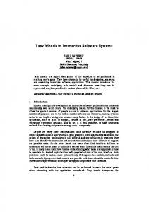
of interactive tasks are displayed. On the right-hand side of Figure 20 the panel “Set of User Services” displays the set of user services in the ICO specification that has been loaded. Here again it is possible to load several ICOs. The set of user services of each ICO appears in a separate tab widget. The lower part of the window in Figure 20 lists the set of associations that have been created when all the user services loaded in the ICOs have been associated with all the interactive tasks loaded in the “Task Tree” panel. Then, the “Launch Scenario Player” button is available. Clicking on this button opens the window presented in Figure 21 corresponding to the scenario player. This tool allows for loading a scenario (produced using CTTE tool presented in Figure 4) and executing it in PetShop. The scenario can thus be used to replace user interactions that would normally drive the execution of the ICO specification.
Fig. 21. The scenario player
The left-hand side of Figure 21 presents the set of actions in the selected scenario. The first line in the scenario represents the current task in the scenario. In Figure 21 the current task is “Select a plane” and is a user tasks i.e. the task is performed entirely by the user without interacting with the system. Clicking on the “Perform Task” button triggers the task and next task in the scenario becomes the current task. Figure 22 shows the scenario player in use. The righthand side of the figure shows the execution of the ICOs specification with the two main components: the Air Traffic Control application with the radar screen and the ATC simulator allowing for test purpose to add planes in the sector. Some tasks of interactive or application category require runtime information to be performed. For instance this is the case of interactive task “Click plane” that corresponds to the user’s action of clicking on a plane. Of course the click can only occur on one of the “current” planes in the sector and thus, the identification
110
D. Navarre et al.
Fig. 22. Execution of the scenario of the system
number cannot be known at design time and thus cannot be represented in the task model.
Fig. 23. Interaction between scenario and current execution: planes IDs are selected at runtime
Figure 23 provides an example of this aspect. Triggering the action “Click plane” in the task model requires a parameter i.e. a plane identifier. As this interactive task has been related to the user service “userAssume” (in the correspondence editor) the triggering of this task starts off the corresponding user service. However, the triggering of this service requires one of the values in the input place of the transition userAssume in the ObCS of the class MefistoPlaneManager (see Figure 7) i.e. one of the objects planes in the place Planes. In order to provide those values to the scenario player the set of all the objects in
A Tool Suite for Integrating Task and System Models through Scenarios
111
the place Planes is displayed on the right-hand side of the scenario player (see Figure 23).
Fig. 24. Interaction between scenario and current execution: values for frequency are selected at runtime
Figure 24 shows the same interaction occurring while selecting a value for the frequency. The set of frequencies in the place Frequencies (see Figure 15) is displayed for user’s selection in the scenario player. The tool shows a dialogue window when the scenario has been successfully played on the description of the application using the ICO formalism. A scenario fails when at some point no action can be performed and the list of actions still to be performed is not empty.
6
Conclusions
This paper has presented work that has been done in order to bridge the gap between task modelling and system modelling. The bridge is created by means of scenarios, which are considered here as sequences of tasks mapped onto sequences of actions in the system model. The use of scenarios is common practise in the design of interactive applications. We can thus obtain a design cycle that is thoroughly supported by dedicated software tools. The environment proposed for both task modelling and scenarios generation supports the editing of cooperative tasks, while that for editing and executing the formal description of system models supports distributed execution of models according to the CORBA standard. On the system modelling side, further work is currently under way in order to ease the editing of the presentation part of
112
D. Navarre et al.
the ICO models. Indeed, currently both activation and rendering functions are edited in a textual way, while graphical editing through direct manipulation would make this task easier. Future work will be dedicated to defining formal mappings between the two notations. Acknowledgements. The work presented in this paper has been partly funded by ESPRIT Reactive LTR project #24963, MEFISTO and by FT R&D (formerly CNET), the Research Centre of France Telecom, under the SERPICO project, grant number 98 1B 059.
References 1. Bastide, R´emi, and Palanque, Philippe. “Petri Net Objects for the Design, Validation and Prototyping of User-Driver Interfaces.” In 3rd IFIP Conference on Human-Computer Interaction, Interact’90, Cambridge, UK, Aug. 1990, 625-31. North-Holland, 1990. 2. Baumeister L., John B. and Byrne M. “A Comparison of Tools for Building GOMS Models.” In Proceedings CHI’2000, ACM Press, 2000. 3. Biere, M., Bomsdorf, B., Szwillus G. “Specification and Simulation of Task Models with VTMB.” In Proceedings CHI’99, Extended Abstracts, pp.1-2, 1999. 4. Bodart F., A-M. Hennebert, Leheureux J-M., I. Provot, and J. Vanderdonckt. “A Model-Based Approach to Presentation: A Continuum From Task Analysis to Prototype.” In 1st. EUROGRAPHICS Workshop on Design Specification and Verification of Interactive System (DSV-IS’94), Bocca di Magra, Italy, 8-10 June 1994. 5. Carroll, John (ed.). “Scenario-based Design.” John Wiley and Sons, 1995. 6. Navarre, D., Palanque, P., Bastide, R., Sy, O. “Specification of Middles Touch Screen using Interactive Cooperative Objects.” In Working Paper 2.5, MEFISTO Project: http://giove.cnuce.cnr.it/mefisto/wp2-5.html, (2000) 7. Object Management Group. “The Common Object Request Broker: Architecture and Specification.” CORBA IIOP 2.2 /98-02-01, Framingham, MA (1998). 8. Palanque, P., Patern` o, F., Bastide, R. and Mezzanotte, M. “Towards an Integrated Proposal for Interactive Systems design based on TLIM and MICO.” In Proceedings of DSV-IS’96, Springer Verlag 1996. 9. Palanque, Philippe, R´emi Bastide, and Fabio Patern` o. “Formal Specification As a Tool for the Objective Assessment of Safety Critical Interactive Systems.” In Interact’97, 6th IFIP TC13 Conference on Human-Computer Interaction, Sydney, Australia, 14 July 1997-18 July 1997, 323-30. Chapman et Hall, 1997. 10. Palanque, Philippe, R´emi Bastide, and Val´erie Seng`es. “Validating Interactive System Design Through the Verification of Formal Task and System Models.” In 6th IFIP Conference on Engineering for Human-Computer Interaction, EHCI’95, Garn Targhee Resort, Wyoming, USA, August 14-18. Chapman et Hall, 1995. 11. Palanque, Philippe, and R´emi Bastide. “Synergistic Modelling of Tasks, Users and Systems Using Formal Specification Techniques.” In Interacting With Computers 9, no. 2, 129-53, 1997. 12. Patern` o, F. “Model-Based Design and Evaluation of Interactive Application.” Springer Verlag, ISBN 1-85233-155-0, 1999.
A Tool Suite for Integrating Task and System Models through Scenarios
113
13. Patern` o, F. “The specification of the ConcurTaskTrees notation.” GUITARE Working Paper, March 2000. 14. Patern` o, F., Santoro, C., Sabbatino, V. “Using Information in Task Models to Support Design of Interactive Safety-Critical Applications.” In Proceedings AVI’2000, pp.120-127, ACM Press, May 2000, Palermo, 2000. 15. Patern` o, F., Mori, G., Galimberti, R. “CTTE: An Environment for Analysis and Development of Task Models of Cooperative Applications.” In Proceedings ACM CHI’01, Vol.2, ACM Press, Seattle, 2001. 16. Puerta, A.R., Eisenstein, J. “Towards a General Computational Framework for Model-Based Interface Development Systems.” In IUI99: International Conference on Intelligent User Interfaces, pp.171-178, ACM Press, January 1999. 17. Sy, Ousmane, Bastide, R´emi, Palanque, Philippe, Le, Duc-Hoa, Navarre, David. “PetShop: a CASE Tool for the Petri Net Based Specification and Prototyping of CORBA Systems.” In 20th International Conference on Applications and Theory of Petri Nets, ICATPN’99, Williamsburg, VA, USA. 1999. 18. van Welie M., van der Veer G.C., Eli¨ens A. “An Ontology for Task World Models.” In Proceedings DSV-IS’98, pp.57-70, Springer Verlag, 1998. 19. Wilson, S., Johnson, P., Kelly, C., Cunningham, J., and Markopoulos, P. “Beyond Hacking: a Model Based Approach to User Interface Design.” In HCI’93, Loughborough, U.K., 217-31. Cambridge University Press, 1993.