generally accepted development methodologies for virtual environments. Therefore, even ...... tools for the production of desktop software. Clearly, the goal of ...
A toolset supported approach for designing and testing virtual environment interaction techniques James S. Willans and Michael D. Harrison
Human-Computer Interaction Group Department of Computer Science, University of York Heslington, York YO10 5DD, U.K. e-mail: James.Willans,Michael.Harrison @cs.york.ac.uk �
Abstract Usability problems associated with virtual environments are a serious obstacle to their successful development. One source of these problems is that virtual environment toolkits provide only a small number of predefined interaction techniques that are expected to be used regardless of context, hence developers are not encouraged to consider interaction. In addition, there are no generally accepted development methodologies for virtual environments. Therefore, even when developers do consider interaction, it is likely to be in an ad-hoc unsystematic fashion driven by technology rather than requirements. If virtual environments are to be useful in a wider context, it is important to provide developers with methods (and tools to support the methods) by which interaction techniques can be systematically designed, tested and refined. In this paper we present the Marigold toolset which supports such a development process. The process begins with a visual specification of the technique being designed. This is requirements centred because it abstracts from implementation issues. Using the toolset, this specification is
1
refined to a prototype implementation so that the technique can be explored in the context of the other elements of the environment. In this way, the developer can verify the technique against requirements in both the specification and prototype. Additionally, because the specification is readily understandable, users can be involved at both stages of the process.
1 Introduction Despite their great potential, highly interactive virtual environments remain poorly represented outside specialised laboratories [Derra 1995]. One reason is that the cost of buying the specialised equipment, such as headsets and datagloves, remains high (although this has been significantly reduced in recent years). However, analysis has also shown that the usability of virtual environments tends to be poor [Kaur, Maiden, and Sutcliffe 1996]. This is particularly the case with interaction techniques. An interaction technique defines a consistent mapping between the user and the virtual environment technology, and how the environment will react as a user interacts with the input devices. An anology can be drawn between virtual environment interaction techniques and those found on desktop interfaces such as ‘point and click’. Even virtual environments which contain moderately complex interaction techniques suffer problems [Bowman and Hodges 1995]: ‘More complex systems remain in research laboratories, because while functionality is impressive, their interface to that functionality and their user interaction metaphors, are inconsistent, imprecise, inefficient, and perhaps unusable.’ These problems are not simply solved by more realistic modelling of real world techniques. The environment may not be analogous to a real world situation. Indeed, one of the main advantages of virtual environments is that the user can perform tasks not physically possible in the real world such as flying round the design of a proposed product [Thompson, Maxfield, and Dew 1999] or in the novel visualisation of complex data [Sastry, Boyd, Fowler, and Sastry 1998]. Even when there is a real world equivalent, usability reports have shown that techniques ‘closer to natural mapping often exhibit serious usability problems’ [Bowman 1999]. We believe that the diversity of virtual environments dictates that in most cases an interaction technique will only be effective if it has been designed (or selected) for the requirements of the environment and in conjunction with users. An interaction technique which is highly usable in one 2
context is likely to be less usable within another. This view is supported by the development of new interaction techniques for specific environments [Hand 1997; Mine 1995; Mackinlay, Card, and Robertson 1990; Ware and Osborne 1990]. Developers must, then, consider the requirements of the individual environments and build new techniques or re-mould previous techniques in view of the requirements. In practice, popular toolkits such as Superscape [Corporation 1999] and dVise [duPont 1995] do not encourage developers to consider interaction. They provide a small number of predefined interaction techniques (bound to physical devices) which are expected to be used regardless of the context. The focus within the toolkit community has been on the technological aspects of virtual environments such as distributing the computational load inherent in such systems (for instance the Metis toolkit [Turner, Li, and Gobbetti 1999]). Secondly, there are no defined development methodologies for virtual environments akin to those found in the other disciplines of software engineering, particularly research has shown that developers ‘rarely test with users’ [Kaur, Maiden, and Sutcliffe 1996]. Therefore, even when interaction is considered, it is in an ad-hoc unsystematic fashion driven by technology rather than requirements. Given this situation, it is hardly surprising that users experience interaction problems. As noted by Stanney ‘if humans cannot perform effectively within virtual environments, then further pursuit of this technology may be fruitless’ [Stanney 1995]. If virtual environments are to be useful in a wider context, it is important to provide developers with methods (and tools to support the methods) by which interaction techniques can be systematically designed, evaluated and refined. In this paper we begin by examining a toolkit supported approach which has been successful for the interaction design of other classes of system. In section 3 we discuss the issues associated with applying a similar approach to virtual environments. Taking into account these issues, section 4 introduces the Marigold toolset which supports such an approach for virtual environments. In section 5 we illustrate the usage of the new approach. In section 6 we discuss related work. Finally, in section 7 we summarise our conclusions.
2 Interaction design Interaction problems are not unique to virtual environments: almost every form of non-trivial interactive system suffers to some extent. One process which has proved useful in the design of some
3
interactive systems (e.g direct manipulation interfaces) is that supported by Statemate [Harel, Lachover, Naaad, Pnueli, Politi, Sherman, Shtull-Trauring, and Trakhtenbrot 1990]. Statemate was developed to aid in the design and prototyping of the behaviour of dynamic systems (systems whose state changes autonomously over time). This tool has been used in industry especially for the design of safety critical systems. Statemate utilises statecharts [Harel 1987] for the specification of the behaviour. This formalism describes the behavioural ordering of the system (what can happen and in what sequence) but does not formally describe the meaning of the states. Visual renderings can then be added to the specification so that the behaviour can be explored interactively as a prototype. In the context of interactive systems, the Statechart specification can be considered an interaction specification. The advantages of this approach are numerous. Because the specification abstracts from implementation issues, it is requirement-centered �
rather than implementation-centered. As a consequence, the design is driven by what the user requires rather than specific implementation abstractions. This is clearly advantageous in terms of usability. The visual nature of the specification makes it more acceptable to users as well as developers �
and the consequences of interactions can be explored by users within the specification. This presents the opportunity for users to be involved within the design process (at an early stage) and influence the resulting system. The presence of desirable usability properties can be proved within the specification. This is �
difficult to achieve in the implementation code because the behaviour is often embedded within the other elements that compose the system. An ability to refine specifications means that the behaviour can also be explored within the �
context of the other elements of the environment (i.e. the visual renderings). �
The specification acts as an accurate documentation of the system it is specifying. Such documentation is essential to any non-trivial software engineering project [Sommerville 1996].
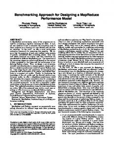
The design process supported by Statemate is visualised in figure 1. The requirements are used to design an interaction model (specification) which can then be verified, either informally or formally, against the requirements. The results of this process are used to refine the interaction model so that it
4
Requirements
Verify model
Interaction model
(formally/informally)
Refine model
Verify prototype
Interaction prototype
(Informally)
Figure 1: The design process supported by Statemate (the broken lines indicates where information is used from earlier stages of the process) [process.gif]
more accurately reflects the requirements. From the interaction model a prototype may be generated which can be used to test the interaction design with users and ensure it meets their requirements. The model is also refined according to the results of this process. Clearly, the ability to apply such an approach to the design of virtual environment interaction is desirable: it would provide developers with a means of designing, testing and refining interaction techniques in a manner which involves the user. However, there are additional issues in virtual environments which make the application of the Statemate tool unsuitable.
3 Virtual environments issues There are three major issues which pertain to the application of the Statemate tool as an aid to designing virtual environment interaction techniques. The first issue relates to modelling the behaviour of interaction techniques; for this a number of formalisms have been investigated. In [Smith, Duke, Marsh, Harrison, and Wright 1998; Smith and Duke 1999a] purely state based approaches were dismissed because they fail to capture the interesting and distinguishing features of interaction techniques. For instance, figure 2 shows a state machine
5
Stationary
Moving
Figure 2: A purely state description of an interaction technique stateMachine.gif
which can describe many interaction techniques. It is unclear from this description how the state is changed from stationary to moving or whether, for instance, the process that caused the initial state change to moving is also the process which changes the state back to stationary. Moreover, it is ambigious how these states relate to the physical state of the interaction devices. A more precise description requires additional abstractions to enable the developer to describe these important details. Smith et al. concluded that a more suitable formalism would be a hybrid of discrete state and continuous data-flow behaviour. The additional continuous constructs provide a means of describing the processes that occur during a discrete state. A similar conclusion has also been reached indepedently by Jacob [Jacob 1995]. This insight means that because statecharts do not model continuous dataflow behaviour, they are not ideal for modelling classes of interaction techniques required for virtual environments. Rather, a new formalism must be chosen which better captures the hybrid nature of virtual environment behaviour. The second issue relates to how the specification is refined to a prototype. Within Statemate the statechart specification maps onto a predefined set of visual renderings. This is adequate for testing the behaviour of those systems which conform to a common interface (i.e. switches, sliders and dials). However, because of the diversity of virtual environments, we cannot reuse visual renderings in this way. The renderings must be specific to each individual environment. The third issue relates to how the virtual environment prototype is tested. There are two aspects of the interaction technique that need to be verified. Firstly, its capability - what can be done or not done using the interaction technique. Secondly, its usability - how easily can the capability of the interaction technique be utilised by the user. This distinction closely corresponds to that discussed by Buxton [Buxton 1986]. A convenient way of viewing this relation between input devices and interaction techniques is by measures and triggers [Duce, van Liere, and ten Hagen 1990]. A measure
6
Interaction devices
Measures and triggers
Interaction techniques
capability usability
Figure 3: The relation between virtual environment input devices and interaction techniques [deviceTechnique.gif]
is the type and value to be passed between the physical device and the interaction technique e.g. the position of a three-dimensional tracking device. A trigger is a discrete event to be passed between the physical device and the interaction technique e.g. a button click. An interaction technique’s capability can be determined from its trigger and measures interface without any knowledge of the input device(s). However, the usability of an interaction technique, is determined by the physical input device(s). For example, a 3D mouse and a Polhemus magnetic tracker both have six degrees of freedom and can be substituted within a technique requiring such a measure and trigger interface. Substituting the device in this way does not alter the capability of the technique, but does alter the usability. Using the Statemate tool, the user interacts with the specification (manipulates the visual renderings) using the mouse. The emphasis within this form of prototype is to check the specification interactively for undesirable consequences such as state deadlock. Hence, Statemate supports the testing of the capability of the specification but not the usability. In order to test the usability of the specification, the device interface to the user must match that of the intended context. Therefore, the refinement to a prototype must allow easy experimentation with different device-technique configurations so that both the capability and the usability of the technique can be evaluated. This distinction is visualised in figure 3.
4 The Marigold toolset In this section we introduce the Marigold toolset which, taking into account the issues raised in the previous section, supports the design, testing and refinement of virtual environment interaction techniques in a style similar to Statemate. Marigold consists of two tools. The hybrid specification builder
7
Marigold toolset
Interaction Specification
Hybrid Specification Builder
Virtual environment implementation
Prototype Builder
Other elements of the VE (I/O)
MAVERIK VE toolkit
Figure 4: The process supported by the Marigold toolset [processOverview.gif]
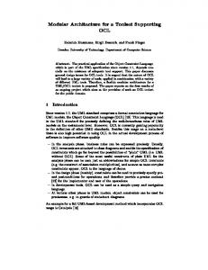
(HSB) provides a means of specifying interaction techniques independent of the virtual environment. From the HSB a stub of the interaction technique is generated. This is a context independent description of the technique. The prototype builder (PB) then provides a means of integrating the interaction technique stub into the other elements of the virtual environment (e.g., the devices and visual renderings). From this a virtual environment implementation is generated. The current version of the tool generates C code using the Maverik virtual environment library [Hubbold, Dongbo, and Gibson 1996] 1 . Both tools use visual specification thus making comprehension more effective. An overview of this process is illustrated in figure 4.
4.1 The specification formalism A commitment to a formalism was an initial design decision in the development of the Marigold toolset. We decided to use the Flownet hybrid specification formalism presented in [Smith and Duke 1999b; Smith, Duke, and Massink 1999] which was developed specifically for the specification of virtual environment interaction techniques. The notation utilises Petri-nets [Petri 1962] to describe the discrete behaviour (standard place transition nets with the added construct of an inhibitor arc) and elements of a systems dynamics modelling notation [Forrester 1961] to describe the continuous 1 Although the target implementation is currently Maverik, the Marigold process is toolkit independent and could be, in principle, used with other toolkits
8
data-flow behaviour. There are a number of reasons we chose Flownets. Firstly, like Statecharts, the formalism is not concerned with the low level (implementation) detail of the states, only behavioural ordering. Although the lower level detail can add important characteristics to a technique (a full characterisation of any artifact is its complete implementation), it reduces complexity to address such concerns separately as a refinement rather than at the same level of abstraction. This reduction in complexity allows clearer thinking about the requirements and how they can be achieved within the design. Secondly, Flownets has a strong notion of the interface between the system and the user through the data-flow constructs (although it does not describe the low level detail of the data). Finally, the specifications are compact, readable and have a relatively small number of constructs. Another possible choice of formalism, which has been considered as a method for describing virtual environment interaction techniques in [Massink, Duke, and Smith 1999], is HyNet [Wieting 1996] also based around the Petri-net notation. However for our purposes, this formalism suffers from two main problems. Firstly, even for simple interaction techniques, the specification becomes large and difficult to read. This is because HyNet tries to capture an exhaustive description of the hybrid system at one level of abstraction: the state behaviour, the data structure and the transformation of the data (a great deal of information is also captured in text which augments its complexity). Secondly, it is not obvious from the specification what the relation between the system and the user is. This makes comprehension and analysis of the human-computer dialogue difficult. These problems are clearly illustrated by the example in [Massink, Duke, and Smith 1999]. Jacob et al. have developed another visual hybrid formalism which describes virtual environment interaction [Jacob 1996; Morrison and Jacob 1998]. Again, because this was designed as a control formalism for a virtual environment user interface management system (UIMS), as part of a design process we consider it to be a mix of abstractions. Although this formalism results in more compact specifications than Hynet, the use of two separated notations for the discrete and continuous parts of the specification makes comprehension difficult. Appendix A contains a list and description of the components used within Flownets (taken from [Smith and Duke 1999b]). We will explain the formalism by means of an example. The mouse based flying interaction technique enables flying through a virtual environment using the desktop mouse. Variations of it are used in many desktop virtual environment packages (e.g. the virtual production planner). One variation works as follows. Flying is initiated by pressing the middle mouse button and moving the mouse away from the clicked position. The user’s speed and direction is directly 9
proportional to the angle and distance between the current pointer position and the location at which the middle mouse button was pressed. Flying is deactivated by a second press of the middle mouse button. The technique (shown in 5) has one input: mouse, and one output: position. When the middle mouse button is pressed, the Flownet middle mouse button sensor is activated and the start transition (1) is fired. The start transition enables the continuous flow which updates origin with the current mouse position (2). A token is then placed in the idle state. When the out origin sensor detects that the mouse has moved away from the origin position, transition (3) is triggered and the token is moved from the idle to the flying state. A token in the flying state enables the continuous flow which calculates the translation on position (4) using the current mouse position and the origin. This is then continuously supplied to the output plug. Whenever the flying state is enabled, the inhibitor implies that the start transition cannot be re-fired. When the in origin sensor detects that the mouse has moved back into the origin position, the token in the flying state is returned to the idle state closing the flow control and halting the transformation of position. Regardless of whether the technique is in the idle or flying state, the technique can be exited by the middle mouse button sensor becoming true and firing one of the exit transitions (5 or 6).
4.2 Building the specification using Marigold HSB The hybrid specification builder (HSB) provides a means of visually specifying interaction techniques using the Flownets specification formalism discussed in the previous section. The resulting specification for the mouse based flying technique is illustrated in figure 6. The toolbar at the top of the diagram contains an option for each of the node types (e.g., state, transition and transformer) and each of the connection types (e.g., continuous and discrete). The HSB enforces the static semantics of the specification and only allows legal connections between nodes. The tool also tries to maintain clarity of specification by automatically formatting the visual connections between components. There are two stages to the refinement of an interaction technique specification towards an implementation prototype. The first stage takes place in the HSB. This involves adding a small amount of code to some of the nodes within the specification. There are three types of code that can be added. We will describe these in the context of the mouse based flying example: 1. variable code - this is placed in the plugs of the specification (plugs are input/output to the
10
mouse
position
�
2
update origin
~
�
out origin �
in origin
update position
�
~
�
origin
position
�
1 �
�
middle mouse button
4
�
3
�
start
flying
�
idle
�
exit �
exit �
5 �
6 �
Figure 5: The mouse based flying interaction technique [need gif]
Figure 6: Mouse based flying Flownet specification in Marigold HSB [mbfHybr]
11
environment outside the technique). It describes what kind of information flows in and out of the plugs and, hence, around the specification. Illustrated in figure 7 (a) is the code added to the mouse plug. An integer variable representing the state of the mouse buttons and a vector representing the mouse position. Variable code is also used to define data which reside in the stores. 2. conditional code - this is placed in some transitions and all sensors. It describes the threshold state of the data for firing the component. Illustrated in figure 7 (b) is the code added to the middle m/but sensor. As can be seen from figure 7 (b), the HSB informs the developer which data flows in and out of the node (i.e. which data they are able to access). The code specifies that when the middle mouse button is pressed, the sensor should fire. 3. process code - this is placed in all transformers and denotes how the information flowing into the transformer is transformed when enabled. Illustrated in figure 7 (c) is the code added to the position transformer. This describes how position should be transformed using the current mouse position and the origin position. Once the code has been added, it is necessary to generate a stub of the interaction technique. The interaction technique specification, along with all the information added to the nodes, can also be saved to a file and loaded back into the Marigold HSB for later refinement. The second stage of the specification to prototype refinement involves integrating the interaction technique specification into an environment (e.g. input devices, output devices and world objects). This is done within the prototype builder (PB) and will be explained in the next section.
4.3 Constructing a prototype using Marigold PB The hybrid specification is an environment independent description of the interaction technique. By this, we mean that it does not make commitments to the inputs and outputs from the technique. In order to explore the technique in an implementation prototype context, it is necessary to ‘plug’ it in to an environment. This stage of the refinement is supported by the Marigold prototype builder (PB). We have found it convenient to model a virtual environment as five concepts: interaction techniques, interaction devices, viewpoints, world-objects and cursor objects. We will briefly define these concepts in the context of the PB:
12
Figure 7: a) Adding variables to the mouse input plug b) Adding conditional code to the middle mouse button sensor c) Adding process code to the position transformer [mbfCode.gif]
Definition 1 Interaction techniques define a consistent mapping of the interaction devices onto the other components of the virtual environment. Definition 2 Interaction devices are physical devices which act as an input to interaction techniques. Definition 3 Viewpoints visually render a subset of world objects and cursor objects to the user. They have an initial state (position) which may be altered by an interaction technique during interaction. Definition 4 World objects are objects which exist within the virtual environment. They have an initial state (position) which may be altered by an interaction technique during interaction. These may also represent the user, or part of the user, visually within the environment (often referred to as an avatar). Definition 5 Cursor objects are objects which do not exist in the environment, but are rendered within the environment viewpoint(s) to give an indication to the user of the interaction device’s state (i.e. positional feedback). Marigold PB provides a visual method of connecting these elements as inputs and outputs to one or more interaction technique2. Illustrated in figure 8 is the mouse based flying interaction technique 2 More
than one interaction technique may be concurrently active.
13
Figure 8: Complete implementation specification for a virtual environment using the mouse based flying interaction technique [mbfPb.gif]
within the PB and connected into an environment. The toolbar at the top of the diagram contains an option for each of the elements described above and the interaction technique itself. In order to construct a prototype it is necessary to select these options and click on the workspace to insert an object instance. As can be seen from figure 8 each node has a set of variables and the variables for the mouse based flying interaction technique (mbf) are those that were placed in the plugs within the HSB. What cannot be seen, from this black and white figure, is that each variable has a different background colour denoting whether it is an input, output or both. The relation between the environment elements are defined by joining these variables. Essentially the joining of two variables is defining a data flow from one to another. The tool automatically verifies that the variables being joined are of the correct type and are semantically correct. Within the mouse based flying specification, we have linked a desktop mouse, as an input to the technique, and a viewpoint, as an output from the technique. Additionally, we have inserted an office desk world object so that the movement of the viewpoint can be perceived. However because the desk remains static during interaction, it is not linked to any other element of the environment. When a
14
Figure 9: Setting the initial state of the office desk world object [mbfPbEditOb.gif]
world object is inserted it is necessary to specify the file location of the object’s image3 . In the case of an input device, the location of a device stub is required. These device stubs are short textual files which can be constructed easily by the developer. They relate the output of each device to a common data layer of measures and triggers (in a manner similar to that presented in [Faisstnauer, Schmalstieg, and Szalav´ari 1997]) allowing devices to be easily substituted within interaction techniques. It is necessary to define the initial state of the viewpoint and world object elements. Illustrated in figure 9 is the dialogue box for setting the state of the office desk world object. Once the specification is complete the code for the environment can be automatically generated and compiled.
5 Discussion In the previous section we presented the Marigold toolset which supports a Statemate-like process for virtual environments. The advantages of the Statemate approach were discussed in section 2; in this section we will briefly examine some of these benefits in the context of Marigold. We will exemplify 3 this
would be generated from a 3D-modeller such as 3DStudio
15
these by using the two handed flying interaction technique as an example. Two handed flying, detailed in [Mine, Brook Jr, and Sequin 1997], enables flying through a virtual environment in a direction determined by the vector between the user’s two hands and at a speed relative to their hand separation. Movement can be halted when the user’s hands are brought together. The Flownet specification of this interaction technique is shown in figure 10 inside the Marigold HSB. There are three plug inputs: enable, disable and hand position (pictorially duplicated for clearness of specification), and one output plug: position. The technique is enabled by the firing of the start transition, upon which a token is placed in the not flying state. When the distance between the user’s hand positions exceeds the minimum distance the d min sensor triggers true the associated �
transition moves the token from the not flying state to the flying state. When the distance between the users’ hand position is less than or equal to the minimum distance, the d =min sensor triggers �
true and the associated transition moves the token from the flying state back to the not flying state. Regardless of whether the user is in the flying or not flying state, the technique can be exited by the firing of one of the exit transitions. When there is a token in the flying state the flow control is enabled and the position store is transformed using information from the speed and direction stores (which, because of the absence of flow controls, are continuously transformed regardless of the state of the Petri-net). The transformation on position is continuously output to the plug.
5.1 Specification As mentioned in section 2, one of the virtues of starting a design with a specification is that it can abstract from implementation issues. This is additionally true of the Flownet specification used by Marigold. The specification at this level is not concerned with precisely what data flows around the specification or how this data gets manipulated by the states. Therefore, the technique can be considered and designed in a requirements, or user, centred manner. This contrasts with the alternative method of designing interaction techniques directly at code level where the implementation concerns must also be considered. With respect to the two handed flying example, details such as the calculations to transform position are left to the refinement as are defining the exact meaning of the start and exit transitions. In addition, using program code it is often difficult to separate an interaction technique from other elements of the environment (input and output devices, for instance) which makes the independent inspection of the interaction technique problematic.
16
Figure 10: Flownet specification of the two handed flying interaction technique in Marigold HSB [thfHybr.gif]
The Flownet description is essentially a description of the dialogue between the user and the interactive system. Within human-computer interaction such descriptions are often used to reason about the usability of the interface. For instance, one general principle is that an interactive system should accurately render its state to the user so that they do not suffer mode confusion [Degani 1996]. Mode confusion is where the user thinks the system is in on state when it is actually in another and can result in the user misunderstanding how the system will interpret their input. To illustrate how this mode confusion principle can be successfully checked for in the Flownet specification of a virtual environment interaction technique, consider once again the two handed flying technique. We can see from the specification in figure 10 that the technique renders some change into the environment when the flying state is enabled, however there is no such rendering when the technique is in the not flying state. This could very easily lead to mode confusion because the user is not able to perceive from the state of the environment whether or not the interaction technique is active when they are stationary. To overcome this problem a redesigned version of the interaction technique is shown in figure 12. This incorporates additional detail so that when it becomes active or inactive a notification is passed to the outside environment (via. the output to the thf plug). The re-wiring of the prototype is shown in
17
original THF revised THF
not active No No
not flying No Active
flying Moving Moving
Figure 11: A comparison of the feedback given to the user during execution of the two hand flying technique
figure 13, the notification from the technique is mapped onto the variable of a world object indicating visibility which displays active when this variable is true. The position of the active world object is also updated using the position output so that it always remains in the viewpoint. Hence, the active world object is initially set to invisible, when the technique is enabled it becomes visible and invisible when the technique is disabled. A comparison of the two versions of the techniques is shown in figure 11 and a screenshot of the revised technique in use is shown in figure 14.
5.2 Prototype As noted by Myers ‘the only reliable way to generate quality interfaces is to test prototypes with users and modify the design based on their comments’ [Myers 1989]. In section 3 we discussed the requirements of a virtual environment prototype which supports the verification of the capability and usability. Within this section we discuss exactly how Marigold, and the prototype generated from Marigold PB, supports such verification. The capability issues relate to whether the technique is physically able to support navigation in the manner required. For instance, in figure 13 the two handed flying technique stub was inserted into an environment which allows the exploration of a car exterior. The generated prototype, illustrated in figure 14 allows the developer to verify whether the capability of the technique supports this requirement. One surprising limitation of the capability of this technique, which was not apparent until we tested the prototype, was that it does not control the pitch, roll and yaw axis. Consequently, the user is always facing the same direction and cannot turn around. The device independent nature of the interaction technique specified within Marigold HSB provides the ability to test the capability of the technique using any device that matches the technique’s requirements in terms of triggers and measures (discussed in section 3). This is useful because the target environment for a virtual environment is often different from the host environment in which the system is developed. Therefore, devices that are available to the development environment (in
18
Figure 12: The amended Flownet specification which takes into account potential mode confusion [thf2Hybr.gif]
Figure 13: The amended two handed flying prototype specification [thf2Pb.gif]
19
our case a desktop workstation) can be used to verify the capabilities of the technique. Figure 13 shows a prototype specification using the two handed flying technique. The original description of this technique in [Mine, Brook Jr, and Sequin 1997] specifies that two 3D trackers (such as the Polhemus magnetic trackers) should be used to measure the user’s hand positions. As seen in figure 13, the keyboard was mapped onto the left hand and the mouse onto the right hand. These pseudo-devices were also mapped onto cursors so that their relative distance can be perceived in the viewpoint (this would not be necessary with Polhemus trackers because the user has a proprioceptive sense of the relative position of their hands). Additionally, a keyboard mapping was made to enable and disable the technique. The position output from the technique was mapped onto a viewpoint and a car world object was placed within the environment. In this way, the capability of a technique can be tested in the development environment. In section 3 we discussed the requirements of a prototype if the usability of the technique be determined, we concluded that it is necessary to test the technique with the intended input devices. Marigold PB supports easy reconfiguration of the relation between devices and techniques in this way, simply by re-wiring real device stubs into the interaction technique and re-generating the prototype code. With reference to the two handed flying technique, usability details that would be verified are whether the hand-distance to speed mapping was such that control could be maintained as the user navigated around the car. Such ease of reconfiguration also provides a useful method for exploring the usability of alternative device-technique configurations.
6 Related work In [Bowman 1999] a method is present for designing interaction techniques. The main motivation behind this work is to provide a method for selecting interaction techniques for a specific task and a framework is presented which supports this process. The framework results in a high level description of the components constituting the required interaction techniques. Our work presented in this paper complements this process. It is able to refine these high level descriptions of the required techniques to specification where usability factors such as moding can be verified. An approach to designing complete virtual environments is introduced in [Kim, Kang, Kim, and Lee 1998] which contains a component for describing the dynamic behaviour of the system using Statecharts. As justified earlier in this paper, interesting features of virtual environment interaction
20
Figure 14: The amended two handed flying prototype as generated from Marigold PB need gif
techniques are captured in the hybrid behaviour which are not necessarily captured in Statecharts. Consequently, the dynamic specification can be abstract, awkward and fail to show important details of the technique. However, the focus of this work is non-user driven virtual environments for production line prototyping. As a consequence, the behaviour of these systems is pre-defined and not dynamic in the manner of the interaction techniques discussed in this paper. In section 4.1 we discussed the hybrid notation developed by Jacob et al. and presented in [Jacob 1996; Morrison and Jacob 1998] for use in a UIMS. Similarly, the work we present here links a hybrid specification to implementation but in a different way. Our starting point is a high level specification which is then refined to a prototype. Jacob’s work already has an implementation as a starting point, this is then linked to the higher level notation so that changes made in the specification are propagated to the implementation (in the traditional UIMS manner). Another approach which provides a method for building interaction techniques visually is presented in [Steed 1996]. The motivation behind this work is to provide the ability to specify the behaviour of the virtual environment while immersed in the environment to provide an easy transition between construction and testing. The visual notation provides a very high level set of components which are plugged together to specify the interaction. The visual notation includes logical/boolean gates such as not and and and is very similar to the approaches taken by early visual programming tools for the production of desktop software. Clearly, the goal of this work is to show that interaction
21
can be defined immersively. However, the high level, completely visual, language severely limits what can be achieved. Additionally, the visual specification is not particularly useful for analysis (moding is not shown, for instance).
7 Conclusions In this paper, we have motivated a need for a systematic method of designing, testing and refining virtual environment interaction techniques. We have discussed why the process supported by the Statemate tool is desirable, but examined issues which make the direct application of this tool unsuitable. The Marigold toolset has been introduced which supports a similar process to Statemate but with the additional consideration of issues which pertain to modelling and verifying virtual environment interaction techniques. We have discussed and demonstrated with an example the usefulness of the presented approach. Currently we are in the process of designing extensions to the tool to support selection and manipulation based interaction techniques. Additionally, we are exploring the design benefits of the prototype builder [Willans and Harrison 2000a], how well the Marigold process can be applied to defining the behaviour of world objects [Willans, Harrison, and Smith 2000] and the automated formal verification of the hybrid specifications [Willans and Harrison 2000b].
Acknowledgements We are grateful to Jon Cook at the Advanced Interface Group at the University of Manchester for his help with the details of Maverik. We are also grateful to Shamus Smith and David Duke for their comments. Finally, we would like to thank the reviewers who provided useful feedback on early versions of this paper.
22
References Bowman, D. A. (1999). Interaction Techniques for Common Tasks in Immersive Virtual Environments - Design, Evaluation and Application. Ph. D. thesis, Georgia Institute of Technology, USA. Bowman, D. A. and L. F. Hodges (1995). User interface constraints for immersive virtual environment applications. Technical Report TR95-26, Graphics, Visualisation and Usability Center, Georgia Institue of Technology. Buxton, W. (1986). There’s more to interaction than meets the eye: Some issues in manual input. In D. A. Norman and S. W. Draper (Eds.), User Centered System Design, Chapter 15, pp. 319–337. Lawrence Erlbaum Associates. Corporation, S. (1999). Superscape. 3945 Freedom Circle, Suite 1050, Santa Clara, CA 95054, USA. Degani, A. (1996). On Modes, Error, and Patterns of Interaction. Ph. D. thesis, Georgia Institue of Technology, USA. Derra, S. (1995). Virtual reality: Development tool or research toy? Research and development Magazine 5(1), 146–158. Duce, D. A., R. van Liere, and P. J. W. ten Hagen (1990). An approach to hierarchical input devices. Computer Graphics Forum 9(4), 15–26. duPont, P. (1995). Building complex virtual worlds without programming. In R. C. Veltkamp (Ed.), Eurographics’95 STAR report, pp. 61–70. Eurographics. Faisstnauer, C., D. Schmalstieg, and Z. Szalav´ari (1997, August). Device-independent navigation and interaction in virtual environments. Technical Report TR-186-2-97-15, Vienna University of Technology, Austria. Forrester, J. W. (1961). Industrial Dynamics. MIT Press. Hand, C. (1997). A survey of 3D interaction techniques. Computer Graphics Forum 16(5), 269– 281. Harel, D. (1987). Statecharts: A visual formalism for complex systems. Science of Computer Programming 8, 231–274.
23
Harel, D., H. Lachover, A. Naaad, A. Pnueli, M. Politi, R. Sherman, A. Shtull-Trauring, and M. Trakhtenbrot (1990, July). STATEMATE: A working environment for the development of complex reactive systems. IEEE Transactions on Software Engineering 16(4), 403–413. Hubbold, R. J., X. Dongbo, and S. Gibson (1996). MAVERIK - the Manchester virtual environment interface kernel. In M. Goebel and J. David (Eds.), Proceedings of 3rd Eurographics Workshop on Virtual Environments. SpringerVerlag. Jacob, R. J. K. (1995). Specifying non-WIMP interfaces. In CHI’95 Workshop on the Formal Specification of User Interfaces Position Papers. Jacob, R. J. K. (1996). A visual language for non-WIMP user interfaces. In Proceedings IEEE Symposium on Visual Languages, pp. 231–238. IEEE Computer Science Press. Kaur, K., N. Maiden, and A. Sutcliffe (1996). Design practice and usability problems with virtual environments. In Proceedings of Virtual Reality World ’96. Kim, G. J., K. C. Kang, H. Kim, and J. Lee (1998). Software engineering of virtual worlds. In ACM Virtual Reality Systems and Technology Conference (VRST’98), pp. 131–138. Mackinlay, J. D., S. K. Card, and G. G. Robertson (1990, August). Rapid controlled movement through a virtual 3D workspace. Computer Graphics 24(4), 171–176. Massink, M., D. Duke, and S. Smith (1999). Towards hybrid interface specification for virtual environments. In Design, Specification and Verification of Interactive Systems ’99, pp. 30–51. Springer. Mine, M. R. (1995). Virtual environment interaction techniques. Technical Report TR95-018, UNC Chapel Hill Computer Science, USA. Mine, M. R., F. P. Brook Jr, and C. H. Sequin (1997). Moving objects in space: Exploiting proprioception in virtual-environment interaction. In SIGGRAPH 97, pp. 19–26. ACM SIGGRAPH. Morrison, S. A. and R. J. K. Jacob (1998). A specification paradigm for design and implementation of non-WIMP human-computer interaction. In ACM CHI’98 Human Factors in Computing Systems Conference, pp. 357–358. Addison-Wesley/ACM Press. Myers, B. A. (1989). User-interface tools: Introduction and survey. IEEE Software 6(1), 15–23. Petri, C. A. (1962). Kommunikation mit automaten. Schriften des iim nr. 2, Institut f¨ur Instrumentelle Mathematic. English translation: Technical Report RADC-TR-65-377, Griffiths Air 24
Base, New York, Vol. 1, Suppl. 1, 1966. Sastry, L., D. R. S. Boyd, R. F. Fowler, and V. V. S. S. Sastry (1998). Numerical flow visualization using virtual reality techniques. In 8th International Symposium on Flow Visualisation, pp. 235.1–235.9. Smith, S. and D. Duke (1999a). Using CSP to specify interaction in virtual environments. Technical Report YCS 321, University of York - Department of Computer Science. Smith, S. and D. Duke (1999b). Virtual environments as hybrid systems. In Eurographics UK 17th Annual Conference, pp. 113–128. Eurographics. Smith, S., D. Duke, T. Marsh, M. Harrison, and P. Wright (1998). Modelling interaction in virtual environments. In UK-VRSIG’98. Smith, S., D. Duke, and M. Massink (1999). The hybrid world of virtual environments. Computer Graphics Forum 18(3), C297–C307. Sommerville, I. (1996). Software Engineering (Fifth ed.). Addison-Wesley. Stanney, K. (1995). Realizing the full potential of virtual reality: human factors issues that could stand in the way. In VRAIS’95 Conference, pp. 28–34. IEEE. Steed, A. J. (1996). Defining Interaction within Immersive Virtual Environments. Ph. D. thesis, Queen Mary and Westfield College, UK. Thompson, M. R., J. D. Maxfield, and P. M. Dew (1999). Interactive virtual prototyping. In Eurographics UK 16th Annual Conference, pp. 107–120. Eurographics. Turner, R., S. Li, and E. Gobbetti (1999). Metis - an object-orientated toolkit for constructing virtual reality applications. Computer Graphics Forum 18(2), 121–130. Ware, C. and S. Osborne (1990). Exploration and virtual camera control in virtual three dimensional environments. In Proceedings of Symposium on Interactive 3D Computer Graphics, pp. 175–183. ACM Press. Wieting, R. (1996). Hybrid high-level nets. In J. M. Charnes, D. J. Morrice, and D. T. Brunner (Eds.), Proceedings of the 1996 Winter Simulation Conference, pp. 848–855. ACM Press. Willans, J. S. and M. D. Harrison (2000a). A ‘plug and play’ approach to testing virtual environment interaction techniques. In 6th Eurographics Workshop on Virtual Environments, pp. 33–42. SpringerVerlag. 25
Willans, J. S. and M. D. Harrison (2000b). Verifying the behaviour of virtual environment world objects. In Workshop on design, specification and verification of interactive systems (in press). Lecture notes in computer science. Willans, J. S., M. D. Harrison, and S. P. Smith (2000). Implementing virtual environment object behaviour from a specification. In User Guidance in Virtual Environments, pp. 87–97. Shaker Verlag, Aachen, Germany.
26
Appendix A name state
symbol
description A discrete state, as used in Petri nets. Each state can hold one token, indicating whether or not the state is active. Inputs: control arcs from transitions. Outputs: control arcs to transitions or flow controls.
transition
A discrete transition. A transition can fire when all the control arcs leading to it are associated with states that contain a token, and/or sensors that are reading true. In addition, any inhibitor arcs must lead to states that are not active, or sensors which evaluate false. Inputs: control and inhibitor arcs from states and sensors. Outputs: control arcs to states.
control arc
A control arc signals a control dependency from one component to another, e.g. a transition can depend on a state or the value of a sensor. Arcs can start or end at states and transitions can start from sensors, and can end at flow controls.
inhibitor arc
An inhibitor behaves like a control arc, except that an enabling condition at the start of the arc acts as a disabling condition for whatever is attached at the end of the arc. For example, a transition with an inhibitor arc originating from a state cannot fire if the state is active.
flow control
A flow control straddles a continuous flow (passing through the symbol horizon tally as shown) and acts as a valve. Information or other resources can only pass if the control arc attached to the “waist” are enabled and any inhibitor disabled. Inputs: a continuous flow and one or more control/inhibitor arcs. Outputs: a continuous flow.
continuous flow
A continuous flow represents a flow of information that we wish to consider as continuous in some context, for example readings from some input device, or monitoring of some state. When a flow is spanned by a flow control, the “content” of the flow downstream from the control is only defined at times when the flow control is open.
sensor
A sensor spans a continuous flow, and acts as a function from the flow content to boolean. The value of a sensor can be used as input to a flow control, or a transition. In the case of a transition, the value of the sensor is evaluated at the time when each discrete input to the transition (i.e. from a state) finally becomes enabled.
store
A store is a source or repository for information that is consumed or produced by a continuous flow (i.e. it is a continuous analogy to a discrete state). NB in principle sensors could also be attached. Inputs: one or more continuous flows. Outputs: one or more continuous flows.
transformer
~
A transformation can be applied to the content of one or more flows to yield a modified content. Inputs: one or more continuous flows. Outputs: one or more continuous flows.
�
external plug
This indicates the source/destination of a control or inhibitor arc, or a continuous flow, is outside of a given diagram. The plug should labelled to allow cross-referencing with any further diagrams; when connected with another diagram, consistency conditions should apply.
Description of the components constituting the Flownet specification formalism (taken from [Smith and Duke 1999b])
27