so called Minimum-variance unbiased estimator (MVUE). SYSTEM MODEL. For each position along the synchrotron ring three coor- dinate axes are defined, ...
Proceedings of IPAC2011, San Sebastián, Spain
MOPO005
A TRANSVERSE FEEDBACK SYSTEM USING MULTIPLE PICKUPS FOR NOISE MINIMIZATION M. Alhumaidi and A.M. Zoubir∗ , TU Darmstadt, Darmstadt, Germany Abstract A New concept for using multiple pickups for estimating beam angle at the kicker is addressed. The estimated signal should be the driving feedback signal. The signals from the different pickups are delayed, such that they correspond to the same bunch. Consequently a weighted sum of the delayed signals is suggested as an estimator of the beam angle at the kicker. The weighting coefficients are calculated such that the estimator is unbiased, i.e., the output corresponds to the actual beam angle at the kicker for non-noisy pickup signals. Furthermore, the estimator must give the minimal noise power at the output among all linear unbiased estimators. Finally results for the heavy ions synchrotron SIS 18 at the GSI are shown.
to minimize the noise part at the estimated signal, while keeping a correct formula with absence of noise. This is the so called Minimum-variance unbiased estimator (MVUE).
SYSTEM MODEL For each position along the synchrotron ring three coordinate axes are defined, which determine the different beam dispacements from the ideal trajectory. Figure 1 shows the transversal directions: x for horizontal displacement and y for vertical displacement. The longitudinal direction axis is marked as s.
Transversal beam oscillations can occur in synchrotrons directly after injection. Furthermore, Higher beam intensities can excite coherent transversal instabilities, which lead to beam oscillations, when the natural damping becomes not enough to attenuate the oscillations generated by the interaction between the travelling beam and the different objects of the accelerator. A powerful way to mitigate coherent instabilities is to use feedback system. Transversal Feedback System (TFS) senses instabilities of the beam by means of Pickups (PUs), and acts back on the beam by means of actuators called Kickers. In [1] an approach has been adressed for calculating the horizontal and vertical beam directions at the position of the Kicker along the accelerator ring using PUs at two different positions along the accelerator ring for each of the horizontal and vertical directions. The reason we need PUs at two differents positions is that only beam displacements from the ideal trajectory but not the directions can be measured by PUs. In general the signals at the PUs are disturbed by noise. The signal to noise ratio can be unacceptably low or not high enough, especially for lower currents, where the beam is getting corrected by big noise portion during the feedback. That will worsen the feedback correction because it will lead to beam heating [2]. In this work we address a new approach to mitigate noise at the PUs by using more than two PUs at different positions to estimate beam direction at the Kicker, this is done by calculating a weighted sum of the signals after synchronization. The idea behind that is to have more dgrees of freedom by using more PUs to adjust the weights in a way ∗ zoubir @spg.tu-darmstadt.de
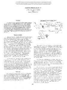
Figure 1: The coordinate system. The TFS is copmosed of multiple PUs at different positions and one Kicker for each transversal direction. The signals from the PUs, which correspond to the transversal beam displacements from the ideal trajectory, are delayed differently, such that they correspond to the same bunch. The driving signal at he kicker is an amplification of the the weighted sum of the delayed signals. Figure 2 shows a block diagram of the TFS. P UM
P U1
amp.
τ1 Σai xi
Kicker
τM
Beam
Figure 2: Block diagram of the TFS. Let xi be the signal at the pickup PUi , which is located at the position si along the accelerator ring. This signal corresponds to the beam transversal (horizontal or vertical) beam displacement x ˜i perturbed by noise z. xi = x ˜i + zi .
(1)
As vector notation one can write x=x ˜+z
(2)
06 Beam Instrumentation and Feedback T05 Beam Feedback Systems
487
c 2011 by IPAC’11/EPS-AG — cc Creative Commons Attribution 3.0 (CC BY 3.0) Copyright ○
INTRODUCTION
MOPO005
Proceedings of IPAC2011, San Sebastián, Spain
where x = [x1 , x2 , · · · , xM ]T denotes the vector of the signals from the M PUs, z = [z1 , z2 · · · , zM ]T denotes the noise vector from the PUs and x ˜ = [˜ x1 , x ˜2 · · · , x ˜ M ]T denotes the actual beam displacements at the PUs. The derivative of the beam transversal displacement at the Kicker at position s along the accelerator ring, which corresponds to beam direction at that position, can be estimated using the pickup signals xi1 and xi1 , i ∈ {1, 2, · · · , M } according to the vector summation approach introduced in [1] as x ¯
= αi1 xi1 + αi2 xi2
(3)
= αi1 x˜i1 + αi2 x˜i2 + αi1 zi1 + αi2 zi2
(4)
′
= x +z
(5)
where x′ is the actual beam direction at kicker position s, αi1 and αi2 are constants, which depend on the lattice functions of the accelerator, the positions si1 , si2 and s of PUi1 , PUi2 and the Kicker respectively. z denotes the noise part in the estimation of beam direction at the Kiker.
c 2011 by IPAC’11/EPS-AG — cc Creative Commons Attribution 3.0 (CC BY 3.0) Copyright ○
MATHEMATICAL DERIVATION In order to mitigate the noise part in the estimation of beam direction at the Kiker, we address here a new approach for calculating optimal weighted sum of the signals from multiple pickups. The idea of this approach is to average out the noise by estimating the beam direction at the Kicker position s using the signals from M PUs, i.e., three and more, in an optimal way, such that the noise power at the estimated signal is minimized and the the weighted sum of the actual beam displacemnets at the PUS without noise corresponds to the actual beam direction at the Kicker. The optimization problem can be formulated as [a1 , · · · , aM ] = argmin E| a1 ,··· ,aM
s.t.
M X
M X
a i z i |2
(6b)
i=0
In order to find a solution for this optimization problem, we first reformulate it using vector summations of PU pairs signals like in the following: The beam direction at the position s can be estimated using any two of the M PUs signals according to vector summation. Let’s take as pairs x1 with x2 , x2 with x3 and so on and so forth till xM−1 with xM . This can be written in matrix notation as follows x1 x ¯i . .. (7) = Λ .. . x ¯M−1
xM = Λ˜ x + Λz ′ x = ... + Λz ′
x
488
α11 0 Λ= 0 . .. 0
(8) (9)
α12 α22 0 .. . ···
0 α23 .. . ··· 0
0 .. . .. 0 . ···
··· ···
0 0
0 .. .
···
αM−1M−1
Let w = [w1 , w2 , · · · , wM−2 , 1 −
M−2 P
··· αM−1M (10)
wi ]T then the
i=1
following holds
x¯i wT ... = x′ +wT Λz ∀w1 , · · · , wM−2 ∈ RM−2 x ¯M−1 (11) The optimization problem given in Eq. 6 is equivalent to finding the optimal vector wopt which minimizes the noise power in Eq. 11, i.e., E|wT Λz|2 , Where T [a1 , · · · , aM ]opt = wopt Λ.
(12)
The reason for this equivalence is that both problems have the same number of dimensions in addition to describing the same unbiased estimator with minimum noise in both . The vector w can be written in the following form ˆ + eM−1 w = Dw
(13)
ˆ = [w1 , w2 , · · · , wM−2 ]T , w
(14)
eM−1 = [0, 0, · · · , 0, 1]T ∈ RM−1×1
(15)
where
(6a)
i=1
ai x ˜i = x′
where the matrix Λ is given through the vector summation of the above mentioned PUs pairs as
and D ∈ RM−1×M−2 with all-ones on the main diagonal, all −1 on the last row and zeros elsewhere. Therefore, the noise power is given by PN
= E|wT Λz|2 ˆ T DT ΛRzz ΛT Dw ˆ = w ˆ T DT ΛRzz ΛT eM−1 + eTM−1 DT ΛRzz ΛT eM−1 +2w
ˆ opt can be found by setting the An optimal solution w derivative of PN with respect to w to zero and solving ∂PN =0 (16) ˆ w ∂w ˆ opt which leads to ˆ opt = −(DT ΛRzz ΛT D)−1 DT ΛRzz ΛT eM−1 (17) w Finally the optimal weights [a1 , · · · , aM ]opt can be calculated using Eq. 12 and Eq. 17. 06 Beam Instrumentation and Feedback T05 Beam Feedback Systems
Proceedings of IPAC2011, San Sebastián, Spain
RESULTS
MOPO005
0
Neighbour PUs Best PUs Combination −2
Noise Level (db)
In this section we show simulation results of the above adressed approach for the Synchrotron SIS 18 at the GSI. In the SIS 18 there are 12 beam position PUs for the horizontal and the vertical directions, which are located periodically along the synchrotron ring. There is also one feedback kicker for each transversal direction. The phase differnce between each two neighbour pickups corresponds to the machine tune divided by 12. For the horizontal dircection we have phase differnce between each two neighbour pickups of 129.3◦ , and 99.2◦ for the vertical dircection. During acceleration focusing changes continuously from so called doublet mode to triplet mode, which changes the betatron functions during opreation. The simulation results for the doublet mode, i.e., at the beginning of acceleration dirctly after injection, for both of the transversal and vertical directions will be shown. The technical parameters for these two scenarios are shown in Table 1. βpu and αpu are the values of the betatron functions at the PUs positions. βk and αk are the values of the betatron functions at the kicker position. ∆φ◦1 denotes the phase difference between the kicker position and the position of the closest PU.
−4
−6
−8
−10
−12 2
4
6
8
10
12
Number of Pickups
Figure 3: Noise reduction for horizontal direction of doublet mode. 0
Neighbour PUs Best PUs Combination
−1
mode Doublet x Doublet y
βk
βpu
αk
αpu
∆φ◦1
26.44 6.69
6.67 20.06
-2.22 -0.54
0.67 1.04
105.7 74.5
−3 −4 −5 −6 −7
The results are depicted in Fig. 3 and Fig. 4 for horizontal and vertical directions of doublet mode respectively. As a reference we take the noise power for using the closest two PUs to the kicker, which are the currently used PUs for the TFS in the SIS 18. For each dirction of doublet mode two curves are depicted, i.e. the noise power reduction by using increasing number of closest PUs to the kicker and the noise power reduction by using the best combinations of increasing number of PUs. The figures show, that the noise power can be reduced by about 6.5 db for horizontal direction and about 3.5 db for vertical direction just by using the best combination of two PUs rather than using the closest two pickups to the kicker. Furthermore, one can notice from the figures that noise power can be reduced by about 11.5 db for horizontal direction and about 8.5 db for vertical direction by using the whole 12 PUs in the SIS 18. It is also interesting to notice, that using more than the best 8 PUs for horizontal direction and 9 PUs for vertical direction doesn’t bring any noticeable enhancement.
CONCLUSION A new technique for reducing noise power by using multiple PUs in TFS has been addressed in this work. Simulation results has shown enhancement by using this technique. However we should have in mind the implementation challenges of this technique, where multiple PUs sig06 Beam Instrumentation and Feedback T05 Beam Feedback Systems
−8 −9 2
4
6
8
10
12
Number of Pickups
Figure 4: Noise reduction for vertical direction of doublet mode. nals must be synchronized.
REFERENCES [1] R. Rojko, “New Concepts for Transverse Beam Stability in High-Current Heavy-Ion Synchrotrons”, Ph.D. Thesis, Technische Universitaet Darmstadt, July 2003. [2] M. Kirk, U. Blell and O. Boine-Frankenheim, “Maschinenexperimente zur transversalen Strahlanregung und Inbetriebnahme des TFS am SIS”, GSI report, Darmstadt, November 2002, http://www.gsi.de. [3] P. J. Bryant, “Beam transfer lines”, Jyvaeskylae 1992, Proceedings, General accelerator physics, Vol. 1, 219-238. CERN Geneva - CERN-94-01 (94/01,rec.Mar.). [4] K. Wille, “The physics of particle accelerators: an introduction”, Oxford University Press (2000), New York. [5] P. J. Bryant and K. Johnsen, “The Principles of circular accelerators and storage rings”, Cambridge, UK, Univ. Pr. (1993) p. 357.
489
c 2011 by IPAC’11/EPS-AG — cc Creative Commons Attribution 3.0 (CC BY 3.0) Copyright ○
Table 1: Technical Parameters for Doublet Mode
Noise Level (db)
−2