This paper present a 3D router design which can support seven requests ... Key words: 3D Network on Chip Turn model Negative-First routing algorithm FPGA ...
World Applied Sciences Journal 32 (8): 1499-1505, 2014 ISSN 1818-4952 © IDOSI Publications, 2014 DOI: 10.5829/idosi.wasj.2014.32.08.1254
A Turn Model Based Router Design for 3D Network on Chip Bouraoui Chemli and Abdelkrim Zitouni Electronics and Micro-Electronics, Laboratory, Faculty of Sciences of Monastir, Monastir University, Tunisia Abstract: Network on chip (NoC) is emerging as a new trend for a System on chip (SoC) design. The key advantages of NoC are high performance and scalability. Despite those improvements over the conventional shared-bus based systems, NoC are not shown as the ideal solution for the future SoC. Recently, with the three dimension (3D) technology. The 3D NoC has been designed to overcome the high power consumption, highcost communication and low throughput. This paper present a 3D router design which can support seven requests simultaneously. The traditional Turn Model technique used in 2D NoC has been extended in the case of 3D NoC in order to avoid deadlock conflicts. Experimental results in terms of area, power and clock frequency, relatively to 2D NoC and others famous 3D routers has been discussed. Key words: 3D Network on Chip Performances
Turn model
Negative-First routing algorithm
INTRODUCTION With the development of technology, on-chip transistor densities are increasing rapidly and overall system performance and cost become increasingly dependent on the efficiency of the interconnection scheme [1]. NoC [2-4] has been introduced as a promising solution for the on-chip communication system. Concurrently, future applications are becoming more complex, needing a scalable architecture to meet high throughput, low latency and parallel computing. This has made conventional two dimensions NoC faced lots of challenges and limit the on-chip communication performance. The most potent solution to address these problems is the design of 3D NoC. In the past few years, three-dimensional integrated circuits (3DIC) [5] has emerged as the potential solution for the interconnect bottleneck. 3D on-chip [6] refers to a stack multiple die in the vertical axis which are interconnected using through silicon via (TSV). 3D ICs offer many advantages over the traditional 2D chip like shorter global interconnects; lower interconnect power consumption and higher performance. Combining NoC structure and the benefits of the 3D integration technology offers a promising 3D NoC architecture. This architecture satisfies the high requirements of future SoC. Corresponding Author:
FPGA Implementation
In this paper, we propose deadlock free router architecture design for the use in 3D mesh NoC using the Negative-First algorithm, credit based flow control strategies, input queuing buffering and wormhole switching techniques. The rest of the paper is organized as follows, next section to summarize previous works on 3D network on chip to provide appropriate background. Section 3 details the proposed NoC router architecture. Section 4 shows the performance results. In section 5, we conclude the paper. Related Work: 3D NoC is emerging as truly wide studies research topic. Many works provides a significant performance and solve various challenges in 3D NoC designs. Different 3D NoC architectures have been introduced in [7-10]. The most used one is the 3D mesh thanks to its scalability in term of area, regular structure and simplicity. The 3D mesh is the simple extension of the popular planar structure 2D mesh. A. B. Ahmed et al. [11] introduced a 3D NoC called OASIS. This structure is essentially a 3D mesh network used a fault-tolerant routing algorithm named Look-Ahead-Fault-Tolerant (LAFT) wish reduces the communication latency and enhances the system performance. However, they focus on decreasing the latency and did not consider about increasing of power overhead. S. Pasricha et al. [8] investigated in fault-tolerant routing scheme in 3D NoC
Bouraoui Chemli, Electronics and Micro-Electronics, Laboratory, Faculty of Sciences of Monastir, Monastir University, Tunisia.
1499
World Appl. Sci. J., 32 (8): 1499-1505, 2014
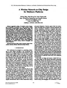
Fig. 1:.3D NoC based on 3x3x3 mesh topology and presented the 4NP-First routing algorithm. This turn model provides better resilience and adaptively against fault compared to stochastic random walk routing scheme. However, they had used two input buffer for each vertical channels, it consumes more area comparing to our architecture. In [12] the authors proposed a 3D network on chip which associates an efficient fault-tolerant routing algorithm (HLAFT) and a deadlock-recovery technique (RAB). This technique takes advantage of look-ahead routing to detect and remove deadlock. The problem with this solution is the considerable additional hardware complexity. In [13] the authors presented a Fault-Tolerant Mesh for 3D NoC. They used the k shortest paths algorithm to develop a deadlock-free routing scheme. This proposed routing scheme reduces the calculation time and provide enough backup paths to satisfy the fault-tolerance ratio so make the system more robust. However, the router is complex and costly in term of hardware and implementation. In this paper, we propose a router for 3D NoC using the Negative-First 3D turn model routing algorithm. This turn model introduces some routing restriction to prevent from deadlock. It takes advantage of fault tolerance while retaining a low cost and being simple to implement. 3D NoC architecture: The proposed 3D router is the extension of the 2D router developed previously in our research team [14]. Figure 1 represents 3D NoC based on 3x3x3 mesh topology and use the wormhole switching technique. Each switch can have a maximum number of seven bidirectional ports, one for each direction (local, north, south, east, west, up and down). The number of
ports can be reduced depending on the position of the switch in the network. Each switch must have a unique address in the network. To simplify the routing on the network, this address is expressed in XYZ coordinates, where X represents the horizontal position; Y represents the longitudinal position and Z the vertical position. The data flow through the network is a wormhole routing. Our 3D NoC uses credit based flow control strategies. We have adopted a deadlock free routing algorithm called Negative-First routing. A dynamic arbiter is used to support Quality of Service requirements. In order to resolve any output port conflicts, the arbiter uses the round-robin scheme and a priority scheduler module to assign the adequate output port to the highest priority packet. The routing function is distributed in the router and can route seven packets coming from different input ports to seven different output ports at the same time. The Parallel operation of these routing modules minimizes the latency of the router and the average latency of the network. Topology: 3D NoC, as illustrated in Figure 1, is a simple 3x3x3 mesh topology where adx, ady and adz are attributed to each router and deflne its X, Y and Z coordinates respectively. The mesh topology is chosen for our design thanks to its several properties like regularity, concurrent data transmission and controlled electrical parameters [15]. Each switch can have a maximum of seven input ports, where flve are dedicated to the intra-layer connection (local, north, south, east and west) and the other two ports (Up and Down) ensure inter-layer communication. The number of ports depends 1500
World Appl. Sci. J., 32 (8): 1499-1505, 2014
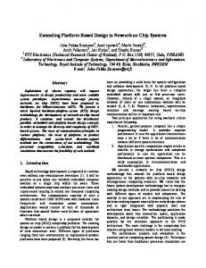
Fig. 2:.3D router architecture on the position of the switch in the design, since we have to eliminate any unused links that have no connections with other switches in order to reduce power consumption. Input Controller: The input controller contains three main blocks, the link controller, FIFO and the output controller. Its role is to manage the data flow of the dependent input ports and establishes the communication with the other neighboring blocks. There is one input controller for each input port. Thus, the switch contains up to seven input controller. This block receive “grant” signal from the switch allocator indicating the response to the request of the output ports. In addition, the “credit” signals from the credit switcher indicate the status of the input ports of neighboring routers. The “RFplein” signal from the routing function indicates the possibility to identify the destination address of the packet. The link controller receives a packet flits from the Output port of the adjacent router and stores them in the buffer using GALS techniques. The output controller constitutes a bridge that connects the FIFO and the output port destination. Router Architecture: The proposed 3D router mainly include the input module, switch allocator, semi-crossbar and the credit-switcher. The architecture of the router is shown in Figure 2.
Routing Algorithm Scheme: In [16], Glass introduced the turn model concept for partially adaptive 2D mesh routing algorithm, which are deadlock and livelock free without the addition of virtual channels. Particularly, in wormhole networks, deadlock can occur when packets are involved in a cyclic dependencies waiting that cannot be resolved. When traveling between switches in a 2D mesh, a packet can pursue four directions: East, West, North and South. The packet may take eight possible turns in each path. A turn in this context refers to a 90-degree change of passing direction for the packet. Prohibit at least two turns results on breaking cyclic dependencies between packets and ensure deadlock free algorithm. In 3D mesh, there are 24 possible 90-degree turns. In order to prevent deadlock we have to prohibit at least two turns in each plans (x,y), (x,z) and (y,z).Three turn models were proposed by Glass are west-first, north-last and the negative-last. We are focusing on the last one thanks to its symmetric and simple extension in 3D. The most used turn model scheme is the NegativeFirst routing algorithm due to its simplicity and scalability. In order to simplify the terminology, the –x direction is west, the +x direction is east, the –y direction is south, the +y direction is north, the –z direction is down and the +z direction is up. The Negative-First 3D turn model routing algorithm consist to route a packet first adaptively throw –x, –z and –y and then adaptively +y, +x and +z. As shown in Figure 3.a, the forbidden turns are the two from
1501
World Appl. Sci. J., 32 (8): 1499-1505, 2014
Fig. 3: (a) prohibited turns in the 3D router, and (b) six turns allowed (solid arrows) in negative first routing the positive direction to a negative direction. As shown in Figure 3.b, these turns are from the six dependency cycles, two from three plans (x,z), (y,z) and (x,y). We choose the Negative-First routing algorithm, which is based upon 3D turn model, which has the best performance. Since it’s simple to implement, it is free of deadlock and livelock. This technique doesn't require the packet ordering. At each inputport, in order to define the next output port, the router compares the actual addresses of the router and the destination addresses of the packet: If dstx is larger than adx then the next port will be px, else the next port will be nx. If dsty is larger than ady then the next port will be py, else the next port will be ny. If dstz is larger than adz then the next port will be pz, else the next port will be nz. If dstx is equal to adx, dsty is equal to ady and dstz is equal to adz then the next port will be the local port. Switch Allocation: The switch allocator is compounded by seven arbiter module similar to those presented in Figure 4; each one contains a priority comparator, Muller
Fig. 4: Arbitre module port and synchronous round robin arbiter. Each input port has its own switch allocator. In this manner, the number of inputs and outputs change within the input port type. For example, the switch allocator of port nz has more input and output signals then the port pz. It’ role is to select the adequate output port for the requester input port. Based on the packet priority, this scheme serves all the requests in a fair way when several flits request the same output port.
1502
World Appl. Sci. J., 32 (8): 1499-1505, 2014
Fig. 5: (a) semi-crossbar circuit,(b) multiplexer of port p, and(c) multiplexer of port n Semi-Crossbar Traversal: The semi-crossbar, as presented in Figure 5(a), interconnects the output port with the input port of the next router. The arbiter of the switch allocator sends the select signal to the crossbar to ensure the interconnection with the adequate output port. The input module sends the data, bop, req and eop signals. Depending on this information; the crossbar sends flits to the appropriate ports as illustrated in Figure 5. When all the flits are transmitted, the eop bit informs the semi-crossbar that the operation is done and the used channel can be free in order to be exploited by another flit. The semi-crossbar contains seven multiplexers. The output ports pz, py, px and the local port may receive flits from any port types. The output of it’semi-crossbar is connected to all input ports in the switcher as presented in Figure 5.b. The multiplexer for the output ports nz, ny and nx as shown in Figure 5.c can receive flits only from local port or ports type n. Credit Switcher: In order to use resources of the network such as buffer capacity and channel bandwidth in an efficient way and also to avoid overflow, a flow control scheme is implemented to manage the resources allocation in a network. Credit-based, handshaking and AKC/NACK are the most flow control used in NoC. In Credit-based flow control, before forwarding any flits, the receiver sends credit to the sender about the number of empty buffers, according to this information the sender forward flits to the receiver. Each time the
Fig. 6: Demultiplexer used in ports type p and n sender forward flits, it decrement its credit number. Credit-based flow control shows remarkable performance comparing to the handshaking flow control scheme [17]. The credit switcher based on demultiplexer connects the credit signal of the output port to the correspondent input controller. One demultiplexer is allowed to each port indeed the switcher contains up to seven demultiplexers similar to those represented in Figure 6. Ports nz, ny, nx or local port may be connected to all ports in the switcher, the demultiplexer shown in Figure 6.a is used for this ports type. Ports pz, py or px can be connected to port type p or local, Figure 6.b illustrated the demultiplexer used for ports type n. RESULTS The proposed router is specified in VHDL language at RTL level and implemented on a Xilinx FPGA board using ISE 13.1 tool. The target device is the FPGA Virtex5
1503
World Appl. Sci. J., 32 (8): 1499-1505, 2014 Table 1: Sumilation Parameters Router Parameters
2D router
3D router
Buffer Depth Flit size (bit) Switching Flow control Scheduling Routing Target device
4 16 wormhole Credit based Dynamic arbiter Static XY Virtex2 XC2V6000
4 32 wormhole Credit based Dynamic arbiter Negative-First Virtex2 XC2V6000
Table 2: Performance comparison of the proposed router with other state of the art ones
Fig. 7: Results of the different router implementation on FPGA
Fig. 8: Comparison between 2D and 3D router hardware XC5VFX70T. In this section we present and discuss the synthesis results. The routers performance will be evaluated in terms of area, power consumption and clock frequency. Figure 7 summarizes the hardware complexity results of the different router implementations. For each type of router, we compare the complexity in term of area, power and speed. As we mentioned above, the number of inputs-outputs ports depend on the router’s location in the network. In this Figure, 7-Port represents a 3D router with both of Up and Down vertical ports, 6-Port represents a 3D router with Up or Down vertical port, 5-Port router represents a 2D router without any vertical port and 4-Port router presents the 2D router without any vertical port and without one horizontal port. As can be seen the router area increase with the addition of the number of ports. The 7-Port router needs more area then a 2D router due to the addition of the two vertical ports and a large crossbar. Table 1 shows the parameters used for the synthesis for both 2D and 3D router d esigns and Figure 8 gives an overview of the two systems architectures. We compered the 2D router previously designed by our research team [14] and the 3D router implementation. We can conclude that the logic utilization is increased by average of 49%, compared to the 2D router design. The increased number of CLB (Register, LUTs) is caused
Design
[18]
[19]
Our
[20]
Our
Number of ports Frequency (MHz) Area FPGA device
7 327 1391 Virtex-6
7 353 1273 Virtex-6
7 195 7847 Virtex-6
7 250 11550 Virtex-4
7 65 3557 Virtex-4
by the additional number of ports and buffers at each switch. In term of power consumption, we noticed a small overhead illustrated by 0.2%. Table 2 illustrates a comparison between our design and those proposed in [18-20]. The simplicity of our 3D router architecture reduces the hardware costs and increases the clock frequency. The area of our router is lower than the area of router presented in [20] which uses a buffer for each input port. It is also greater than the routers presented [18] and [19] because we use a routing function for each input port. The results show that our 3D router underperforms all other architectures in terms of maximal clock frequency. CONCLUSION The 3D NoC is a natural extension of the 2D NoC design, previously developed by our research team. In this paper, we showed the design and implementation of a scalable router design for packet-switched on-chip networks in SoC environment. The evaluation results show that in terms of area and power consumption 3D router underperforms the 2D router despite a higher operating frequency of the 3D router. As future works, we attempt to improve the reliability and the robustness of the proposed router against fault in our NoC 3D. A fault tolerant mechanism according to a set of traffics needs to be developed. REFERENCES 1.
1504
Daneshtalab, M., 2011. Exploring Adaptive Implementation of On-Chip Networks. Turun Yliopisto, University of Turku.
World Appl. Sci. J., 32 (8): 1499-1505, 2014
2.
Tatas, K., K. Siozios, D. Soudris and A. Jantsch, 2014. Designing 2D and 3D Network-on-Chip Architectures. Springer. 3. Salah, Y. and R. Tourki, 2011. Design and FPGA Implementation of a QoS Router for Networks-onChip. IEEE Proceeding of the 3rd International Conference on Next Generation Networks and Services, pp: 84- 89. 4. Fernandez-Alonso, E., D. Castells-Rufas, J. Joven and J. Carrabina, 2012. Survey of NoC and Programming Models Proposals for MPSoC. International Journal of Computer Science Issues, 5(2): 22- 32. 5. Xie, Y., J. Cong and S. Sapatnekar, 2010. ThreeDimensional Integrated Circuit Design. Springer. 6. Sheibanyrad, A., F. Pétrot, and A. Jantsch, 2011. 3D Integration for NoC-based SoC Architectures, Springer. 7. Ahmed, A., B. Abdallah, A. B. and K. Kuroda, 2010. Architecture and Design of Efflcient 3D Network-onChip (3D NoC) for Custom Multicore SoC”, IEEE computer society Proceeding of the International Conference on Broadband, Wireless Computing, Communication and Applications, pp: 67- 73. 8. Pasricha, S. and Y. Zou, 2011. A low overhead fault tolerant routing scheme for 3D Networks-on-chip. IEEE Proceeding of the 12th Int’l Symposium on Quality Electronic Design, pp: 204- 211. 9. Bahmani, M., A. Sheibanyard, F. Pétrot, F. Duboid and P. Durante, 2012. A 3D-NoC Router Implementation exploitingVertically-PartiallyConnected Topologies. IEEE Computer Society Proceeding of the Annual Symposium on VLSI, pp: 9- 14. 10. Ying, H., A. Jaiswal, T. Hollstein and K. Hofmann, 2013. Deadlock-free generic routing algorithms for 3dimensionalNetworks-on-Chip with reduced vertical link density topologies. Journal of Systems Architecture, 59(7): 528- 542 by Elsevier. 11. Ahmed, A.B. and A.B. Abdallah, 2013. Architecture and design of high-throughput, low-latency and fault-tolerant routing algorithm for 3D-network-onchip (3D-NoC). The Journal of Supercomputing (66) 3: 1507- 1532 by Springer.
12. Ahmed, A.B. and A.B. Abdallah, 2014. Graceful deadlock-free fault-tolerant routing algorithm for 3D Network-on-Chip architectures. The journal of parallel and distributed computing. (74) 4: 2229- 2240 by Elsevier. 13. Hsieh, K., B. Cheng, R. Gu and K. Shu-Min Li, 2011. Fault-Tolerant Mesh for 3D Network on Chip”, IEEE Proceeding of the 6th International Microsystems, Packaging, Assembly and Circuit Technology Conference, pp: 202- 205. 14. Chouchene, W., B. Attia, N. Abid, A. Zitouni and R. Tourki, 2011. A quality of service network on chip based on a new priority arbitration mechanism. IEEE Proceeding of the International Microelectronics Conference. pp: 1- 6. 15. Mirza-Aghatabar, M., S. Koohi, S. Hessabi and M. Pedram, 2007. An empirical investigation of mesh and torus noc topologies under different routing algorithms and trafflc models. IEEE Proceeding of the 10th Euromicro Conference on Digital System Design Architectures, Methods and Tools. pp: 19- 26. 16. Glass, C.J. and L.M. Ni, 1992. Adaptive routing in mesh-connected networks. IEEE Proceeding of the 12th International Conference on Distributed Computing Systems, pp: 12- 19. 17. Séverine, R., 2005. Evaluation des paramètres des réseaux sur puce. Ph.D Thesis. University of Montpellier II. 18. Agyeman, M.O. and A. Ahmadinia, 2011. An adaptive router architecture for heterogeneous 3D Networks-on-Chip. IEEE NORCHIP, pp: 1- 4. 19. Yu, X., L. Li, Y. Zhang, H. Pan and S. He, 2013. Mass Message Transmission Aware Buffer-Less Packet-Circuit Switching Router for 3D NoC. IEEE Proceeding of the 10th International Conference on Control and Automation, pp: 983- 986. 20. Tatas, K., C. Kyriacou, A. Bartzas, K. Siozios and D. Soudris, 2010. A novel NoC architecture framework for 3D chip MPSoC implementations. DATE’10 3D Integration at Design, Automation and Testing in Europe.
1505