ARTICLE International Journal of Advanced Robotic Systems
A Two Step Face Alignment Approach Using Statistical Models Regular Paper
Ying Cui1,*, Zhong Jin1 and Wankou Yang2 1 School of Computer Science and Engineering, Nanjing University of Science and Technology 2 School of Automation, Southeast University * Corresponding author E-mail:
[email protected]
Received 20 Jun 2012; Accepted 08 Aug 2012 DOI: 10.5772/52207 © 2012 Cui et al.; licensee InTech. This is an open access article distributed under the terms of the Creative Commons Attribution License (http://creativecommons.org/licenses/by/3.0), which permits unrestricted use, distribution, and reproduction in any medium, provided the original work is properly cited.
Abstract Although face alignment using the Active Appearance Model (AAM) is relatively stable, it is known to be sensitive to initial values and not robust under inconstant circumstances. In order to strengthen the ability of AAM performance for face alignment, a two step approach for face alignment combining AAM and Active Shape Model (ASM) is proposed. In the first step, AAM is used to locate the inner landmarks of the face. In the second step, the extended ASM is used to locate the outer landmarks of the face under the constraint of the estimated inner landmarks by AAM. The two kinds of landmarks are then combined together to form the whole facial landmarks. The proposed approach is compared with the basic AAM and the progressive AAM methods. Experimental results show that the proposed approach gives a much more effective performance. Keywords face alignment, active appearance model, active shape model
1. Introduction In recent years, with the rapid development of biometrics, artificial intelligence and the new generation www.intechopen.com
of human‐computer interaction technology, the face‐ related image processing techniques, such as face recognition, facial expression analysis, face pose estimation, face image encoding, etc., have attracted the attention of many researchers. However, these techniques require the facial feature point information that is obtained from the image or video as a precondition. That is, we first need to align the face to locate the facial landmarks and extract the corresponding facial feature information. The facial landmarks roughly include the contour points of eyes, mouth, nose, eyebrows, chin and cheeks. As the human face is non‐rigid, the accuracy of face alignment is affected by many factors, such as facial size, position, posture, expression, age, as well as the hair, glasses and light changes. A literature review shows that face alignment is still a difficult problem far from being resolved. Many methods have been proposed for face alignment, including the Active Contour Model (ACM) [1], the Deformable Template [2, 3], Elastic Graph Matching [4, 5], the Active Shape Model (ASM) [6], the Active Appearance Model (AAM) [7, 8] and so on. Among them, AAM is the most effective. Int J Adv Sy, 2012, Vol. 9, 150:2012 YingRobotic Cui, Zhong Jin and Wankou Yang: A Two Step Face Alignment Approach Using Statistical Models
1
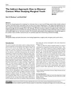
AAM was proposed by Cootes et al. in 1998 [7]. Its idea can be traced back to ASM. Face alignment using AAM is relatively stable, but is known to be sensitive to initial values and not robust under inconstant circumstances. In order to strengthen the ability of AAM, many improvements have been proposed [9‐11]. Under various face poses and illumination conditions, the contour of the outer parts of the face (like the chin and the cheeks) tends to be more variant than the inner parts of the face (like the eyes, eyebrows, nose and mouth). The outer contour of the face may be easily affected by the background of the face images. Daehwan Kim et al. [12] utilized the fact and proposed a progressive AAM‐based face alignment. The progressive AAM constructs two AAM models: the inner face model and the whole face model. It first uses the inner face model to locate the inner points of the new input face and then uses them to estimate a better initial shape for the whole face model, and lastly uses the whole face model to locate all facial feature points with the estimated initial shape. However, for inconstant circumstances, AAM couldn’t locate the outer contour accurately though it is better initialized. As pointed out by Cootes et al. [13], ASM is faster and achieves more accurate feature point location than AAM; so we can turn to ASM, which is the source of AAM, to find a better solution. Both ASM and AAM are based on the Point Distribution Model (PDM) and construct two models: the shape model and the texture model. They share the same shape model. But for the texture model, ASM only models the image texture in the neighbouring of each landmark point, whereas AAM uses a model of the appearance of the entire facial region. There are many differences between AAM and ASM, and each has advantages over the other. ASM is faster and has a broader search range than AAM, whereas AAM gives a better match to the texture. Therefore, some researchers have combined the two methods to improve the performance [14, 15]. In this paper we make use of the idea of “progressive” and propose a two step approach for face alignment by combining AAM and ASM. In the first step, we use AAM to locate the inner facial landmarks (Seeing Figure 1(a)). In the second step, we use ASM to locate the outer facial landmarks (see Figure 1(b)) with the constraint of the inner facial landmarks. Finally the two kinds of landmarks are combined to a whole (see Figure 1(c)). Experimental results confirm that our approach is effective and robust for face alignment. The rest of the paper is organized as follows. In section 2 the AAM and ASM are reviewed. In section 3 the improvements to AAM and ASM, and our face alignment approach are presented. The experimental results are given in section 4 and finally the conclusion is given in section 5.
2
Int J Adv Robotic Sy, 2012, Vol. 9, 150:2012
(a) Inner shape (b) Outer shape (c) Whole shape Figure 1. Shape models of the AAM and ASM
2. Model Description ASM and AAM share the same shape model, but for the texture model, ASM only models the image texture in the neighbouring of each landmark, while AAM uses a model of the appearance of the whole facial region. Let D be a training set D I i , vi iN1 , where N is the number of the training images, Ii is the i‐th image and T vi x1 , y1 , x2 , y2 , , xn , yn is the i‐th corresponding shape formed by n landmarks of Ii. 2.1 Shape Model The shape S can be described by n facial landmarks S ( x1 , y1 , x 2 , y 2 ,..., x n , y n ) T in the image. ASM and AAM both allow linear shape variation. This means that the shape S can be expressed as a base shape S0 plus a linear combination of k shape vectors {Si}: k
S (p) S 0 pi S i
(1)
i 1
where p ( p1 , p 2 ,..., p k ) T is the shape parameter. The base shape S0 and the k shape vectors {Si} are computed by applying Principal Component Analysis (PCA) to the training shapes (from a hand‐labelled training set). The base shape S0 is the mean shape and the shape vectors {Si} are the k eigenvectors corresponding to the k largest eigenvalues {i } . The shape parameter p defines a set of parameters of a deformable model. By varying the elements of p we can vary the shape S(p) using Eq.(1). The variance of the i‐th parameter pi across the training set is given by i . To ensure that the shape generated is similar to those in the original training set, the following limit is applied to pi :
pi 3 i
(2)
This limit prevents the synthesized shape from distorting. 2.2 Appearance model for AAM The appearance of AAM is defined within the mesh of the mean shape of the training set, which also is the base
www.intechopen.com
shape S0 in the shape model. Let M0 denote the set of pixels {x = (x, y)T} that lie inside the mesh of S0. The appearance model of AAM is then an image A(x) defined over the pixels x M 0 . Similar to the shape S, the appearance A(x) can be expressed as a base appearance A0(x) plus a linear combination of h appearance images {Ai(x)}: h
A( x ) A0 ( x ) qi Ai ( x ) x M 0 (3) i 1
where the coefficients qi are the appearance parameters. The base appearance A0(x) and appearance images {Ai(x)} are computed by applying PCA to the shape‐normalized training images. Each training image is shape‐normalized by warping the hand‐labelled training shape onto the mean shape S0. The base appearance A0 is the mean image and the appearance images {Ai} are the h eigenimages corresponding to the h largest eigenvalues. 2.3 Local profile models for ASM ASM forms one profile model for each landmark. The profile is a fixed‐length normalized gradient vector by sampling the image along the normal line which is orthogonal to the shape boundary at the landmark. During training on the hand‐labelled faces, the mean profile vector g and the profile covariance matrix R g are calculated at each landmark. The quality of fit of a new landmark is given by
f ( g s ) ( g s g )T Rg1 ( g s g ) (4) where gs is the profile of the new landmark. 3. A Two Step Face Alignment Approach The problem of ASM is that it easily converges to local minima and thus cannot obtain the global optimal solution. But for the outer contour of the face, which has significant gradient values, ASM can get accurate fitting results. To solve the local minima problem, we use AAM to locate the inner landmarks of the face and use the result to initialize and constrain ASM fitting. 3.1 Outline of Our Approach 1) Model Constructing a) Construct the whole shape model from the whole facial landmarks of the training faces. b) Construct the inner face AAM model from the inner facial landmarks of the training faces, including the inner shape model and the inner appearance model. c) Construct the outer face ASM profile models from the outer facial landmarks of the training faces.
www.intechopen.com
2) Model Fitting The first step—Using AAM to locate the inner landmarks: fit the inner face AAM model into a new incoming face. The second step—Using ASM to locate the outer landmarks: a) Use the similarity transformation [13] to translate the whole mean shape of the whole shape model to the estimated inner landmarks. The outer landmarks of the translated whole mean shape are then selected as the initial values of the ASM fitting. b) Fit the outer face ASM profile models into the new incoming face by applying a constraint in each iteration. 3.2 Extension to ASM The classical ASM uses a one‐dimensional profile at each landmark. As pointed by S. Milborrow et al. [16], using two‐dimensional “profiles” can give improved fits. We can select a square region around the landmark to form the 2D profile, which captures more information around the landmark. The region is displaced in two directions, which are orthogonal or tangent to the shape edge at the landmark respectively. In order to reduce the lighting effects, we use the VHE bands [17] to represent the RGB values of each pixel: V value – The value (intensity) in the HSV colour‐space. H modified hue – The angular hue, h, of an HSV representation modified to accommodate single‐ band storage. Since faces have little hue variation, the hue circle is here collapsed around the approximate circular mean, 0 and in the following way:
hmod {h2 h
if h otherwise (5)
E edge – The edge strength, calculated as the gradient magnitude,
g g x2 g y2
(6)
where gx and gy are horizontal and vertical gradient images obtained from numeric differential operators with a suitable amount of Gaussian smoothing. The VHE bands can effectively eliminate some impact of the lighting variation and improve the fitting robustness. For each landmark point, the selected 2D profile matrix is reshaped and normalized as a long vector G j . To reduce the dimension of G j , we also apply a PCA on it. The profile G j of the j‐th model point is then represented as a linear combination of a mean profile G0j and l basis
Ying Cui, Zhong Jin and Wankou Yang: A Two Step Face Alignment Approach Using Statistical Models
3
vectors Gi j :
4. Experiment l
G j G0j i Gi j (7) i 1
where i are the profile parameters. The basis vectors
G are the l eigenvectors corresponding to the l largest eigenvalues . i
j
j i
In order to validate the performance of our method, we have conducted extensive experiments and comparisons on the IMM database [18] and the BU‐3DFE database [19]. The point‐to‐point (pt‐pt) error is used to evaluate the fitting accuracy. The pt‐pt error is given by the difference between the estimated landmarks and the hand‐labelled landmarks:
Let b ( 1 , 2 ,..., l ) and j (G1j , G2j ,..., Gl j ) , when
E (S, S)
j
given a new profile g , the vector b can be computed by j T
j
j 0
b ( ) ( g G ) (8) j
The distance between g and the profile model can be defined as: l
d i 1
i2 (9) ij
where i are obtained of Eq.(8). During the search we sample profiles of the current candidate points and choose the one which gives the minimum distance value. 3.3 Constraint of the inner landmarks We use the estimated inner landmarks that are given by AAM to give a better initial shape by applying the similarity transformation to the entire mean shape of the whole shape model. Then, in each iteration of the ASM fitting, the estimated outer landmarks are joined together with the inner landmarks to form the whole shape S. The shape parameter p is then computed as follows:
p T ( S S0 ) (10) where S1 , S 2 , , S k , {Si} are the shape vectors and S0 is the mean shape of the whole shape model. The constraint of Eq.(2) is then applied on the parameter p. The two operations prevent the ASM fitting from converging to local minima.
1 n ( xi xi) 2 ( yi yi) 2 (11) n i 1
where S is the ground‐truth shape and S is the estimated shape. The fitting is considered to be successful if the pt‐ pt error is within three pixels.
The IMM database consists of 240 images of 40 people, exhibiting variations in pose, expression and lighting. Each image is annotated with 58 landmarks. Half of the images are selected for training and the rest for testing.
The BU‐3DFE database contains 2500 image of 100 subjects (56% female and 44% male). Each subject performed seven expressions in front of the 3D face scanner. With the exception of the neutral expression, each of the six prototypic expressions (happiness, disgust, fear, angry, surprise and sadness) includes four levels of intensity. Each image is annotated with 83 landmarks. 300 images are selected for training and the rest for testing.
The experiment results for the IMM face database are summarized in Table 1 and Figure 2, while the experimental results for the BU‐3DFE database are summarized in Table 2 and Figure 3.
The proposed approach is compared with the basic AAM [7] and the progressive AAM [12]. Table 1 and Table 2 show the pt‐to‐pt fitting errors and the failure rates of the three different methods, which show that the proposed approach produces the smallest fitting error. The progressive AAM produces a lower failure rate than the proposed approach dose on the IMM database, which is shown in the last column of Table 1. However, as shown in the last column of Table 2, the proposed approach produces a lower failure rate than the progressive AAM dose on the BU‐3DFE database, which has more complex expressions than the IMM database.
Algorithms AAM [7] Progressive AAM [12] Proposed Approach
Number of test images 120 120 120
Number of failures 14 9 12
Pt‐Pt Error/pixel 2.438 2.321 2.076
Failure Rate/% 11.67 7.50 10.00
Number of failures 115 89 82
Pt‐Pt Error/pixel 2.657 2.230 2.027
Failure Rate/% 5.23 4.05 3.73
Table 1. Face alignment results of the IMM database Algorithms AAM [7] Progressive AAM [12] Proposed Approach
Number of test images 2200 2200 2200
Table 2. Face alignment results of the BU‐3DFE database
4
Int J Adv Robotic Sy, 2012, Vol. 9, 150:2012
www.intechopen.com
(a) (b) (c)
(a) (b) (c)
Figure 2. Fitting result comparison on IMM database: (a) Result of AAM; (b) Result of Progressive AAM; (c) Result of the proposed approach
Figure 3. Fitting result comparison on BU‐3DFE database: (a) Result of AAM; (b) Result of Progressive AAM; (c) Result of the proposed approach
Some examples of the fitting results are cut into suitable sizes and shown in Figure 2 and Figure 3. The proposed approach locates the landmarks more accurately than do the AAM and the progressive AAM, especially for the outer contour and the mouth. In our approach, the AAM just constructs the inner face model in which the texture can be less limited by the shape information of the outer face, which is more variable. Therefore it can give a more accurate inner landmark locating result than that of the whole AAM model, particularly in the situation of pose variation and expression variation. 5. Conclusions In this paper a two step face alignment approach is presented by combining two statistical models, the AAM and ASM. The ASM has a broader search range than AAM. It is also less limited by the texture information, therefore it can give a much more accurate fitting result on the outer contour of the face. The proposed approach is compared with the basic AAM and the progressive AAM methods. The experimental results confirm that our approach gives a much more effective performance on face alignment. The relationship between the inner landmarks and the outer landmarks is now only linked up through a simple constraint. In future work we will dig deeper into the relationship between the two kinds of landmarks and the relationship between the two kinds of statistical models.
6. Acknowledgments This work is partially supported by the Natural Science Foundation of China under grant no. 60973098, 61005005 and 61125305. 7. References [1] M. Kass, A. Witkin, D. Terzopoulos. Snakes: Active Contour Models. International Journal of Computer Vision, 1(4), pp. 321‐331, 1981. [2] A. L. Yuille. Deformable Templates for Face Detection. Journal of Cognitive Neuroscience, vol. 3, no. 1, pp. 59‐70, 1991. [3] A. L. Yuille, P. W. Hallinan, D. S. Cohen. Feature Extraction from Faces Using Deformable Templates. International Journal of Computer Vision, vol. 8, pp. 99‐111, 1992. [4] M. Lades, J. C. Vorbruggen, et al. Distortion Invariant Object Recognition in the Dynamic Link Architecture. Pattern Analysis and Machine Intelligence, 42(3), pp. 300‐311, 1993. [5] L. Wiskott, J. M. Fellous, N. Kruger, C. v. d. Malsburg. Face Recognition by Elastic Bunch Graph Matching. IEEE Trans. On PAMI, vol. 19, No. 7, pp. 775‐779, 1997. [6] T. F. Cootes, C. J. Taylor, D. H. Cooper. Active Shape Models‐Their Training and Application. Computer Vision and Image Understanding, 61(1), pp. 38‐59, 1995.
www.intechopen.com
Ying Cui, Zhong Jin and Wankou Yang: A Two Step Face Alignment Approach Using Statistical Models
5
[7] T. F. Cootes, G. J. Edwards, C. J. Taylor. Active Appearance Models. Proc. European Conf. Computer Vision, 2, pp. 484‐498, 1998. [8] G. Edwards, T. Cootes, C. Taylor. Advances in Active Appearance Models. Proc. Intʹl Conf. Computer Vision, 1, pp. 137‐142, 1999. [9] F. Kahraman, B. Kurt, M. Gökmen. Robust Face Alignment for Illumination and Pose Invariant Face Recognition. IEEE Conference on Computer Vision and Pattern Recognition, pp. 1‐7, 2007. [10] H‐S. Lee , D. Kim. Tensor‐Based AAM with Continuous Variation Estimation: Application to Variation‐Robust Face Recognition. Pattern Analysis and Machine Intelligence, 31(6), pp. 1102‐1116, 2009. [11] Y. Su, D. Tao, X. Li, X. Gao. Texture Representation in AAM using Gabor Wavelet and Local Binary Patterns. International Conference on Systems, Man and Cybernetics, pp. 3274‐3279, 2009. [12] D. Kim, J. Kim, et al. Progressive AAM Based Robust Face Alignment. World Academy of Science, Engineering and Technology, pp. 112‐117, 2007. [13] T. F. Cootes and C. J. Taylor. Statistical Models of Appearance for Computer Vision. Technical Report, University of Manchester, 125 pages, 2004. (www. face‐rec. org/algorithms/AAM/app_models. pdf)
6
Int J Adv Robotic Sy, 2012, Vol. 9, 150:2012
[14] S. Schreiber, A. Stormer, G. Rigoll. A hierarchical ASM/AAM approach in a stochastic framework for fully automatic tracking and recognition. Proc. IEEE Int. Conf. Image Process, pp. 1773–1776, 2006. [15] J. Sung, T. Kanade, D. Kim, A unified gradient‐based approach for combining ASM into AAM. International Journal of Computer Vision, vol. 75, no. 2, pp. 297–309, 2007. [16] S. Milborrow and F. Nicolls. Locating Facial Features with an Extended Active Shape Model. Proc. European Conf. Computer Vision, Part IV, pp. 504–513, 2008. [17] M. B. Stegmann, R. Larsen R. Multi‐band modeling of appearance. Image and Vision Computing, 21(1), pp. 61‐67, 2003. [18] M. M. Nordstrøm, M. Larsen, J. Sierakowski, and M. B. Stegmann. The IMM face database—An Annotated Dataset of 240 Face Images. Technical Report, Informatics and Mathematical Modelling, Technical Univ. of Denmark, DTU, May 2004. [19] L. Yin, et al. A 3D Facial Expression Database For Facial Behavior Research. The 7th International Conference on Automatic Face and Gesture Recognition (FG2006). IEEE Computer Society TC PAMI. Southampton, UK, April 10‐12 2006. pp. 211‐216.
www.intechopen.com