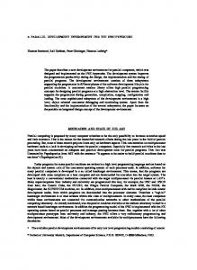
A UAV Test and Development Environment Based on Dynamic System Reconfiguration Osamah A. Rawashdeh, Garrett D. Chandler, and James E. Lumpp, Jr. University of Kentucky Department of Electrical and Computer Engineering Lexington, KY 40506, USA +1-859-257-8042
[email protected],
[email protected],
[email protected] ABSTRACT This paper describes ongoing research to develop a framework for implementing dynamically reconfiguring avionics and control systems for unmanned aerial vehicles (UAVs) and a test and development environment for experimental UAVs. The framework supports graceful degradation, where hardware and software failures cause a reduction in the quality or capability of the control system but does not result in total system failure. The approach uses a graphical specification representing modular software interdependencies and a runtime system manager that reconfigures the system. The techniques are currently being applied to the design of UAV control systems as part of the BIG BLUE Mars airplane testbed project at the University of Kentucky.
Categories and Subject Descriptors B.8.1 [Performance and Reliability]: Reliability, Testing, and Fault-Tolerance.
General Terms Design, Reliability, Experimentation
Keywords UAV, Avionics, Flight Control, Embedded Systems, Dynamic Reconfiguration, Fault-Tolerance
1. INTRODUCTION The development and deployment of unmanned aerial vehicles (UAVs) can be significantly enhanced by an avionics and control architecture capable of reconfiguring dynamically. The ability for control systems onboard to automatically respond to intermittent and permanent software and hardware failures enables functionality to degrade gracefully [1]. Likewise, the ability of such a system to incorporate additional processing and sensing
resources on the fly has potential to expedite the test and development of such a system. Our approach to specifying and creating a dynamically reconfiguring system involves two primary elements: a graphical specification methodology and a system manager to initiate and manage the system reconfiguration. The graphical specification encapsulates the software into modules and shows the dependencies among the producers and consumers of data. These dependency graphs (DGs) also enable the specification of similar software modules with alternate algorithms that require different amounts of resources, number of inputs, and input data qualities. A DG, annotated with bandwidth, processing time, and memory requirements, is stored in the system manager. The manager tracks the availability of resources and decides how to best use these to meet the requirements of the DGs and then instantiates this configuration by scheduling modules onto a networked set of processing elements. Software modules can detect failure of hardware or software resources and report them to the manager. The system definition and implementation approach presented has many benefits. The DGs clearly show the relationships among software modules and the data requirements of each. The DGs allow a new configuration to be determined at run-time. This enables the graceful handling of single faults as well as combination of faults that were not considered at design time. The ability of such a system to scale itself relative to the available resources maximizes its effectiveness. Also, the framework is capable of supporting traditional fault tolerance techniques, such as fail-over programming, N-version redundant calculations, and voting. This paper is organized as follows: In Section 2, related work is briefly discussed. In Section 3, the specification of application software using the dependency graphs is presented with an overview of the hardware architecture. The runtime behavior of the system is also described in this section. The application to a UAV test and development environment is described in Section 4. Current status of our research is described in Section 5. The paper is summarized in Section 6.
2. RELATED WORK Architectures for safety-critical runtime reconfiguration have architectures use an a priori set configurations) to simplify the
avionics systems capable of been proposed [2]. These of specifications (i.e., possible assurance of critical system
components. Degraded operation is facilitated on a higher level than our framework by providing complete backup sub-systems (hardware and software) that may have different functional qualities. Adaptive flight control systems are being developed that allow control systems to adapt to changes in the airframe (e.g., failure of a control surface) [3]. Our framework compliments this type of system by allowing continued operation in spite of failure of computer control components. The software module dependency graphs used in our framework share some aspects with success trees, used in modeling industrial systems for fault diagnosis and risk analysis [4]. Our dependency graphs can be viewed as extended success trees. We include gates that allow the specification of purely optional objects as well as the annotation of objects with quality values. Hence, our graphs show the flow of data instead of the binary values “operational” and “non-operational” exhibited in success trees. Dynamic reconfiguration middleware has been developed for high performance computer networks that provide software implemented fault tolerance (SIFT) such as Chameleon-ARMORs [5], RT-ARM [6], and real-time CORBA [7]. The open control platform (OCP) built on top of real-time CORBA has been developed to allow easy reconfiguration based on changing application requirements and for online upgrades as well as for maintaining viability. OCP also provides an abstract API to a heterogeneous networked environment to simplify controls application development [8]. A major focus of the OCP effort is on “safe” transitioning between control system alternatives. As opposed to using middleware, we believe that including explicit fault tolerance into the application design can reduce overhead associated with middleware services, making it more suitable for embedded systems. It is hoped that the explicit definition of fault tolerance also results in an integrated system model that can simplify assurance. The RoSES project is defining a framework to enable analysis and design of scalable gracefully degrading distributed embedded systems [9]. The RoSES reconfiguration algorithm finds all possible software configurations of the system for every hardware configuration and selects the highest utility software configuration to run. Finding a new configuration is done while the system is offline and focuses on non-critical functions, or features, of the system. The Chameleon project [10] (not related to [5]) is developing formal modeling techniques to specify and analyze the behavior of weakly-dependable dynamically reconfiguring systems. Chameleon uses an object oriented approach, creating a structural hierarchy, to model a system. The focus is on prediction and testability of configurations. All possible configurations are testable at design time. Our framework captures the redundancy in application software in DGs that clearly show the dependencies among the application’s software modules. These DGs are then used by a system manager to find favorable configurations of the application by scheduling modules based on the availability of
resources. The dependency graphs may also be useful in performing reliability analysis of the system. This paper describes our techniques and current status in developing our design framework. Our work is concerned with finding viable implementation techniques of dynamically reconfiguring real-time and safety-critical systems. We focus on the problem of graceful degradation on small UAVs that employ a controller area network (CAN) bus for interconnection. We are also examining the wireless extension of the network to allow computation to migrate to external (e.g., ground based) computing resources.
3. DESIGN FRAMEWORK 3.1 Software Specification Dependency graphs provide the basis for determining system configurations and making scheduling decisions [11]. Dependency graphs are directed graphs that specify the flow of data and the dependencies among software modules. A software module is a quantum of executable code that is schedulable by the OS running on a processing element. The software architecture of an application is represented as a set of dependency graphs for each system function (e.g., system output). DGs show the flow of information from input devices to output devices through a series of software modules that perform the required computations. Data variable nodes represent the information passed between modules. The data variable requirements of a software module are represented in the graphs by a set of interconnection symbols (comparable to logic gates). The software modules form the basic degradable units of our architecture.
Software module
Software module V1 Software module V2 Software module V3
m
Data Variable
Input Device Output Device
Figure 1. Nodes in a DG
A software module with a single operating mode is represented as a square node (top of Figure 1). The node is labeled with the function name. Modules with more than one operating mode can use one or more combinations of input variables and produce one or more quality versions of output variables. A three mode software module is shown in Figure 1. Data variables are outputs of software modules and are connected to their source module by an edge. Data variables are also inputs to software modules and are connected to their destination modules through interconnection symbols (discussed below). A data variable is represented as a circular node in the DGs (Figure 1). They are labeled with their name and an integer m that specifies the number of different quality versions available. There are four interconnection gates used in DGs. All gates have data variables or outputs of other gates as inputs. The output of any gate connects to the input of another gate or to exactly one software module. The first gate is the k-out-of-n OR gate (Figure 2- I). This gate has n inputs, where n > 0, and exactly one output. k is the minimum number of inputs that need to be available to satisfy the object x connected to the output, where 0 ≤ k ≤ n. Hence, when k = n, the gate would be equivalent to a traditional AND gate (Figure 2- IV). A zero-out-of-n OR gate would indicate that all n inputs are optional. The second gate is the XOR gate (Figure 2- II). The XOR can have two or more inputs and exactly one output. The object connected to the output of the XOR requires exactly one of the inputs. The quality descriptors of the inputs to an OR and an XOR are used for making scheduling decisions. Hence, an XOR will force the scheduling of exactly one of the input branches while a 1-out-of-n OR gate will force the scheduling of at least one input branch. The last gate is the DEMUX (Figure 2- III). The DEMUX has one input and two or more outputs. This gate allows the specification of redundant outputs (e.g., redundant actuators) in DGs. The DEMUX is the converse of the XOR gate. Only one of the outputs (i.e., branch/path to an actuator) will be scheduled to run at a given time.
(I)
a b c
k/n
x
(II)
a b c
x
(III)
a
x y z
(IV)
a b c
x
Figure 2. Dependency Graph “Gates”
An example partial DG for the control of a UAV is shown in Figure 3. The leaves of the graph represent I/O devices (i.e., sensors on the left hand side and actuators on the right hand side). The lower left hand side shows two sources of altitude of different qualities. The “high quality altitude estimator” uses GPS data or over-sampled absolute pressure readings to estimate the current altitude of the UAV. This software module outputs a better estimate when both of these inputs are available. The “low quality altitude estimator” uses absolute pressure to produce a low quality version of altitude, making it the lower computingresource requiring alternative. The XOR gate will cause only one of these two sources of altitude to be implemented. The altitude output of this XOR variable is connected to a zero-out-of-two OR gate to the “chute logic” software module. The second input to this OR gate is a parachute release command. The zero-out-oftwo signifies that the software module can operate without any inputs, in which case the parachute will be deployed by default. This will however only be the case if the release command and altitude are not available (due to non-recoverable failures or the unavailability of sufficient processing resources). The “elevator control” also produces an elevator angle which is used by one of the elevator servos connected to the DEMUX. Current elevator angle is measured by a sensor and passed to the “elevator servo monitor” software module that compares it to next elevator angle for servo failure detection. A servo failure is reported to the system manager triggering a reconfiguration process where the other servo can be utilized.
3.2 System Architecture The hardware architecture model is shown in Figure 4. The top right block represents the system manager subsystem. The processing element blocks (PEs) represent the processing resources of the system. PEs are not necessarily homogeneous. PEs hosting I/O devices for example can be less powerful processors that simply provide a bus interface and some low-level filtering functionality to conserve bandwidth on the bus (i.e., smart sensors/actuator). Each PE can host any number and combination of input and output devices that are represented as triangles in the figure. Bidirectional devices are divided into receiver/sensor and transmitter/actuator. A CAN bus interconnects all processors and the system manager. The system manager tracks the availability of system resources (both hardware and software) and produces new system configurations in response to hardware faults, state variables, and application modes. The system manager is assumed to be composed of hardware and software that more reliable than the rest of the system components. The expense of such a manager is justifiable as the manager can be applied to a variety of systems and the cost of validation can be amortized over multiple projects. A local OS running on the processor is configured to provide a minimal set of critical system functions and receive information from the system manager. The local OS is then responsible for spawning the appropriate processes based on the messages received from the system manager. To improve performance, the object code of the schedulable critical software module implementations can be available in the PEs local non-volatile storage. Otherwise, modules are downloaded from the system manager to PEs over the bus.
Elevator angle sensor
Current elevator angle
Sensor driver
4
Elevator servo monitor
Servo failure
Next elevator angle
Elevator control Release cmd
1/2
High quality altitude estimator
Altitude (Quality1)
Low quality altitude estimator
Altitude (Quality2)
Q2
0/2
Elevator servo 1
Servo driver 2
Elevator servo 2
Q1
State info
GPS altitude
Servo driver 1
Chute logic
Chute release
Chute driver
Chute Release Solenoid
Absolute pressure
Figure 3. Software Dependency Graph Example There are two kinds of communication messages on the bus: management and data messages. The system manager uses management messages to relay software scheduling information and to receive information from fault checking software modules as well as heartbeat pulses from PEs. The data messages are used to share data and state variables between processing elements.
Processing Element
Processing Element
Actuator
Actuator
Actuator
Sensor
Processing Element
System Manager
Sensor
CAN BUS
Sensor
Processing Element
Figure 4. Hardware Block Diagram A more detailed description of the operation/implementation of a PE is shown in Figure 5. There a three local management tasks on every PE: the network interface, the scheduler, and the memory loader. All management tasks and software modules read their
inputs and write their outputs using local mailboxes hosted by the local OS. The network interface is responsible for importing messages destined for local mailboxes and for broadcasting locally produced data over the bus. This communication is transparent to software modules. The scheduler receives commands from the system manager to schedule or unscheduled software modules. When a module is scheduled, local mailboxes are created for input and output variables and the bus interface task is notified about the changes. The memory loader receives object code of software modules and stores it into local program memory. All modules share a local mailbox for outgoing messages to the system manager.
3.3 Runtime Behavior Fault detection is done in/within software modules and is specified by the application designer. Any module can send a message to the system manager to identify a failed hardware or software component. Depending on the criticality of a software module, sensor, or actuator, a variety of fault detection techniques may be applied. For example, N-version redundancy may be implemented using a voting software module that notifies the system manager of failures. State estimation done in a software module may also be used to monitor data variables. Critical actuators may be monitored using sensor feedback. Failure of PE, on the other hand, may be detected by the system manager by monitoring the absence of heartbeat messages sent by local OSs. Furthermore, local OSs may detect violations (e.g., stack overflow, memory space violations, etc.) of software modules.
CAN Bus
Network Interface
Schedule (high priority)
Memory Loader (low priority)
Altitude (Q2)
“inputs” Elevator Control
Messages to System Manager
state info
Next elevator angle
Release cmd
Servo 1 driver
Chute logic
Low Qual. Altitude Est.
Chute release
Figure 5. Processing Element Software Block Diagram The fault detection mechanisms discussed above provide the manager with the condition of the hardware resources and of software modules. When a failure occurs, the manager finds a new configuration satisfying critical system functions first. The remaining resources are then allocated to run non-critical functionality. The successful assignment of software modules to PEs is based on the availability of free resources on the PE (e.g., memory, processing power, and communication bandwidth) to run the module.
functions at the system manager. The system can operate in the safe-mode until a new favorable system configuration is found and can be deployed. To deploy a configuration, control messages are sent to the local OS on each PE. These messages indicate which software modules to schedule on the PE and in which mode each module should operate.
4. UAV ENVIRONMENT
Dynamic system reconfiguration can also occur without the occurrence of failures. In many embedded applications, the priorities of system sub-functions may change with time. To accommodate this property, the priorities of output software modules may changed by application code. For example, the landing portion of control for an autonomous aircraft will only be consuming hardware resources in the final stages of its mission. Therefore, the system manager can reconfigure the system just as it does when faults are detected.
The design methodology described in this paper is currently being applied to ongoing autonomous UAV research projects at the University of Kentucky. The past two generations of BIG BLUE [14], a high-altitude inflatable-wing glider, have evolved to include a multi-processor avionics system employing ad hoc fault tolerance techniques. BIG BLUE III is currently being developed using the dynamic reconfiguration design framework presented here. It will be implemented on a distributed set of Silicon Laboratories Inc. microcontrollers and use a controller area network (CAN) standard serial bus for interprocessor communications.
Finding a new configuration must be achieved before critical deadlines are missed [12,13]. A possible technique to accelerate the process of finding and scheduling new configurations is to store predetermined safe-mode configurations for critical system
CAN is optimized for systems needing to transmit relatively small amounts of information reliably to any or all other nodes. This robust serial communication method and has been recognized by the International Organization for Standardization (ISO) and the
Society of Automotive Engineers (SAE) through the publication of a number of CAN-based standards. A carrier sense multiple access with collision detection (CSMA/CD) protocol is used in conjunction with non-destructive bitwise arbitration to allow delay-free and corruption-free transmissions [15]. The transfer of data across the network is message based, and as such, the broadcasting of packets containing an identifier and data allows for a great amount of system flexibility and non-invasive monitoring. With this structure, PEs may be taken off-line or inserted into a live system without the need to reprogram any of the other nodes. The combination of high-speed (up to 1 megabit per second) asynchronous signaling, cyclic-redundancy checking, differential signaling, and guarantees of fail-silence (through “fault confinement”) make this network ideal for our real-time reliable needs. Although originally developed for consumer vehicles, the CAN bus is now gaining widespread acceptance for use in many other land, sea, and air-based vehicle platforms. In particular, the CANaerospace upper-layer protocol, standardized by NASA, is of particular interest as it defines message types and encodings for many datum related to air-vehicle parameters and control as well as providing inherent support for N-redundancy. It is currently being used at NASA Langley in the Advanced General Aviation Experiments (AGATE) program, a research effort driven by the Small Aircraft Transportation System (SATS) [16]. Although the environment discussed here supports rapid test and development by allowing hardware to be inserted into and removed from a live system, we intend to expand this capability by extending the system bus to the ground via a wireless link. This link will allow the reconfiguration of the avionics system to use hardware and software resources not located onboard the aircraft. In this way advanced control algorithms or data analysis can be tested on hardware too heavy or valuable to fly before specialized hardware is developed. The reconfigurable architecture presented in this paper can support the failure modes associated with wireless data links. In case of the loss of the wireless link or a decrease in available wireless bandwidth, the manager reconfigures the system to continue safe operation with the reduced bandwidth or without the service that is being provided across the link. A block diagram of the wireless extension of the avionics system to a ground station is shown in Figure 6.
5. CURRENT STATUS The design framework is currently being refined and the system manager is being designed. This includes designing algorithms to traverse the DGs and define heuristics used to make scheduling decisions as well as investigating a methodology to determine reasonable pre-determined system configurations for the system safe-modes. The communication bus used is a subset of the CAN Aerospace standard [17]. The MicroC/OS-II, a certified RTCA DO-178B level-A operating system, is running on all PEs [18]. MicroC/OC-II does not provide processor partitioning tools for fault containment. Such partitioning techniques may be necessary [19]. The processing elements will be high-performance extended 8051 microcontrollers produced by Silicon Laboratories. These devices include a full Bosch C_CAN CAN 2.0b protocol engine as an on-board peripheral. Currently the wireless extension of the bus is being designed and tested with 900 MHz radios that
provide 112.5 kilobaud bi-directional communication and 802.11b radios from Lantronix Inc. have been selected for higherbandwidth data links.
UAV
Sensors
Autopilot
Mission Control
Actuator Interface
Resource Manager
Mission Payload Interface
Wireless Link
Mission Payload I/O
Wireless Link Experimental Autopilot
`1 Flight Data Analysis
Pilot-in-theloop Aircraft Simulator
Ground Station
Figure 6. UAV Test Environment Block Diagram
6. SUMMARY This paper has presented our work in developing a framework for implementing gracefully degrading embedded control systems for UAVs. Dependency graphs provide a method of annotating the interrelationships among non-homogeneous modules that produce and consume similar data. In addition, the conventions presented allow the specification of the number and type of data inputs required for successful module functionality. Using this information, the system manager can evaluate the available resources to determine the configuration that will provide the most functionality. The nature of this reconfiguration facilitates rapid testing of hardware and software because it adapts not only to the exclusion (failure) of resources, but to the dynamic inclusion of resources as well. Finally, we described how the framework could be extended wirelessly to incorporate resources not onboard the aircraft.
ACKNOWLEDGMENTS The authors would like to thank David Feinauer, Casey Harr, David Jackson, and Adam Groves for their contributions to the research projects related to this paper. Also, the generous donations from Silicon Laboratories Inc. are greatly appreciated. This work was supported in part by the Kentucky Science and Engineering Foundation (KSEF), the Kentucky Space Grant Consortium (KSGC), the NASA Workforce Development Program, and the Commonwealth of Kentucky Research Challenge Trust Fund.
REFERENCES [1] Herlihy, M., Wing, J., "Specifying Graceful Degradation in Distributed Systems", Proc. Principles of Distributed Computing, 1987. [2] Strunk, E.A., Knight, J.C., and Aiello, M.A., “Distributed Reconfigurable Avionics Architectures,” 23rd Digital Avionics Systems Conference, October 2004. [3] Christophersen, H.B., Pickell, W.J., Koller, A.A., Kannan, S.K, and Johnson, E.N., “Small Adaptive Flight Control Systems for UAVs using FPGA/DSP Technology,” Proceedings of the AIAA “Unmanned Unlimited” Technical Conference, Workshop, and Exhibit, 2004. [4] Modarres, M., “Fundamental Modeling of Complex Systems using a GTST-MPLD Framework,” Proceedings of the International Workshop on Functional Modeling of Complex Technical Systems, May 1993. [5] Kalbarczyk, Z., Iyer, R.K., Bagchi, S., and Whisnant, K., “Chameleon: A Software Infrastructure for Adaptive Fault Tolerance,” IEEE Trans. Parallel Distributed Systems. 10(6): 560-579 (1999). [6] Huang, J., Jha, R., Heimerdinger, W., Muhammad, M., Lauzac, S., Kannikeswaran, B., Schwan, K., Zhao, W., and Bettati, R., “RT-ARM: A real-time adaptive resource management system for distributed mission-critical applications,” Workshop on Middleware for Distributed Real-Time Systems, RTSS-97.
[7] Harrison, T.H., Levine, D.L., and Schmidt, D.C., “The design and performance of a real-time CORBA event service,” Proc. of the OOPSLA'97 conference, pages 184200, October 1997. [8] Wills, L., Kannan, S.K., Sander, S., Guler, M., Heck, B., Prasad, J.V.R., Schrage, D.P., and Vachtsevanos, G., “An Open Platform for Reconfigurable control,” IEEE Controls Systems Magazine, 21(3), June 2001. [9] Shelton, P., Koopman, P., Nace, W., “A Framework for Scalable Analysis and Design of a System-wide Graceful Degradation in Distributed Embedded Systems,” Eighth IEEE International Workshop on Object-oriented Real-time Dependable Systems, January 2003. [10] Trapp, M., Schürmann, B., and Tetteroo, T., “Service-Based Development of Dynamically Reconfiguring Embedded Systems,” IASTED International Conference on Software Engineering, 2003. [11] Rawashdeh, O.A. and Lumpp Jr., J.E., “A Technique for Specifying Dynamically Reconfigurable Embedded Systems,” IEEE Aerospace Conference, IEEEAC paper # 1435, March 2005. [12] Doerr, B.S., Venturella, T., Jha, R., Gill, C.D., and Schmidt, D.C., “Adaptive Scheduling for Real-time, Embedded Information Systems,” Proceedings of the 18th IEEE/AIAA Digital Avionics Systems Conference (DASC), October, 1999. [13] Rosu, D.I., Schwan, K., Yalamanchili, S., and Jha, R. “On Adaptive Resource Allocation for Complex Real-Time Applications,” Proc. 18th IEEE Real-Time Systems Symp., pp. 320–329, Dec. 1997. [14] Simpson, A., Rawashdeh, O.A., Smith, S., Jacob, J., Smith, W., and Lumpp Jr., J.E., “BIG BLUE: A High-Altitude UAV Demonstrator of Mars Airplane Technology,” IEEE Aerospace Conference, IEEEAC paper #1436, March 2005. [15] Microchip Technology Inc., Appl. Note AN713a, 1999. [16] CAN in Automation (CiA), “CAN-based Avionics System Network,” March 2005, http://www.can-cia.org/applications/aircraft/aerospace.html. [17] Langley Research Center, National Aeronautics and Space Administration, System Standard for the AGATE Airplane Avionics Data Bus, V. 1.0, October 16, 2001. [18] Labrosse, J.J., MicroC/OS-II, The Real-Time Kernel, CMP Books, 2003. [19] Rushby, J., “Partitioning in Avionics Architectures: Requirements, Mechanisms, and Assurances,” NASA Contractor Report CR-1999-209347, June 1999.