as shown in Figure 7(a) contains all nodes to which the ele- ments of PM can be mapped. The actual mapping from core ports to mapping nodes is captured by a ...
Hindawi Publishing Corporation VLSI Design Volume 2007, Article ID 68432, 16 pages doi:10.1155/2007/68432
Research Article A Unified Approach to Mapping and Routing on a Network-on-Chip for Both Best-Effort and Guaranteed Service Traffic 3 ˘ Andreas Hansson,1 Kees Goossens,2, 3 and Andrei Radulescu 1 Department
of Electrical Engineering, Eindhoven University of Technology, 5600 MB Eindhoven, The Netherlands Engineering, Faculty of Electrical Engineering, Mathematics and Computer Science, Delft University of Technology, 2600 GA Delft, The Netherlands 3 SOC Architectures and Infrastructure, Research, NXP Semiconductors, 5656 AE Eindhoven, The Netherlands 2 Computer
Received 15 October 2006; Accepted 4 March 2007 Recommended by Davide Bertozzi One of the key steps in Network-on-Chip-based design is spatial mapping of cores and routing of the communication between those cores. Known solutions to the mapping and routing problems first map cores onto a topology and then route communication, using separate and possibly conflicting objective functions. In this paper, we present a unified single-objective algorithm, called Unified MApping, Routing, and Slot allocation (UMARS+). As the main contribution, we show how to couple path selection, mapping of cores, and channel time-slot allocation to minimize the network required to meet the constraints of the application. The time-complexity of UMARS+ is low and experimental results indicate a run-time only 20% higher than that of path selection alone. We apply the algorithm to an MPEG decoder System-on-Chip, reducing area by 33%, power dissipation by 35%, and worst-case latency by a factor four over a traditional waterfall approach. Copyright © 2007 Andreas Hansson et al. This is an open access article distributed under the Creative Commons Attribution License, which permits unrestricted use, distribution, and reproduction in any medium, provided the original work is properly cited.
1.
INTRODUCTION
System(s)-on-Chip (SoC) grow in complexity with the advance of semiconductor technology enabling integration of dozens of cores on a chip. The continuously increasing number of cores calls for a new communication architecture as traditional architectures are inherently nonscalable, making communication a bottleneck [1, 2]. System architectures are shifting towards a more communication-centric methodology [2]. Growing SoC complexity makes communication subsystem design as important as computation subsystem design [3]. The communication infrastructure must efficiently accommodate the communication needs of the integrated computation and storage elements, for example, processors, coprocessors, DSPs, hardware accelerators, memory blocks, and I/O blocks. Network(s)-on-Chip (NoC) have emerged as the design paradigm for design of scalable on-chip communication architectures, providing better structure and modularity than its predecessors [1, 2, 4, 5]. Although NoCs solve the interconnect scalability issues, SoC integration is still a problem.
Even in a situation where the building blocks of the system are already designed and validated, much tedious work is traditionally required to validate the complete system. To enable cores to be designed and validated independently, computation and communication must be decoupled [6]. Decoupling requires that the services cores use to communicate are well defined [7]. Furthermore, many cores also have inherent real-time performance requirements, such as minimum throughput or maximum latency, making timerelated service guarantees essential [6]. An NoC delivering Quality-of-Service (QoS) guarantees, adhering to the nonfunctional (timing) requirements of the application, is key to enable independent design and validation of the SoC building blocks [5]. While this eases the task of the SoC integrator, additional constraints are placed on the NoC design. Creating a NoC-based system requires efficient mapping of cores and distribution of NoC resources [8, 9]. Additionally, the resource allocation must fulfil the application constraints and guarantee deadlock freedom. Design choices include core port to network port binding, routing of communication between cores and allotment of network channel
2
VLSI Design
capacity over time. As we will see in Section 6, these choices greatly affect the energy, area, and performance metrics of the system [8]. The main contribution of this work is a methodology extending spatial routing (path selection) to span also mapping and temporal routing1 (time-slot allocation). This enables the aforementioned requirements to be formulated as path selection constraints and optimization goals. We present a unified algorithm, called Unified MApping, Routing and Slot allocation (UMARS+), that couples mapping, path selection and time-slot allocation, accommodating both guaranteed service and best-effort traffic. UMARS+ allows any NoC topology, guarantees deadlock-free routing, has a low complexity and yields a NoC with reduced area, power dissipation and communication latency. As an example of the efficacy of the suggested methodology, we apply UMARS+ to an MPEG decoder SoC, reducing NoC area by 33%, power dissipation by 35%, and worst-case latency by a factor four over a traditional waterfall approach. This paper is organized as follows. Related work is introduced in Section 2. The problem domain is described in Section 3 and formalized in Section 4. The UMARS+ algorithm, which solves the unified allocation problem under application constraints, is described in Section 5. Experimental results are shown in Section 6. Finally, Section 7 concludes this work and outlines directions for future research. 2.
RELATED WORK
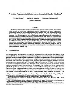
QoS routing objectives are discussed in [12, 13] and implications with common-practize load-balancing solutions are addressed in [14]. In addition to spatial, temporal characteristics are included in path selection in [15–17]. The problem of mapping cores onto NoC architectures and routing communication is addressed in [5, 8, 18–21]. In all works, the mapping and routing is functionally decomposed into modules on the basis of a flowchart, as depicted in Figure 1. The order in time in which processing is expected to take place is used in making the decomposition into modules. Each module has its separate constraints and optimization goals. In [8, 18–21], mapping is perceived as a special case of the NP-complete quadratic assignment problem (QAP) [22]. Intuitively, the QAP can be described as the problem of assigning a set of cores to a set of locations with given distances between the locations and given weights of the communication between the cores. The goal is then to map the cores onto locations in such a way that the sum of the products between communication weights and distances is minimal. Due to the intractability of the QAP, all works use suboptimal approximation methods that iteratively evaluate potential solutions as indicated by the iteration arrow in Figure 1. 1
The scope of this work is the TDM-based Æthereal NoC but the concept is more widely applicable [10, 11].
Iteration Map core ports
Spatially route communication
Temporally route communication
Figure 1: Mapping followed by routing with iteration.
The solution space traversal method used to solve the QAP in [8, 18] is a restricted branch-and-bound [22] algorithm. The algorithm maps cores onto a tile-based architecture, aiming to minimize energy while throughput constraints are satisfied. The latter is accomplished by making the distance parameter in the QAP model the energy consumed when transporting bits from one location to the other. Static xy routing is used in [18]. In [8] the algorithm is extended to route with the objective to balance network load. In [19–21] a heuristic improvement method is used. An initial mapping is derived with objectives such as minimizing communication delay, area or power dissipation. This is succeeded by routing according to a predefined routing function. Routing and evaluation is repeated for pair-wise swaps of nodes in the topology, thereby exploring the design space in search for an efficient mapping. In [21] the algorithm is extended to integrate physical planning and the design space exploration is improved with robust tabu search. In all presented iterative algorithms [8, 18–21], optimality refers to a cost function that evaluates the routes produced by the routing algorithm on a given mapping. Mapping decisions therefore anticipate and rely on the abilities of the routing algorithm to find optimal (and deadlock-free) routes between the locations decided by the mapping algorithm. Known mapping and routing algorithms that incorporate QoS guarantees [15, 16, 21] either assume static communication flows [15, 16], where message injection times are known at design time, or do not derive any analytical bounds on throughput and latency [21]. TDM-based NoC architectures are presented in [5, 10, 11]. However, only [5] address the resource allocation on such architectures. A greedy noniterative algorithm first maps cores based on clustering whereafter communication is routed by static xy routing. Finally, temporal routing allocates TDM time-slots on the network channels such that QoS is guaranteed. This waterfall approach divides the allocation in three distinct phases with no coupling or feedback. While having a low run-time, this methodology pushes responsibility forward where it can be costly or even impossible to undo mistakes from earlier phases. Aforementioned works address only regular topologies and use routing algorithms that are restricted to such topologies, for example, dimension-ordered routing [23], northlast [24], odd-even [25], and DyAD [26]. However, algorithms supporting irregular topologies are scarce. Benini [27] outline a design flow for application specific NoCs using a turn-prohibition algorithm that supports irregular topologies [28]. No details are however given as to how turns are selected or how path finding is done on the prohibited network.
Andreas Hansson et al. This work, being an extension of [29], unifies the three resource allocation phases: spatial mapping of cores, spatial routing of communication, and the restricted form of temporal mapping that assigns time-slots to these routes. The hierarchically decomposed model, depicted in Figure 2, is fundamentally different from [5, 8, 18–21] in that mapping is no longer done prior to routing but instead during it. The main goal of our methodology is to enable efficient application-specific NoCs for both best-effort and guaranteed service traffic, thus extending and elaborating on the methodology proposed in [29]. The key ideas and contributions of UMARS+ that allow us to achieve this goal are:
3 For every intercore communication, map source and destination by spatially routing and temporally routing the communication
Figure 2: Mapping coupled with routing, hierarchically decomposed.
fc . . .
(i) mapping is transformed into a path selection problem, (ii) temporal load (TDM slot tables) is included in the path selection objective function, (iii) differentiation is made between best-effort and guaranteed service traffic, (iv) deadlock is avoided by adaptive turn-prohibition, enabling efficient use of residual resources on any network topology. 3.
fc . . .
Controller ···
pck
Header parsing unit
GS pck BE
.. . pck
BACKGROUND
Switch Header parsing unit
.. .
GS pck BE
3.1. Application We assume that the application is mapped onto cores using existing tools such as [30]. The cores are computational and storage elements of the SoC, such as processors, coprocessors, DSPs, hardware accelerators, memory blocks, I/O blocks. Communication between cores is characterised as flows, or sequences of packets, from a source to a destination port. We distinguish between guaranteed and best-effort services. Guaranteed services (GS) are used for real-time critical traffic and best-effort (BE) for noncritical traffic. Despite the name, even the BE traffic enjoys a number of qualitative QoS attributes [31], namely: (i) data integrity, meaning that data is delivered uncorrupted; (ii) loss-less delivery, which means no data is dropped in the network; (iii) in-order delivery, guaranteeing that data arrive at the destination in the order it was sent by the source. BE services are typically designed for average-case scenarios and require no resource reservations. As a consequence, BE services use resources efficiently. The main disadvantage of BE services is the unpredictability regarding arrival times. In the best case, if sufficient boundary conditions are assumed, a statistical performance bound can be derived [32]. GS adds flow isolation to the list of qualitative QoS attributes. Thus the network protects each flow against other (malicious) flows. Moreover, GS introduce a number of quantitative QoS attributes, incurring time-related bounds on throughput and latency. To deliver those quantitative guarantees, traffic characteristics must be known in advance [33]. Minimum throughput and maximum latency con-
Figure 3: Router architecture where every unidirectional physical channel is shared by two virtual channels, one for guaranteed service (GS) and one for best-effort (BE).
straints of the application flows are therefore determined beforehand by means of static analysis or simulation. 3.2.
Network
The Æthereal network comprises interconnected routers and network interfaces (NI). The topology can be regular, such as a mesh, torus, hypercube, or Clos. Irregular topologies are also supported to enable dedicated solutions [27, 34–36]. NIs provide communication services to the cores at the level of the transport layer in the OSI reference model [6]. This is the first layer that offers end-to-end services, hiding the network details [1]. The physical, data-link and network layers of the protocol stack, all being network specific, are thereby not visible to the cores. The NI does not implement any switching functionality. As a consequence, a flow control digit, or flit, destined for a different port on the same NI must turn around in the router network. The task of a router is to forward data flows from source port to destination port, solving contention when necessary. The architecture, shown in Figure 3, uses wormhole routing [37]. No routing decisions are taken by the routers as we employ source routing. The NIs contain programmable registers that associate every flow with a path. Upon flit injection, the source NI encodes the path in the header flit and the routers merely execute the decisions already taken.
4
VLSI Design Application
Topology synthesis
Constraints
Cores
UMARS+
Smallest mesh loop
RTL synthesis and backend
SystemC/RTL simulation
NoC hardware and software
Performance verification
Buffer sizing
Figure 4: A top-level view of the complete proposed flow.
Two virtual channels [37], one guaranteed service channel and one best-effort channel, share each physical channel. By dissociating the buffers from the actual physical channels, a blocked packet in one virtual channel does not block packets residing on other virtual channels [38]. This mechanism affords a division of the entire physical network into two disjoint logical networks [39, 40]. The logically isolated networks use different policies for communication management and can be treated as conceptually separated entities. The arbitration mechanism that multiplexes between the virtual channels is based on a two-level arbitration scheme. The first level gives priority to GS flows. These flows are thereby isolated from all BE flows as blocking in the BE network can never violate given guarantees. In the second level, two different schemes are used for BE and GS flows, respectively.
channel to carry several flows. By controlling channel arbitration through a TDM slot table in such a way that two flows never compete for the same time-slot, contention-free routing is achieved. In other words, once a flit is injected in the router network it never waits for another flit. The slot table is also used to divide bandwidth between the different flows. Note that deadlock is not possible for GS flits as contention is resolved at design-time. 3.3.
Our problem is to (1) map the application cores onto any given NoC topology, (2) statically route the communication flows, and (3) allocate TDM time-slots on network channels so that application constraints are met.
3.2.1. Best-effort arbitration Best-effort flows require contention resolution on the granularity of flits, as multiple packets can request the same output channel and flit arrival cannot be predicted. This contention is resolved individually in each router using a nonoptimal iSlip [41] algorithm (round-robin switch-matrix scheduling). The dynamic contention resolution leads to unpredictable storage requirements and delays. Moreover, if a flit is blocked due to busy resources all the trailing flits of that packet are also halted, thereby blocking the resources they occupy in terms of channels and buffers. This can result in chained blocking [42] where the resources of a blocked packet again causes other packets to block, a property that makes wormhole routing very susceptible to deadlock [37, 43]. We address deadlock by means of avoidance, the prominent strategy in NoCs [3, 5, 8, 35, 44]. (Progressive [10, 45] and regressive [46] deadlock recovery techniques exist but are relatively uncommon.) Avoidance-based deadlock-free routing relies on restrictions on resource allocation [37, 43]. In contrast to [35], that advocates the use of virtual channels, we do not add any hardware but solely restrict the BE routing.
Problem description
Two important requirements can be identified and the onus is, in both cases, on the mapping and routing phases. First, the constraints of individual flows must be satisfied. These constraints must hence be reflected in the selection of mapping, path and time slots such that proper resources are reserved. Second, all flows must fit within the available network resources without causing deadlock. Failure in allocating a flow is attributable to nonoptimal previous allocations or insufficient amounts of network resources. This calls for conservation of the finite pool of resources, namely the channels and their time-slots. This work shows how path selection can be extended to span also mapping and time-slot allocation. This enables the aforementioned requirements to be formulated as path selection constraints and optimization goals. Figure 4 shows the top-level NoC design flow [5] and the role of UMARS+ in the generation of the NoC hardware and software. The end result is a SystemC model and synthesisable RTL VHDL, compliant with the NXP back-end flow. 4. 4.1.
PROBLEM FORMULATION Application
3.2.2. Guaranteed service arbitration The services are given by the set of valid service classes. Guarantees are implemented by solving contention on the flow level, using TDM-based virtual circuits. Every channel in the network is multiplexed in time, thereby enabling a single
Definition 1. The set of valid service classes Q = {GS, BE} represents guaranteed and best-effort service, respectively.
Andreas Hansson et al. Both service classes provide data-integrity, loss-less delivery and in-order delivery. GS extend those fundamental services with flow isolation and quantitative guarantees on minimum throughput and maximum latency. The application is characterized by an application graph, comprised of communicating core ports. Definition 2. An application graph is a directed multigraph, A(P, F), where the vertices P represent the set of core ports, and the arcs F represent the set of flows between the ports. The set of flows comprises two mutually exclusive subsets, FGS and FBE , containing GS and BE flows, respectively. More than a single flow is allowed to connect a given pair of ports. Every core port is source or destination of at least one flow, leaving no node isolated. Each flow f ∈ F is associated with a service class, q( f ) ∈ Q, a minimum throughput, b( f ) ∈ R, and a maximum latency constraint, l( f ) ∈ R. Let s( f ) denote the source node of f and let d( f ) denote the destination node.
5 GS 150/400
BE 100/100 Input
Filter 1
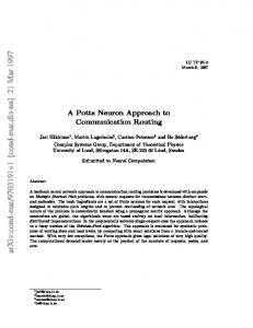
Definition 3. The mapping groups PM , is a partition of P where the elements are jointly exhaustive and mutually exclusive. An example of such a partition on a set of core ports P = { p0 , p1 , p2 } is shown in Figure 7 where PM = {{ p0 , p1 }, { p2 }}. The union of the elements in PM is clearly the entire P, making the partition jointly exhaustive. Moreover, the elements of PM are mutually exclusive as no p ∈ P exists in more than one of them. A partition according to Definition 3 corresponds to an equivalence relation where two elements in P are considered equal if they must be mapped to the same spatial location. The equivalence class of a core p is hereafter denoted by [p]. In the example shown in Figure 7, [p0 ] = [p1 ] = { p0 , p1 } whereas [p2 ] = { p2 }. 4.2. Network Time-division of network channel capacity is governed by slot tables. Definition 4. A slot table is a sequence of elements in F 0 = F ∪ {∅}. Slots are either occupied by a flow f ∈ F or empty, represented by ∅. The number of empty slots in a slot table t is denoted σ(t). The same slot table size ST is used in all the tables of the network.
Mem.
GS 800/200 Filter 2
Output
GS 10/50
BE 100/100
Figure 5: Example application consisting of five core ports and six flows with diverse service requirements. The labels on the edges denote throughput/latency requirements in Mbps and ns, respectively.
�∅, ∅, ∅, ∅, f1 �
c0 t(c0 ) = � f0 , f0 , ∅, ∅, ∅�
An example application, containing five core ports, is shown in Figure 5. The ports are interconnected through six flows with diverse service requirements. Bandwidth measures are given in Mbps by the designer, as described in [5]. These numbers are, in a preprocessing stage, translated into a real number of TDM slots. To be able to constrain mapping according to physical layout requirements (e.g., subsystem grouping), we allow grouping of the core ports in P and map groups instead of individual ports. UMARS+ is thereby forced to map ports in a group to the same spatial location (NI).
GS 400/100
c1 � f1 , f0 , f0 , ∅, ∅�
c2 �∅, f1 , f0 , f0 , ∅�
σ(t(c0 )) = 3
Figure 6: Two flows, f0 and f1 are allocated one and two time-slots, respectively, on the paths indicated by the arrows.
To improve latency and reduce buffering requirements, the virtual circuits are pipelined. Pipelining requires a logical notion of router synchronicity, which is possible in the Æthereal NoC. If a slot i is reserved for a flow f on a channel, then slot i+1 (modulo the table size) must be reserved on the next channel along the path as depicted in Figure 6. NoCs are represented by interconnection network graphs. Definition 5. An interconnection network graph I is a strongly connected directed multigraph, I(N, C). The set of vertices N is composed of three mutually exclusive subsets, NR , NNI and NP containing routers, network interfaces (NI), and core-port mapping nodes as shown in Figure 7. The latter are dummy nodes to allow unmapped core ports to be integrated in the interconnection graph. The number of core-port mapping nodes in I is equal to the number of mapping groups, |NP | = |PM |. The set of arcs C is composed of two mutually exclusive subsets, CR and CP containing physical network channels and dummy mapping channels. Channels in CR represent the physical network architecture and interconnect nodes in NR and NNI . The channels in CP interconnect every node in NP to all nodes in NNI . This construction allows all cores to be mapped to any NI. No direct interconnections are made between nodes in NR and NP . More than a single physical channel is allowed to connect a given pair of routers. However, an NI node nNI is always connected to a single router through exactly one egress channel cE (nNI ) ∈ CR and exactly one ingress channel cI (nNI ) ∈ CR , as depicted in Figure 7.
6
VLSI Design cE
p1
p0
R
P
NI
P
NI
p2
P
NI
P
NI
R
p2
p2
I0
→
I1
→
map0
→
map1
→
�
∅ = P0
�
⊆
P1
··· ···
⊆
cI � f1 , ∅, f0 �
R
NI
p1
p0
cI �∅, ∅, f0 �
NI
P
p1
p0
�∅, ∅, ∅�
NM
� f0 , f1 , f1 �
� f0 , ∅, ∅�
cI
P
cE
cE
�∅, ∅, ∅�
Ik
→
mapk
⊆
···
(a)
→
�
Pk = { p 0 , p 1 , p 2 } = P
(b)
(c)
Figure 7: Successive refinement of mapping and interconnection network.
Each channel c ∈ C has a bandwidth not yet reserved (residual bandwidth) measured in number of slots, β(c) ∈ R, a discretized ditto, β(c) ∈ N, and a slot table, t(c). Let s(c) denote the source node of c and let d(c) denote the destination node.
reserved by a flow, ti ∈ F. If that slot is empty, ti = ∅, then ti� is used instead. As a consequence, a slot on position i in the joined table is empty if and only if both ti and ti� are empty.
4.3. Path selection
Definition 10. An aggregated slot table function t : seq C → seq F 0 maps a sequence of channels �c0 , . . . , ck � to an aggregated slot table,
Definition 6. A path π ∈ seq1 C from source ns ∈ N to destination nd ∈ N is a nonempty sequence of channels �c0 , . . . , ck � such that
With the shift and union operator we can formulate a slot table aggregation function.
� �
��
(1) d(ci ) = s(ci+1 ) for 0 ≤ i ≤ k − 1, (2) s(c0 ) = ns and d(ck ) = nd .
t c 0 , . . . , ck
Definition 7. For a source and destination node ns , nd ∈ N, Π(ns , nd ) is the set of all possible paths from ns to nd . 4.4. Time-slot allocation When allocating time-slots on a given path π = �c0 , . . . , ck �, we first determine the set of available time-slots relative to c0 . To do so we aggregate the individual slot tables through shift and union operations on the slot tables. Definition 8. The left shift operator Li is an unary operator that shifts a slot table i steps cyclically to the left, i ∈ N+ : i
�
�
�
def
L = L1 .
⎧ ⎨ ti
ti = ⎩ � ti
if ti =/ ∅, if ti = ∅.
(3)
Consider, for example, allocating slots on the path �c0 , c1 , c2 � in Figure 6. From the figure we get t(c0 ) = � f0 , f0 , ∅, ∅, ∅�, t(c1 ) = � f1 , f0 , f0 , ∅, ∅� and t(c2 ) = �∅, f1 , f0 , f0 , ∅�. To derive the set of empty slots, we start with the slot table of c0 , t(�c0 �) = t(c0 ) = � f0 , f0 , ∅, ∅, ∅�.
We continue by adding L1 t(c1 ) followed by L2 t(c2 ) and get � �
t �� = �∅, ∅, ∅, ∅, ∅�,
�� ��
� � = f0 , f0 , ∅, ∅, ∅ , �� �� � � t c0 , c1 = f0 , f0 , ∅, ∅, f1 , �� �� � � t c0 , c1 , c2 = f0 , f0 , ∅, ∅, f1 .
t c0
(1)
Definition 9. The union operator | is a binary operator that joins two equally sized slot tables: �t0 , . . . , tk � | �t0� , . . . , tk� � = �t0�� , . . . , tk�� � where ��
� � � � � � = L0 t c 0 L1 t c 1 . . . Lk t c k .
Every channel slot table t(ci ), is shifted cyclically i steps left and thereafter joined by the union operator. A slot in t(�c0 , . . . , ck �) is empty if and only if it is empty in all shifted slot tables [6]. By definition the empty sequence of channels is associated with the empty slot table of size ST .
�
L t0 , . . . , tk = ti+1 , . . . , tk , t0 , . . . , ti ,
��
t �� = �∅, . . . , ∅�,
(2)
Hence, for every position 0 ≤ i ≤ k in the sequence, the item in the left hand side slot table, ti , is preferred if that slot is
(4)
Note that the addition of c2 does not change the aggregated slot table as t(c2 ) is merely t(c1 ) shifted one step to the right. 4.5.
Deadlock avoidance
To guarantee deadlock freedom and at the same time offer maximum routing flexibility we use a turn-prohibition algorithm [28] built on the turn model [47].
Andreas Hansson et al.
7
Definition 11. A turn is an ordered pair of directed channels (ci , c j ), ci = / c j such that d(ci ) = s(c j ). That is, a pair of channels such that ci is entering the node that c j is leaving.
(1) Allocate all flows in FGS (2) Derive the set of permitted turns T + (Ii ) by turn-prohibiting the current network Ii (3) Allocate all flows in FBE
Definition 12. T(I) denotes the set of possible turns between channels in the interconnection network I. Definition 13. T − (I) denotes the set of prohibited turns and T + (I) = T(I) \ T − (I) the set of permitted turns. We introduce a restricted routing function for BE traffic to assert deadlock freedom. This function prohibits any turn not in the set of permitted turns T + (I). The latter is derived by using any cycle-breaking algorithm with support for the topology of the network I. Definition 14. A turn-prohibiting routing function R� is of the form R� : T + (I) × C × N → P (C), where P (C) is the power set of C. That is, when a BE flow destined for nd enters a node through one of its input channels ci , R� (T + (I), ci , nd ) supplies a nonempty set of channels {c1 , c2 , . . . , ck } ⊂ C through which the flow may be routed to its next hop enroute to nd without causing deadlock.
Algorithm 1: Allocation of all flows in F.
4.7.
We introduce a major change from previous work and formulate mapping and path selection problem as a pure path selection problem. Given an interconnection network I0 and an application graph A, we must select a path π for every flow f ∈ F such that throughput (5) and latency (6) requirements of the flow are met (for GS flows), without over-allocating the network channels (7), bandwidth of t(π) ≥ b( f ), latency of t(π) ≤ l( f ), β(c) ≥ 0, ∀c ∈ C.
4.6. Mapping The NIs and core port mapping nodes together form the set of nodes to which the port groups can be mapped.
UMARS+ contribution
(5) (6) (7)
The actual mapping from core ports to mapping nodes is captured by a function.
The theory required to derive worst-case throughput and latency from a slot table is covered in [48]. Note that UMARS+ does not consider physical-level issues such as floorplan congestion and wire length. It does, however, enable the designer to (1) construct any regular or irregular topology as input to the algorithm, (2) group the core ports and thus force them to be mapped to the same NI, and (3) partially (or even fully) specify the core port mapping.
Definition 16. A mapping function, map : PM → NM , maps sets of ports (the elements in PM ) to mappable nodes.
5.
Both the interconnection network I and the mapping function are refined or iterated over. We therefore subscript them with an index. Our starting point is an initial mapping, map0 , where every [p] ∈ PM is mapped to a unique nP ∈ NP . Similarly, I0 denotes the initial network where no channel capacity is reserved, β(c) = β(c) = ST , and all slots in t(c) are empty for every channel c ∈ C. As seen in Figure 7(a), the range of map0 covers only NP . As the algorithm progresses (b), the range of mapi covers both NP and NNI partially. Successive iterations of mapi progressively replace elements of NP with elements of NNI until a final mapping is derived (c), where the range of mapk contains elements of NNI exclusively.
In this section, we present the UMARS+ algorithm. The methodology is described in Sections 5.1 through 5.4. In Section 5.5, we prove algorithm termination, whereafter we conclude in Section 5.6 with a discussion on UMARS+ timecomplexity. The outmost level of UMARS+ is outlined in Algorithm 1 and briefly introduced here. We start by allocating (map and route) all guaranteed-service flows of the application in Step (1). In Step (2), a set of permitted turns is derived using the current interconnection network. Finally, all best-effort flows are allocated in Step (3), just as was done with the guaranteed-service flows. Allocation of FGS and FBE is further explained in Section 5.2.
Definition 17. The set of mapped core ports Pi� = { p ∈ P | mapi ([p]) ∈ NNI } denotes the elements in P which are mapped to NIs in iteration i.
5.1.
Definition 15. The set of mappable nodes, NM = NNI ∪ NP as shown in Figure 7(a) contains all nodes to which the elements of PM can be mapped.
From our definition of map0 it follows that P0� = ∅. Later we show that there exists a mapping mapk with all ports mapped to elements in NNI , hence Pk� = P.
UNIFIED MAPPING AND ROUTING
Turn-prohibition
Turn-prohibition is traditionally based purely on the network topology [8, 24, 27, 34]. The turn-prohibition can then be done prior to the allocation of GS flows and depends only on the NoC topology. Thereby, it implicitly assumes uniform channel capacities. By delaying this step, we can incorporate
8
VLSI Design
�
(1) Let the set of unallocated flows Fi = Fq (2) While Fi� = / ∅: (a) Get flow arg max f ∈F �� b( f ) (b) Select a path π ∈ Π(s( f ), d( f )) � = Fi� \ { f } (c) Fi+1
Algorithm 2: Allocation of a set of flows Fq .
knowledge of residual bandwidth in the prohibition algorithm. After allocating FGS , the residual capacity on the network channels, which is what is available for the flows in FBE , is not uniform. Employing a traditional turn-prohibition algorithm, we risk prohibiting those turns where there is capacity left. We address this by using the algorithm proposed in [28] with b( f ) as channel weight. Besides being applicable to any topology, this algorithm bounds the accumulated prohibited turn weight to 1/2 of the total weight. Hence, by using the nondiscretized residual bandwidth as channel weights we assure that no more than half the residual turn bandwidth is prohibited. 5.2. Allocation of a set of flows Allocation of all flows Fq belonging to a certain service class q is done according to Algorithm 2. A brief explanation follows and we detail it further in Sections 5.3 and 5.4. In Step (2)(a), a flow f is selected based on bandwidth requirements. UMARS+ iterates over the monotonically decreasing set of unallocated flows Fi� and never back-tracks to reevaluate an already allocated flow. This results in low timecomplexity at the expense of optimality. A path π is selected for f in Step (2)(b). By initially mapping cores to the core mapping nodes, connected to all NIs, the first and last channel traversed implicitly determine what NI s( f ) and d( f ) are mapped to, respectively. If q( f ) = GS then time-slots are allocated to f on π. Thereafter, mapi and Ii are updated to reflect the new state. The procedure is repeated until all flows are allocated. 5.3. Flow traversal order We order the flows based on bandwidth requirements, in Step (2)(a) of Algorithm 2, as it (i) helps in reducing bandwidth fragmentation [14], (ii) is important from an energy consumption and resource conservation perspective as the benefits of a shorter path grow with communication demands [8], and (iii) gives precedence to flows with a more limited set of possible paths [8]. Ordering by b( f ) alone may affect resource consumption negatively as communication chains are disregarded. That
is, clusters of interconnected cores are not mapped in sequence. This may increase average hop-count as communicating cores risk being mapped far apart due to resource saturation. For this reason, the selection is limited to flows having s( f ) or d( f ) mapped to a node in NNI . Every cluster of communicating cores then have their flows allocated in sequence. A similar approach is employed in [19, 20], where the next core is selected based on communication to already placed cores. Due to the nature of the least-cost path selection algorithm, explained in Section 5.4.2, we restrain the domain even more and only consider flows where s( f ) ∈ Pi� . This additional restriction can be removed if path selection is done also in the reverse direction, from destination to source, which is not the case in the current implementation. The next flow in Algorithm 2 is chosen according to (8), where f ∈ Fi�� if and only if f ∈ Fi� ∧ s( f ) ∈ Pi� . When the latter condition is not fulfilled by any flow, the entire Fi� is used as the domain, arg max b( f ).
(8)
f ∈F ��
5.4.
Path selection
When a flow f is chosen, we proceed to Step (2)(b) of Algorithm 2 and select a path for f . This is done according to Algorithm 3, briefly presented here, followed by in-depth discussions in Sections 5.4.1 through 5.4.5. Path selection for f is composed of three major tasks. (1) Speculative bandwidth reservations for f are removed from egress and ingress channels in Steps (1) and (2) to have Ii reflect what resources are available to f prior to its allocation. Speculative reservations are required as interdependent flows are not allocated simultaneously and are further discussed in Section 5.4.1. (2) A path from s( f ) to d( f ) is selected in Steps (3) and (5), a procedure elaborated on in Section 5.4.2. If s( f ) or d( f ) are not yet mapped to NIs, these steps include refinement of mapi , which is covered in Section 5.4.4. If mapi is refined, then bandwidth reservations are made on ingress and egress channels for flows other than f , as they now have their source or destination mapped to an NI. (3) If q( f ) = GS, then a set of time-slots is selected. Resources used by f are then reserved on the resulting path π, as discussed in Section 5.4.5. 5.4.1. Bandwidth reservation When s( f ) for a flow f is mapped to an NI, the communication burden placed on the ingress and egress channels of the NI is not determined by f only. As every p in [s( f )] is fixed to this NI, the aggregated communication burden of all flows incident to those cores is placed on the ingress channel. The egress channel similarly has to accommodate all flows emanating from those cores. When d( f ) is mapped, all flows to or from [d( f )] are accounted for accordingly.
Andreas Hansson et al.
9
Failing to address the above may result in overallocation of network resources. Numerous flows, still not allocated, may be forced to use the ingress and egress channel due to an already fixed mapping. An NI may thereby be associated with an implicit load, not accounted for when evaluating possible paths. We make this load explicit by exploiting knowledge of ingress-egress pairs, as in [49].2 We define a function that estimates how much bandwidth (measured in slots) a flow reserves in the network.
⎧ ⎨b( f ) � b ( f ) = ⎩
b( f ) �
if q( f ) = BE if q( f ) = GS.
(9)
5.4.2. Selecting constrained least-cost path Steps (3) and (5) of Algorithm 3 select a constrained leastcost path using Dijkstra’s algorithm. Three modifications are done to the standard relaxation procedure, where π p denotes the partial path from s( f ) to the current node. (1) Best-effort flows must obey the turn-prohibiting routing function R� . Therefore, only channels in R� (T + (Ii ), d(last π p ), d(F)) are evaluated further. We use the turn net approach described in [50], as the original Dijkstra’s algorithm cannot find least-cost paths on a turnprohibited network. (2) The search space is pruned by discarding emanating channels that cannot meet bandwidth constraints. For best-effort flows we discard channels where β(c) < b� ( f ). Guaranteed service flows do a similar control on the discretized residual bandwidth β(c) < b� ( f ) but also prune channels where σ(t(π p ) | Lt(c)) < b� ( f ). Channels that cannot meet bandwidth constraints or 2
The authors suggest selecting paths that interfere least with future requests through a heuristic called minimum interference routing algorithm (MIRA). The algorithm does not only consider the ingress and egress channels but also calculates an interference metric for every intermediate channel in the network.
¯
Although we have no knowledge of exactly what time slots are needed by future guaranteed service flows, we can estimate the bandwidth required by b� ( f ) and incorporate estimated average load in the cost function, further discussed in Section 5.4.3. Steps (1) and (2) of Algorithm 3 restore the speculative reservations for f on egress and ingress channel to have Ii reflect what resources are available prior to its allocation. The corresponding bandwidth reservations on egress and ingress channels are carried out in Steps (4)(b), (4)(c) and Steps (6)(b), (6)(c) for source and destination NI, respectively.
¯
Definition 18. The bandwidth requirement estimation function b� : F → R+ supplies an estimate of required network bandwidth for a flow f as
(1) If s( f ) ∈ Pi� , restore bandwidth reservation on egress channel by adding b( f ) to β(cE (mapi ([s( f )]))) and b� ( f ) to β(cE (mapi ([s( f )]))). (2) If d( f ) ∈ Pi� , restore bandwidth reservation on ingress channel by adding b( f ) to β(cI (mapi ([d( f )]))) and b� ( f ) to β(cI (mapi ([d( f )]))). (3) Select a constrained least-cost path πs from mapi ([s( f )]) to a router nR ∈ NR . (4) If s( f ) ∈ / Pi� , then (a) Refine mapi+1 = mapi ⊕ {[s( f )] →d(head πs )} (b) Reserve egress bandwidth for all unallocated flows b( fE ) emanating from [s( f )] by subtracting f ∈ F E E from β(cE (d(head πs ))) and fE ∈FE b� ( fE ) from β(cE (d(head πs ))) where fE ∈ FE if and only if fE ∈ Fi� , s( fE ) ∈ [s( f )] and fE =/ f (c) Reserve ingress bandwidth for all unallocated flows incident to [s( f )] by subtracting fI ∈FI b( fI ) from β(cI (d(head πs ))) and fI ∈FI b� ( fI ) from β(cI (d(head πs ))) where fI ∈ FI if and only if fI ∈ Fi� and d( fI ) ∈ [s( f )]. (5) Select a constrained least-cost path πd from d(last πs ) to mapi ([d( f )]) (6) If d( f ) ∈ / Pi� , then (a) Refine mapi+1 = mapi ⊕ {[d( f )] →s(last πd )} (b) Reserve egress bandwidth for all unallocated flows emanating from [d( f )] by subtracting fE ∈FE b( fE ) from β(cE (s(last πd ))) and fE ∈FE b� ( fE ) from β(cE (s(last πd ))) where fE ∈ FE if and only if fE ∈ Fi� and s( fE ) ∈ [d( f )] (c) Reserve ingress bandwidth for all flows incident to [d( f )] by subtracting fI ∈FI b( fI ) from β(cI (s(last πd ))) and fI ∈FI b� ( fI ) from β(cI (s(last πd ))) where fI ∈ FI if and only if fI ∈ Fi� , / f. d( fI ) ∈ [d( f )] and fI = (7) If q( f ) = GS, then select a constrained set of slots TS in t(π) for the complete path π = πs � πd and update t(c), for all c ∈ π. (8) Do a final bandwidth reservation by subtracting b( f ) from β(c), for all c ∈ π. If q( f ) = GS then subtract |TS | from β, for all c ∈ π correspondingly.
Algorithm 3: Path selection for a given f .
do not have enough free slots, given t(π p ), are thereby omitted. (3) As the final path must contain only physical network resources, channels in CP may only be the first or last element of a path. Hence, if d(last π p ) ∈ NP , then all channels emanating from d(last π p ) are discarded. The NI architecture requires a path to incorporate at least one physical channel c ∈ CR as flows cannot turn around inside an NI. If a flow has both source and destination mapped to the same NI we must hence traverse the egress channel, turn around in the router and return to the NI through the ingress channel. From a least-cost perspective the best path from an NI to itself is the empty path and we force the algorithm into leaving the NI by doing path selection in
10 two steps. (An alternative with a higher time complexity is A∗ Prune [51] that enables both this constraint and the turnprohibitions to be formulated as path constraints.) The first part of the path πs is selected in Step (3) of Algorithm 3. We know by the definition of I that it is possible to find a path to a router from s( f ) and stop at the one with the lowest cost. If several routers share the same path cost, then we pick the one with highest arity. This heuristic maximises routing flexibility throughout the entire allocation procedure. It also makes sure the source node of the first flow (the one with highest communication volume) is mapped to the NI connected to the router with highest arity, a strategy suggested in [20]. The second part of the path πd is selected in Step (5), starting where πs ended. From there we continue to the location where d( f ) is currently mapped. The complete path is then just the two parts concatenated, π = πs � πd . Deriving π like suggested above may, without further care, lead to a path which is not the least-cost path in Π(s( f ), d( f )) as minimization is done on the parts in isolation.3 However, if a flow f has s( f ) ∈ Pi� , then there is only one possible least-cost router. This follows from every NI being connected to exactly one router and all channel costs being non-negative. Hence, there is only one possible πs and as this πs is a part of any path in Π(s( f ), d( f )) and πd is a leastcost path, π is a least-cost path in Π(s( f ), d( f )). To mitigate the effect of partial minimization, we prefer allocating flows where s( f ) ∈ Pi� , as discussed in Section 5.3. 5.4.3. Choice of cost function The cost function used plays an essential role in meeting the requirements introduced in Section 1. It should hence reflect resource availability and resource utilization. A good heuristic to maximise the probability of successful flow allocation is to select a path with low contention. At the same time we must keep the path length short not to consume unnecessarily many resources. Similar heuristics are suggested in [13, 52, 53]. Double objective path optimization in general is an intractable problem [12]. Combining objectives in one cost function allows for tractable algorithms at the cost of optimality. We therefore argue for a linear combination of the two cost measures, where two constants Γc and Γh control the importance (and normalisation) of contention and hopcount, respectively. Contention is traditionally incorporated by making channel cost inversely proportional to residual bandwidth. Although proved to produce good results in many applications [13, 53], this cost measure has two major drawbacks. First, as the value always is greater than zero its contribution to total path cost grows with distance even if there is no contention on the channels traversed. Second, contention cost grows exponentially, thereby disturbing the balance between contention and hop-count importance. We desire control 3
Compare a sum of minima to the minimum of a sum.
VLSI Design
�∅, ∅, f2 �
� f1 , ∅, ∅�
� f0 , f0 , f1 �
�∅, f0 , f0 �
Figure 8: Scenario where average load is insufficient as metric and leads to a path on which slot allocation invariably fails.
over the relative importance of contention and hop-count through Γc and Γh and therefore use (10) to determine channel cost when allocating a flow with q( f ) = BE. The contention measure, ST − β(c), makes the cost contribution proportional to the occupied bandwidth. It is zero for an unoccupied channel and grows linearly as bandwidth is reserved, �
�
Γc ST − β(c) + Γh .
(10)
When allocating guaranteed service flows, the cost measure in (10) fails to reflect a number of important aspects involved in deciding what is an optimal path. (i) Using only average load when determining contention cost ignores the temporal alignment of the available capacity. Not only must the slots be free, we also require them to be aligned properly to be usable, about which more presently. (ii) It bases the cost on nondiscretized residual bandwidth, thereby looking at the actual bandwidth available without accounting for TDM discretisation artifacts. When using pipelined virtual circuits [6], average load is not reflecting what resources are available to the current flow. Not even the slot table t(c) itself provides an accurate view. The set of available slots for a flow, f , on a channel, c, is a function of the slot tables of all channels preceding c in the path traversed from the location where s( f ) is mapped to the channel c itself. Consider the example in Figure 8 where a flow f2 arrives a router already used by flows f0 and f1 . If we look only at residual bandwidth, f2 prefers the channel going east over the one heading south. However, if we consider not only the number of free slots but also their temporal alignment, south is actually a better choice than east. Even though the filling of the slot table is higher for the south-going channel, the alignment compared to the input channel makes it a better choice.
Andreas Hansson et al.
11
We exploit knowledge of the partial path π p traversed so far and determine contention cost for a channel c by how much t(c) reduces the amount of available slots compared to t(π p ) if c is traversed. Discretized available bandwidth is incorporated by taking the maximum of the two as contention measure, according to (11).
��
Γc max ST − β(c), σ t π p
��
�� � �� − σ t π p | Lt(c) + Γh .
(11) Channels in CP must not contribute to the path cost, as they are not physical interconnect components. We therefore make them zero-cost channels.
5.6.
Algorithm complexity
Due to the greedy nature of UMARS+, time-complexity is very low as seen in (12), where d denotes the maximum degree of any node in N. The expression is dominated by the first term that is attributable to Dijkstra’s algorithm, used for path selection. The second term stems from the turn prohibition and varies depending on the choice of algorithm. Finally, the last term covers the selection of next flow, bandwidth reservations and slot allocation. Experiments indicate that UMARS+ run-time is only 20% higher than that of loadbalancing path selection alone, �
�
��
�
�
�
�
��
O |F | |C | + |N | log |N | +O |N |2 d +O |F | |F |+ |P |+ST . (12)
5.4.4. Refining mapping function 6. When a path πs is selected for a flow f , we check in Step (4)(a) of Algorithm 3, whether s( f ) is not yet mapped to an NI. If not, πs decides the NI to which the core is to be mapped. We therefore refine the current mapping function with the newly determined mapping to a node in NNI as seen in Step (6)(a). This refinement is fixed and every core in [s( f )] is now in Pi� . Correspondingly, we check if d( f ) is not yet mapped to an NI in Step (6) and if not, refine the mapping according to πd in Step (6)(a).
EXPERIMENTAL RESULTS
To evaluate the performance of our methodology, we apply it to a range of SoC designs. The MPEG use-case is a MPEG codec SoC, further described in Section 6.3. The uniform use-case features distributed communication with 24 cores. Each core has a randomly selected set of inter-connected peers with a total aggregated bandwidth of 750 Mbps. The remaining use-cases are internal set-top box designs, each having hot-spots around a limited set of SDRAM ports and 100 to 250 connections. These connections deliver a total bandwidth of 1-2 Gbps to 75 ports distributed across 25 IP modules.
5.4.5. Resource reservation When the entire path π is determined, we perform a slot allocation in Step (7) of Algorithm 3 if the flow requires guaranteed services. The slots available to f are deduced by looking at t(π). From the empty slots we select a set of slots TS such that bandwidth and latency requirements of f are met [48]. All channels c ∈ π are then updated with a new t(c) to reflect what slots are reserved to f . Step (8) ends the procedure by removing the resources reserved for f from β(c) and β(c) for all channels in the path. 5.5. Algorithm termination With each refinement of mapi , zero, one or two additional sets of cores are moved to elements of NNI from NP , hence � ⊇ Pi� , as depicted in Figure 7. Pi+1 Theorem 1. (∃k)Pk� = P: there exists a k such that all core ports are mapped to NIs. Proof. When a flow is f allocated, mapi is refined in Steps (4)(a) and (6)(a) of Algorithm 2 so that s( f ) and d( f ) are guaranteed to be in Pi� . For every allocated flow f ∈ / Fi� we � hence know that s( f ), d( f ) ∈ Pi . � ⊂ Fi� , From Step (2)(c) of Algorithm 2 we know that Fi+1 that is, the set of unallocated flows, monotonically decreases. Hence, ∃k such that all flows are allocated, Fk� = ∅. We know that, for this k, s( f ) and d( f ), for all f ∈ F are in Pk� . As no isolated cores are allowed in A it follows that P = Pk� .
6.1.
Deadlock avoidance
The turn-prohibition algorithm’s ability to preserve residual resources is evaluated by allocating the uniform benchmark to a fixed 3 × 4 mesh with a varying degree of BE and GS flows. We study the relative success rate compared to what is achievable without routing restrictions, that is, when deadlock can occur. The results of three different turn-prohibition algorithms are compared. First, xy routing, second, traditional oblivious turn prohibition not taking residual bandwidth into account, and third, the adaptive turn prohibition that we propose. In Figure 9, we see that the adaptive algorithm consistently outperforms the other two algorithms with a relative success rate constantly above 92%. While the oblivious turnprohibition algorithm offers a qualitative advantage over xy routing by being applicable to any topology, the adaptive algorithm adds also a significant quantitative advantage. 6.2.
Evaluation experiments
A cost function where Γc = 1 and Γh = 1 is used throughout the experiments. Those values favour contention-balancing over hop-count as the slot table size is an order of magnitude larger than network diameter in all use-cases. All results are compared with the traditional multistep algorithm in [5], referred to as waterfall. Only mesh topologies are evaluated, as the aforementioned algorithm is limited to this class of networks. For a given slot table size ST , all
VLSI Design
Relative success rate (%)
12 100
latter makes it more difficult to find a working configuration and stresses the importance of objective unification in all three allocation phases.
95 90 85
6.2.1. Analytic benchmarks
80 75
10/90
30/70
50/50
70/30
90/10
GS/BE mix (%) xy routing Oblivious turn-prohibition Adaptive turn-prohibition
Figure 9: Relative success rate for the different turn-prohibition algorithms.
8 7
Area (mm2 )
6 5 4 3 2
Silicon area requirements are based on the model presented in [54], assuming a 0.13 μm CMOS process. Figure 10 shows that area requirements can be significantly reduced. Up to 33% in total area reduction is observed for the experiment applications. Slot table sizes are reduced in all use-cases, leading to lower buffer requirements, analytically derived as described in [5]. Area savings up to 31% are observed for the NIs but the s1m2p2 use-case is hardly improved at all, showing only a 0.5% decrease. However, the router network is consistently smaller, with an area decrease between 30% and 75%. The distribution of improvement on analytical worstcase latency is shown in Figure 11(a). For every flow the worst-case latency is derived using the model in [5]. The latency achieved using UMARS+ and waterfall are compared on a flow basis and the distribution of these improvement figures are plotted in the diagram. Although a few flows suffer from latency increase (negative improvement) in the s8m1p2 and s8m2p2 use-cases, the majority of flows have significant improvements on worst-case latency. In the MPEG example, every single flow has its worst-case latency reduced by 50% or more.
1 0
6.2.2. Simulation benchmarks MPEG uniform s1m1p2 s1m2p2 s8m1p2 s8m2p2
Network interfaces, waterfall Network interfaces, UMARS+ Routers, waterfall Routers, UMARS+
Figure 10: Comparison of area requirements.
unique n × m router networks with less than 25 routers were generated in increasing order of size. For every such router network, one, two, or three NIs were attached to each router until all application flows were allocated, or allocation failed. Slot table size was incremented until allocation was successful. The run time of UMARS+ is in the order of a few milliseconds on a Linux workstation and the whole topology exploration loop finishes in a matter of seconds for the example SoC designs. Each design is simulated during 3 × 10⁶ clock cycles in a flit-accurate SystemC simulator of the Æthereal NoC, using traffic generators to mimic core behaviour. All the presented use-cases feature applications with guaranteed service flows only. These flows use all three parts of the algorithm (mapping, routing, and slot allocation) and have more allocation constraints than best-effort flows. The
Relative energy consumption of the router network (without NIs), calculated according to the model in [55] is depicted in Figure 12. As the application remains the same and hence essentially the same bits are being communicated, the savings in energy consumption are attributable to flows being allocated on paths with fewer hops. The correlation between energy saving ratio and relative reduction in number of routers is clearly visible. However, as the smaller router network is used more extensively, energy is reduced less than the number of routers. Figure 13 shows the average utilization of channels emanating from NIs and routers, respectively. As expected, utilization increases as router network size is reduced and UMARS+ consequently improves both NI and router utilization. Time-division-multiplexed circuits imply bandwidth discretisation, leading to inevitable over-allocation and complicating the task of achieving high utilization. This together with unbalanced hot-spot traffic, leaving some parts of the network lightly loaded and others congested, lead to inherent low utilization in some of the example use-cases. Note that utilization is only to be optimized after all constraints are met. The distribution of improvement on average and maximum latency is shown in Figures 11(b) and 11(c), respectively. As with the analytical latency comparison we see that a few flows face an increased latency. The bias towards latency improvement is clear though, and in all nonsynthetic
Andreas Hansson et al.
13 100
80 60 40 20
80 60 40 20 0
0
MPEGuniform s1m1p2 s1m2p2 s8m1p2 s8m2p2
< −50% < −25% < 0%
100 Improvement distribution
Improvement distribution
Improvement distribution
100
MPEG uniform s1m1p2 s1m2p2 s8m1p2 s8m2p2
< −50% < −25% < 0%
< 25% < 50% ≥ 50%
(a) Analytical worst-case delay
80 60 40 20 0
MPEG uniform s1m1p2s1m2p2 s8m1p2s8m2p2
< 25% < 50% ≥ 50%
< −50% < −25% < 0%
(b) Average delay in simulation
< 25% < 50% ≥ 50%
(c) Maximum delay in simulation
0.7
80
0.6
70 60
0.5
Utilization (%)
UMARS/waterfall ratio
Figure 11: Distribution of improvement on flow network delay. For every flow, latency of UMARS+, lUMARS+ , is compared to that of waterfall, lwaterfall , as 1 − lUMARS+ /lwaterfall . These improvement measures are divided into bins of 25% width whereafter the relative frequency of the bins is plotted on a per application basis.
0.4 0.3 0.2
40 30 20
0.1 0
50
10 MPEG uniform s1m1p2 s1m2p2 s8m1p2 s8m2p2
0
Energy consumption Number of routers
MPEG uniform s1m1p2 s1m2p2 s8m1p2 s8m2p2
Network interfaces, waterfall Network interfaces, UMARS+ Routers, waterfall Routers, UMARS+
Figure 12: Comparison of energy consumption.
Figure 13: Comparison of NoC resource utilization.
use-cases the latency is reduced with 50% or more for more than half of the flows.
Table 1: Comparison of MPEG NoCs. Generation Mesh Slots
6.3. An MPEG application An existing MPEG codec SoC with 16 cores constitutes our design example and results are shown in Table 1. The architecture uses a single external SDRAM with three ports to implement all communication between cores. A total of 42 flows tie the cores together. Using the design flow presented in [5]4 results in a 2 × 3 mesh, referred to as clustering in Table 1, with a total estimated area of 2.35 mm2 . For comparison, a naive mapping with one core partition per NI is 4
Clustered mapping, xy routing and greedy slot allocation.
Clustering Naive Optimized UMARS+
NI Router area area
2 × 3 128 1.83 3 × 6 128 2.17 1×3 8 1.51 1×3 8 1.26
0.51 2.32 0.35 0.32
Total area
Area diff
Avg wc latency
2.35 ref 1570 ns 4.49 +91% 1583 ns 1.86 −21% 399 ns 1.57 −33% 383 ns
almost double in size, whereas the worst-case write latency remains more or less unaffected. A manually optimized mapping was produced which managed to reduce the network area with 21% and an almost four-fold reduction of average worst-case write latency was observed [5].
14
VLSI Design
UMARS+ arrives at a mesh of equal size to what was achieved using the manually optimized mapping. Fewer NIs are needed leading to reductions in router area. Smaller buffer requirements, attributable to less bursty time-slot allocation, results in reduced NI area. Total NoC area is reduced by 17% and average worst-case latency by 4% compared to the optimized handcrafted design. The solution was achieved in less than 100 milliseconds on a Linux workstation. Only a 20% increase in run-time was observed when compared to a pure load-balancing path selection, without mapping and slot allocation. 7.
CONCLUSION AND FUTURE WORK
We conclude this work by summarizing our contributions in Section 7.1 and finally presenting directions for future work in Section 7.2. 7.1. Contributions In this paper, we consider the problem of mapping cores onto any given NoC topology and statically route the communication between these cores. We present the UMARS+ algorithm which integrates the three resource allocation phases: spatial mapping of cores, spatial routing of communication and TDM time-slot assignment. As the main contribution we show how mapping can be fully incorporated in path selection. This allows for formulation of a single consistent objective function that is used throughout all allocation phases. The objective is reflecting two important goals, namely, fulfilment of application constraints and conservation of network resources while guaranteeing deadlock freedom. We show how the pruning and the cost metric used in path selection can be extended beyond one channel to capture the nature of virtual circuits. By incorporating also the traversed path in cost calculations we derive a metric that reflects how suitable a channel is when used after the channels already traversed. We show how a highly flexible turn-prohibition algorithm can be used to provide maximum adaptiveness in routing of best-effort flows. The proposed algorithm bases the prohibitions on residual resources such that best-effort flows can use what is not required by guaranteed-service flows. The time-complexity of UMARS+ is low and experimental results indicate a run-time only 20% higher than that of path selection alone. We apply the algorithm to an MPEG decoder SoC, improving area 33%, power dissipation 35% and worst-case latency by a factor four over a traditional waterfall approach. 7.2. Future work We compare UMARS+ only to [5], and a more extensive comparison with traditional algorithms [8, 18–21] is of value. To allow a more extensive design space exploration for both mapping and routing, UMARS+ can be extended to a k-path algorithm, enabling a trade-off between complexity
and optimality. This extension can also be used for traffic splitting, spatially distributing the load of guaranteed service flows over multiple paths. UMARS+ fully supports any topology, thereby enabling application-specific NoC generation. To exploit those capabilities, a valuable extension is to incorporate the algorithm into a more refined topology generation tool. Topologies can then be tailored for an application and physical layout. REFERENCES [1] L. Benini and G. de Micheli, “Networks on chips: a new SoC paradigm,” Computer, vol. 35, no. 1, pp. 70–78, 2002. [2] M. Sgroi, M. Sheets, A. Mihal, et al., “Addressing the systemon-a-chip interconnect woes through communication-based design,” in Proceedings of the 38th Design Automation Conference (DAC ’01), pp. 667–672, Las Vegas, Nev, USA, June 2001. [3] D. Bertozzi, A. Jalabert, S. Murali, et al., “NoC synthesis flow for customized domain specific multiprocessor systems-onchip,” IEEE Transactions on Parallel and Distributed Systems, vol. 16, no. 2, pp. 113–129, 2005. [4] W. J. Dally and B. Towles, “Route packets, not wires: on-chip interconnection networks,” in Proceedings of the 38th Design Automation Conference (DAC ’01), pp. 684–689, Las Vegas, Nev, USA, June 2001. [5] K. Goossens, J. Dielissen, O. P. Gangwal, S. Gonz`alez Pestana, A. R˘adulescu, and E. Rijpkema, “A design flow for applicationspecific networks on chip with guaranteed performance to accelerate SOC design and verification,” in Proceedings of Design, Automation and Test in Europe Conference and Exposition (DATE ’05), pp. 1182–1187, Munich, Germany, March 2005. [6] E. Rijpkema, K. Goossens, A. R˘adulescu, et al., “Trade-offs in the design of a router with both guaranteed and best-effort services for networks on chip,” IEE Proceedings: Computers and Digital Techniques, vol. 150, no. 5, pp. 294–302, 2003. [7] K. Keutzer, S. Malik, J. M. Rabaey, and A. SangiovanniVincentelli, “System-level design: orthogonalization of concerns and platform-based design,” IEEE Transactions on Computer-Aided Design of Integrated Circuits and Systems, vol. 19, no. 12, pp. 1523–1543, 2000. [8] J. Hu and R. Marculescu, “Exploiting the routing flexibility for energy/performance aware mapping of regular NoC architectures,” in Proceedings of Design, Automation and Test in Europe Conference and Exposition (DATE ’03), pp. 688–693, Munich, Germany, March 2003. [9] U. Y. Ogras, J. Hu, and R. Marculescu, “Key research problems in NoC design: a holistic perspective,” in Proceedings of International Conference on Hardware/Software Codesign and System Synthesis (CODES+ISSS ’05), pp. 69–74, Jersey City, NJ, USA, September 2005. [10] M. Millberg, E. Nilsson, R. Thid, and A. Jantsch, “Guaranteed bandwidth using looped containers in temporally disjoint networks within the Nostrum network on chip,” in Proceedings of Design, Automation and Test in Europe Conference and Exhibition (DATE ’04), vol. 2, pp. 890–895, Paris, France, February 2004. [11] A. Laffely, J. Liang, R. Tessier, and W. Burleson, “Adaptive system on a chip (aSoC): a backbone for power-aware signal processing cores,” in Proceedings of International Conference on Image Processing (ICIP ’03), vol. 3, pp. 105–108, Barcelona, Spain, September 2003.
Andreas Hansson et al. [12] R. A. Guerin, A. Orda, and D. Williams, “QoS routing mechanisms and OSPF extensions,” in Proceedings of the IEEE Global Telecommunications Conference (GLOBECOM ’97), vol. 3, pp. 1903–1908, Phoenix, Ariz, USA, November 1997. [13] R. Widyono, “The design and evaluation of routing algorithms for real-time channels,” Tech. Rep. TR-94-024, International Computer Science Institute & University of California, Berkeley, Calif, USA, June 1994. [14] I. Matta and A. Bestavros, “A load profiling approach to routing guaranteed bandwidth flows,” in Proceedings of the 17th Annual Joint Conference of the IEEE Computer and Communications Societies (INFOCOM ’98), vol. 3, pp. 1014–1021, San Francisco, Calif, USA, March-April 1998. [15] R. A. Guerin and A. Orda, “Networks with advance reservations: the routing perspective,” in Proceedings of the 19th Annual Joint Conference of the IEEE Computer and Communications Societies (INFOCOM ’00), vol. 1, pp. 118–127, Tel Aviv, Israel, March 2000. [16] W. H. Ho and T. M. Pinkston, “A methodology for designing efficient on-chip interconnects on well-behaved communication patterns,” in Proceedings of the 9th International Symposium on High-Performance Computer Architecture (HPCA ’03), pp. 377–388, Anaheim, Calif, USA, February 2003. [17] S. Stuijk, T. Basten, M. Geilen, A. H. Ghamarian, and B. Theelen, “Resource-efficient routing and scheduling of timeconstrained network-on-chip communication,” in Proceedings of the 9th EUROMICRO Conference on Digital System Design: Architectures, Methods and Tools (DSD ’06), pp. 45–52, Dubrovnik, Croatia, August-September 2006. [18] J. Hu and R. Marculescu, “Energy-aware mapping for tilebased NoC architectures under performance constraints,” in Proceedings of the Asia and South Pacific Design Automation Conference (ASP-DAC ’03), pp. 233–239, Kitakyushu, Japan, January 2003. [19] S. Murali and G. de Micheli, “Bandwidth-constrained mapping of cores onto NoC architectures,” in Proceedings of Design, Automation and Test in Europe Conference and Exposition (DATE ’04), vol. 2, pp. 896–901, Paris, France, February 2004. [20] S. Murali and G. de Micheli, “SUNMAP: a tool for automatic topology selection and generation for NoCs,” in Proceedings of the 41st Design Automation Conference (DAC ’04), pp. 914– 919, San Diego, Calif, USA, June 2004. [21] S. Murali, L. Benini, and G. de Micheli, “Mapping and physical planning of networks-on-chip architectures with quality-ofservice guarantees,” in Proceedings of the Asia and South Pacific Design Automation Conference (ASP-DAC ’05), vol. 1, pp. 27– 32, Shanghai, China, January 2005. [22] P. M. Pardalos, F. Rendl, and H. Wolkowicz, “The quadratic assignment problem: a survey and recent developments,” in Quadratic Assignment and Related Problems, P. M. Pardalos and H. Wolkowicz, Eds., vol. 16 of DIMACS Series in Discrete Mathematics and Theoretical Computer Science, pp. 1–42, American Mathematical Society, Providence, RI, USA, 1994. [23] L. M. Ni and P. K. McKinley, “A survey of wormhole routing techniques in direct networks,” Computer, vol. 26, no. 2, pp. 62–76, 1993. [24] C. J. Glass and L. M. Ni, “The turn model for adaptive routing,” Journal of the ACM, vol. 41, no. 5, pp. 874–902, 1994. [25] G.-M. Chiu, “The odd-even turn model for adaptive routing,” IEEE Transactions on Parallel and Distributed Systems, vol. 11, no. 7, pp. 729–738, 2000. [26] J. Hu and R. Marculescu, “DyAD: smart routing for networkson-chip,” in Proceedings of the 41st Design Automation Con-
15
[27]
[28]
[29]
[30]
[31]
[32]
[33]
[34]
[35]
[36]
[37]
[38]
[39]
[40]
[41]
ference (DAC ’04), pp. 260–263, San Diego, Calif, USA, June 2004. L. Benini, “Application specific NoC design,” in Proceedings of Design, Automation and Test in Europe Conference and Exposition (DATE ’06), pp. 491–495, Munich, Germany, March 2006. D. Starobinski, M. Karpovsky, and L. A. Zakrevski, “Application of network calculus to general topologies using turnprohibition,” IEEE/ACM Transactions on Networking, vol. 11, no. 3, pp. 411–421, 2003. A. Hansson, K. Goossens, and A. R˘adulescu, “A unified approach to constrained mapping and routing on network-onchip architectures,” in Proceedings of 3rd IEEE/ACM/IFIP International Conference on Hardware/Software Codesign and System Synthesis (CODES+ISSS ’05), pp. 75–80, Jersey City, NJ, USA, September 2005. S. J. Krolikoski, F. Schirrmeister, B. Salefski, J. Rowson, and G. Martin, “Methodology and technology for virtual component driven hardware/software co-design on the system-level,” in Proceedings of IEEE International Symposium on Circuits and Systems (ISCAS ’99), vol. 6, pp. 456–459, Orlando, Fla, USA, May-June 1999. I. Stoica, “Stateless core: a scalable approach for quality of service in the Internet,” Ph.D. dissertation, Department of Electrical and Computer Engineering, Carnegie Mellon University, Pittsburgh, Pa, USA, December 2000, also as Tech. Rep. CMUCS-00-176. H. Zhang, “Service disciplines for guaranteed performance service in packet-switching networks,” Proceedings of the IEEE, vol. 83, no. 10, pp. 1374–1396, 1995. C. M. Aras, J. F. Kurose, D. S. Reeves, and H. Schulzrinne, “Real-time communication in packet-switched networks,” Proceedings of the IEEE, vol. 82, no. 1, pp. 122–139, 1994. U. Y. Ogras and R. Marculescu, “Application-specific networkon-chip architecture customization via long-range link insertion,” in Proceedings of IEEE/ACM International Conference on Computer-Aided Design (ICCAD ’05), pp. 246–253, San Jose, Calif, USA, November 2005. K. Srinivasan and K. S. Chatha, “A low complexity heuristic for design of custom network-on-chip architectures,” in Proceedings of Design, Automation and Test in Europe Conference and Exposition (DATE ’06), pp. 130–135, Munich, Germany, March 2006. J. Xu, W. Wolf, J. Henkel, and S. Chakradhar, “A design methodology for application-specific networks-on-chip,” ACM Transactions on Embedded Computing Systems, vol. 5, no. 2, pp. 263–280, 2006. W. J. Dally and C. L. Seitz, “Deadlock-free message routing in multiprocessor interconnection networks,” IEEE Transactions on Computers, vol. 36, no. 5, pp. 547–553, 1987. P. Mohapatra, “Wormhole routing techniques for directly connected multicomputer systems,” ACM Computing Surveys, vol. 30, no. 3, pp. 374–410, 1998. D. H. Linder and J. C. Harden, “An adaptive and fault tolerant wormhole routing strategy for k-ary n-cubes,” IEEE Transactions on Computers, vol. 40, no. 1, pp. 2–12, 1991. J. Rexford and K. G. Shin, “Support for multiple classes of traffic in multicomputer routers,” in Proceedings of the 1st International Workshop on Parallel Computer Routing and Communication (PCRCW ’94), pp. 116–130, Seattle, Wash, USA, May 1994. N. W. McKeown, “Scheduling algorithms for input-queued cell switches,” Ph.D. dissertation, University of California, Berkeley, Calif, USA, May 1995.
16 [42] W. J. Dally, “Virtual-channel flow control,” IEEE Transactions on Parallel and Distributed Systems, vol. 3, no. 2, pp. 194–205, 1992. [43] E. Fleury and P. Fraigniaud, “A general theory for deadlock avoidance in wormhole-routed networks,” IEEE Transactions on Parallel and Distributed Systems, vol. 9, no. 7, pp. 626–638, 1998. [44] T. Bjerregaard and J. Sparsø, “A router architecture for connection-oriented service guarantees in the MANGO clockless network-on-chip,” in Proceedings of Design, Automation and Test in Europe Conference and Exposition (DATE ’05), vol. 2, pp. 1226–1231, Munich, Germany, March 2005. [45] P. Guerrier, “Un r´eseau d’interconnexion pour syst´emes int´egr´es,” Ph.D. dissertation, Universit´e Paris VI, Paris, France, 2000. [46] I. Saastamoinen, M. Alho, and J. Nurmi, “Buffer implementation for Proteo networks-on-chip,” in Proceedings of IEEE International Symposium on Circuits and Systems (ISCAS ’03), vol. 2, pp. 113–116, Bangkok, Thailand, May 2003. [47] C. J. Glass and L. M. Ni, “The turn model for adaptive routing,” in Proceedings of the 19th International Symposium on Computer Architecture (ISCA ’92), pp. 278–287, Gold Coast, Queensland, Australia, May 1992. [48] O. P. Gangwal, A. R˘adulescu, K. Goossens, S. Gonz`alez Pestana, and E. Rijpkema, “Building predictable systems on chip: an analysis of guaranteed communication in the Æthereal network on chip,” in Dynamic and Robust Streaming in and between Connected Consumer-Electronics Devices, Kluwer Academic Publishers, Dordrecht, The Netherlands, 2005. [49] K. Kar, M. Kodialam, and T. V. Lakshman, “Minimum interference routing of bandwidth guaranteed tunnels with MPLS traffic engineering applications,” IEEE Journal on Selected Areas in Communications, vol. 18, no. 12, pp. 2566–2579, 2000. [50] M. Fidler and G. Einhoff, “Routing in turn-prohibition based feed-forward networks,” in Proceedings of the 3rd IFIP-TC6 Networking Conference (Networking ’04), vol. 3042 of Lecture Notes in Computer Science, pp. 1168–1179, Athens, Greece, May 2004. [51] G. Liu and K. G. Ramakrishnan, “A ∗ Prune: an algorithm for finding K shortest paths subject to multiple constraints,” in Proceedings of the 20th Annual Joint Conference of the IEEE Computer and Communications Societies (INFOCOM ’01), vol. 2, pp. 743–749, Anchorage, Alaska, USA, April 2001. [52] K. Kowalik and M. Collier, “Should QoS routing algorithms prefer shortest paths?” in Proceedings of IEEE International Conference on Communications (ICC ’03), vol. 1, pp. 213–217, Anchorage, Alaska, USA, May 2003. [53] Q. Ma and P. Steenkiste, “On path selection for traffic with bandwidth guarantees,” in Proceedings of the International Conference on Network Protocols (ICNP ’97), pp. 191–202, Atlanta, Ga, USA, October 1997. [54] S. Gonz`alez Pestana, E. Rijpkema, A. R˘adulescu, K. Goossens, and O. P. Gangwal, “Cost-performance trade-offs in networks on chip: a simulation-based approach,” in Proceedings of Design, Automation and Test in Europe Conference and Exhibition (DATE ’04), vol. 2, pp. 764–769, Paris, France, February 2004. [55] J. Dielissen, A. R˘adulescu, and K. Goossens, “Power measurements and analysis of a network-on-chip,” Tech. Rep. NL-TN2005-0282, Philips Research Laboratories, Eindhoven, The Netherlands, 2005.
VLSI Design