this credential file to any service that he wishes to access. This trust .... platform [23] that would manage message transfer between the Nose ... Server 2- Dell Latitude D820, Pentium Dual Core T2500. 2.0 GHz .... longing to different organizations. .... pdf. [19] The IEEE 1451.0 Standard: A Smart Transducer Interface for Sen-.
A Unified Architecture for Sensor Networks with Multiple Owners Pradeepkumar Mani, Satyasree Muralidharan, Victor Frost† , Gary Minden, David Petr Information and Telecommunication Technology Center, University of Kansas, Lawrence, KS 66045 Email: {mpradeep, satyam, frost, gminden, dwp}@ittc.ku.edu
Abstract— In practical sensor networks, it is possible that various components of the sensor network are owned and maintained by different organizations. This complicated scenario renders provision of security and management of these components as a challenging task. A framework for assured and controlled access for sensor networks is needed. In this paper, we describe such an architecture which integrates various component technologies into a unified framework. We also describe details of a proof-ofconcept implementation, an IEEE 1451 - based multi-hop wireless sensor network application that demonstrates the salient features of our unified multi-ownership architecture
I. I NTRODUCTION ENSOR networks have been identified as being key technology in monitoring and detecting threats. These systems face critical technical challenges in providing a security and management architecture in scenarios representative of a large class of applications. Although the design and architecture of sensor networks [1], [2] and [3] have been studied and many networks have already been deployed [4], the development of a unified architecture for these systems when network elements are owned by disparate organizations is yet to be created. The architecture that we have developed addresses these issues by incorporating well-defined interfaces between different components with appropriate authorization/authentication mechanisms that are secure and suited for disseminating and analyzing sensor information. As a motivating example, consider the following scenario: several times a year about 125,000 people, along with their thousands of cars and RVs, attend a NASCAR race event at the Kansas Speedway in Wyandotte County, Kansas. On event days the Speedway becomes the third largest city in the State. The Kansas Speedway is a private entity that uses several subcontractors to provide services, e.g., on-site wireless internet access and cell phone services. The event also draws in law enforcement and other personnel from several agencies including the State of Kansas and Wyandotte County. Clearly, safety and security are major concerns for such events. There is a need to develop and deploy technologies that are affordable yet effective and also enhance “normal” safety and security operations. Simply placing sensors and cameras at the venue does not satisfy these requirements. Sensors must be integrated into an
S
† corresponding
author This work was partially supported by Oak Ridge National Labs under Award Number 4000043403, as part of the ORNL-SensorNet Initiative
overall architecture to provide the responsible authorities both on- and off-site with situation awareness. Situation awareness includes: the location of personnel and assets (e.g., venue staff and health professionals), the state of the venue, and past experiences. A command center facility staffed from multiple agencies needs to be able to direct the collection of information to meet their immediate needs, translating the information into knowledge to be used as the basis of decisions on how best to maintain the safety of the venue. Information would flow to the headquarters facility from sensors, cameras, voice communications, and data archives, where each of these may be owned by separate entities. Situation awareness applications would facilitate transforming this information into knowledge. The decision-makers would then use this knowledge to direct the allocation of resources, e.g., point cameras or reposition personnel. The unique requirements of this scenario include 1) a rapidly deployable system and 2) consideration of multiple owners of data and infrastructure. The remainder of this paper is organized as follows: We identify some key challenges in the development of a unified architecture for sensor networks with multiple owners in section II. In section III, we discuss research pertaining to our work in the existing literature. We discuss our proposed architecture in section IV, and in section V, we describe briefly the Ambient Computational Environment (ACE) [5] [6] architecture and its extensions that form the heart of our unified multi-ownership architecture. In section VI, we describe in detail the prototype sensor network that we implemented to demonstrate proof-of-concept of our unified architecture; we also include some lessons learned in the process. Finally, in section VII, we present the conclusions of our work. II. C HALLENGES IN A M ULTI -OWNER S CENARIO The development of a unified architecture for sensor networks with multiple owners has not yet been fully explored and validated. Design, development, construction, deployment, and evaluation of a sensor network to enhance the safety and security for venues like the Kansas Speedway pose significant research and technical challenges including the following questions: 1) What kind of access/control/security mechanisms need to be developed to facilitate the participation of multiple organizations? These mechanisms must allow for different policies for observing and/or controlling sensors.
2) What software systems and hardware are required to assist in the rapid and easy deployment, management, use, and redeployment of sensor networks? 3) How can device reconfiguration be minimized? 4) What is a suitable naming/addressing scheme given that the devices will be moved from venue-to-venue? Should the naming be context-aware? 5) To make the system affordable, how can commercialoff-the-shelf (COTS) wireless technologies be leveraged for use in an environment characterized by the heavy use of wireless communications equipment? 6) How can “high bandwidth” applications like video be supported? From our experience with the prototype implementation of our proposed architecture, we are able to provide answers to several of these questions. III. R ELATED W ORK There is growing literature concerning the architecture and design of sensor networks [1], [2], [3], as well as the Open Geospatial Consortium Sensor Web Enablement efforts [7] and Oak Ridge National Lab’s SensorNet Information Architecture [8]. Several sensor networks have already been deployed [4]. Given all this prior activity, what are the barriers to deploying such a system for venues like the Kansas Speedway? Clearly, many of the component technologies required to realize the above scenario exist: sensors (especially chemical and radiological), cameras, communications systems and networks, data archives, GPS (or other location identification methods), GIS systems, and situation awareness applications. It would be a straightforward engineering task to design a “one-off” deployment, owned and controlled by one organization that may satisfy the needs of one venue. However, this is not practical, and we lack the knowledge concerning the deployment issues associated with a suitable integrated system architecture that could be reused across many venues. A premise of this research is that elements of the system will be owned by multiple organizations and communicate across administrative domains. Thus, there is a need for mechanisms that facilitate access to and control of sensors across multiple organizations as well as a requirement for rapid deployment. Ownership by a wide variety of administrative domains is briefly mentioned in [9]. Also, while SensorML [10] has sensor schemas that include security, user limitations and access constraints (like documentConstrainedBy), and schemas that identify the responsible party (like operatedBy), the integration of these into an overall system remains to be explored. Our proposed architecture is consistent with ORNL’s SensorNet Information Architecture and has been built upon the existing sensor network architectures (e.g., [7], [11], [9], and [12]), to create a system based on the above concepts that facilitate the participation of multiple organizations in supplying needed component/subsystem functionality. A model of the new system has been implemented and evaluated.
IV. P ROPOSED A RCHITECTURE The objective here is to develop a unified architecture that has elements owned/controlled by a variety of organizations which can communicate across across administrative domains. Our proposed architecture is general (not a point solution), scalable (in size and evolution of technologies), flexible (able to mix and match technologies based on the venue requirements), economical (based on COTS technologies), and leverages standards where possible. The proposed approach facilitates multiple organizations providing different services, enabling the development of a business model based on sensor network technologies. A rapidly deployable and transportable next-generation, secure, digital, wireless sensor web for large crowd events as proposed here has some unique features as compared to previous applications of sensor network technology. The key features of the proposed architecture include: • Assured and controlled access to sensor nodes in a multiowner environment. • Archiving and information dissemination. • Application supporting high bandwidth requirements. • Rapidly deployable sensor network The architectural components are divided into three layers as shown in the Fig.1 based on their functionality: 1) Device Layer 2) Repository Layer 3) Application Layer A. Device Layer Device Layer composes of all the physical sensor endpoints together with the first level of data access and management points for the entire architecture. This consists of: • Sensors • Sensor nodes • Sensor services • Collectors A Sensor is a device that responds to an environmental quantity (e.g. light, temperature, etc.) by generating a functionally related output usually in the form of an electrical or optical signal. Sensors communicate the collected data to the node that controls them in the sensor network. The sensors could be of different types such as radiological, mechanical, optical or chemical sensors. Often sensors are characterized by small size and low energy consumption. Sensors can be broadly classified into two types: active sensors, and passive sensors. Active sensors usually engage in two-way communication with the data collecting host. They can accept commands from the sensor node in real time, and send appropriate responses back. Passive sensors, on the other hand, simply send back (periodic/eventdriven) data to the collecting node. They usually do not support a Request- Reply type of communication with the control node. A sensor node is a computer that typically manages one or more sensors through a set of services. The sensors could be directly connected to the sensor node either through serial or parallel ports or through a multi-hop network. The communication between the sensors and the node may or may not
Fig. 1.
Proposed Unified Multi-Ownership Sensor Network Architecture
incorporate a secure communication. The security of this link depends upon the nature of the connectivity. If the sensors are plugged to the node directly through serial or parallel ports, then the communication is inherently secure. With a multi-hop wireless network, security should be explicitly incorporated in the communication links. Sensor services are programs that control the sensors attached to the node. There could be one or more services per node, with each service dealing with one sensor. In this proposed architecture, there is a one-one mapping between the sensor service and the sensor controlled by it. In practical application, a single service could control more than one sensor. The architecture proposed here could be extended so that one service supports multiple sensors.
Collectors are programs that collect data from these services and transport them to the repository layer for further use. There could be one or more collectors depending on the size of the device layer. The communication between the collectors and the sensor services follow the access control mechanism discussed later in this document. Collectors should authenticate and authorize themselves with the service, before tasking or configuring a sensor. Collectors gather data in one direction (from device to repository); other services load data or commands from repository to device, e.g., the Sensor Databases to the sensors to command the sensors. Collectors talk to the devices which typically belong to their organization or domain; our solution is not restricted for such a communication but spans across different organizational domains.
B. Repository Layer This forms a link between the lower device and the upper application layer allowing dissemination of information. This consists essentially of databases of two types: • Sensor Databases that store and retrieve sensor data, e.g., database of images captured by cameras used for surveillance. • Infrastructural databases that store other information required to support the system, e.g., – Service Directory - database of current services available such as Temperature Sensing Service, Chemical Sensing Service. – Regional Database - database of location of sensors. There could be multiple repositories in this layer, each owned by a different organization. The services from the device layer register themselves with the Service Directory when they come online, necessitating each organization to maintain a list of currently available services. C. Application Layer The application layer provides a unified view of the various components of the architecture to the user. A user in this architecture is a human being who uses the infrastructure for various applications. Applications are programs that can be either talk to the organizer to get the processed data or talk to the services directly. An organizer is a program that fetches data from the repository layer and presents meaningful interpretations to the requesting application. Consider the NASCAR scenario described in section I. The security system at the NASCAR venue could have temperature sensors deployed to monitor various threats such as fire, etc. An agent program collects raw temperature data, converts them into location-centric values, and writes them into the database of temperature values. The system could also have cameras deployed at various locations in the venue to provide ondemand, live video feed. The temperature sensors, cameras and the database could be owned by different organizations. A security officer has a monitoring application program that shows the location of the various temperature sensors, and the temperature values recorded by them (retrieved from the database). The monitoring application raises an alarm whenever any sensor shows a temperature value that is outside a specified range. The security officer uses the monitoring application to request video feed for the location of the suspected fire. Based on the contents of the video feed, the office can then initiate appropriate actions. The architecture described here could be applied directly to this scenario. Referring to the architecture, the agent program in this example plays the role of the collector and organizerit transports sensor data (temperature, video) from the device layer to the repository later, and from the repository layer to the application layer (monitoring application program used by the inspector). The owner of each of these components (sensor, camera, database, etc.) is an organization and the security officer is the user.
This 3-tier architecture is layered with organized communication between the layers using the intermediaries such as collectors and organizers. However, we anticipate that some scenarios might require a user talking directly to a device without having to pass through this layered architecture. Consider a situation where the user takes direct control over the sensors of all organizations and may wish to control them without having to talk to the organizer or the collector. In such a case, the user will get a single certificate to talk to devices from all organizations. The user will use the applications to talk to the sensor services controlling the devices through an out-of-band communication. Our solution also provides a way to have this Direct Communication between the user and the devices as in Fig.1. With reference to the NASCAR security system described above, the video feed from the camera requires direct communication between the user and the camera. The description of the unified architecture is not yet complete. We still have not discussed the following issues: 1) Inter-layer communication 2) Policies for the following: a) Secure, controlled and authorized access to a specific component (sensor, database, etc) in a multiowner heterogeneous sensor network. These policies will be important if we would like to restrict access to only a specific instance of the component, in the presence of multiple similar components (e.g. temperature sensor # 43) b) Secure, controlled and authorized access to a specific functionality of a specific component in a multi-owner heterogeneous sensor network. These policies are required if we would like the client to have access to only a subset of functionalities offered by a specific component. (e.g. only READ function from Temperature Database, but no WRITE privileges) 3) Propagation and enforcement of the policies We address all the above-mentioned issues by extending the ACE [5], [6] architecture. The device control and data flow mechanisms developed for ACE are used here to manage/control connections between applications and sensor nodes. The ACE control mechanisms provide for authentication by the device of the controlling application, authorization to access and control the device based on an established security policy, confidential transmission, and integrity checks. The ACE data flow mechanism supports real time exchange of data between applications and devices that is private and checked for integrity. ACE supports establishing services within the environment to archive data flows, replicate data flows to multiple receivers, and play back archived data. The next section briefly discusses the ACE architecture V. T HE ACE A RCHITECTURE ACE provides a secure communication fabric between the various components in the various layers of the unified architecture. The ACE architecture was developed to be the
components of the system (client, services, etc.), componentlevel access control to each and every component in the network, and method or function-level access control to every functionality of a given component. We briefly discuss the features of ACE that are suitable to the requirements of this architecture.
Fig. 2. ACE Architecture showing the various components and their communications
basis for a pervasive system, where the users have long-lived workspaces and mobility within the environments irrespective of rooms or machines. In other words, in the ACE system, the users can roam anywhere, while still preserving their sessions with the resources. ACE supports two types of communication channels between the client and the service: 1) Control channel: Provides a way for communicating control messages. It is a reliable in-order channel. 2) Media channel : Provides a way for communicating audio and video. Reliability and in-order delivery are not important in this channel. In the ACE architecture, services constitute the atomic level of computation. The most important services are the three core services - Service Directory service, User Database service, and Regional Database service. These core services are programs that inter-operate as shown in the Fig.2, performing user authentication and verifying user authorization to allow a client to only access resources that he is permitted to. The Service Directory is a directory service that locates all available services as well as their characteristics (Name, Location, and Service Class). All services register and unregister with this service. Since this is the directory for all the other services, the location of this service is fixed. The User Database is a database of all users in the system. The information includes Public Key, Name, Login name and Login characteristics. In ACE, the login characteristics include information like passwords, finger prints and iButton identifiers that can identify the user. The Regional Database is a database of the information of all the service locations in the system (e.g. rooms containing various sensors, geographical co-ordinates of administrative boundaries of the NASCAR race track and associated sensors, etc.). A. Key Features of ACE for the Architecture for Sensor Networks We have already mentioned that the architecture for sensor networks demands secure communication between the various
1) Client Server communication using Enhanced RMI: Whenever a client wants to talk to the Service, the client provides his credential showing that he has permissions to talk to the service to access the resources. The service validates his credential before providing the resource. The authorization not only provides access to the resource, but also extends to every method that the client requests to perform on the device. The services present themselves as Java remote objects. The functionalities that the services advertise are given in the Java Interface. The client obtains the remote object to the service and performs actions using the Java RMI. This feature can be directly applied to the target architecture with the collectors being the clients, sensors being the devices, and the sensor service being the gateway between the collectors and the sensors. 2) Secure communication using TLS: Transport Layer Security (TLS) provides authentication of the user and security of the message exchanges in the control channel. The users are identified by public key of the asymmetric key (either RSA or DSA). The public key is certified by a Certificate Authority to verify the validity of the key. A Certificate Authority (CA) is an entity that issues digital certificates. Each organization will have its own CA to issue certificates for users within that organization. The role of the CA is to issue 1) certificates to identify the users and, 2) credentials to identify the actions that can be performed by the users. If a user wants to talk to devices from multiple organizations, then he/she needs to contact the CAs of different organizations individually to get certificates. The user presents this signed certificate to any service for authentication. At the end of the handshake between the client and the server, a session key is negotiated and all the messages are encrypted with this key using any symmetric key algorithm such as AES or DES. In this architecture, security of the message exchanges between the collectors and the sensor services is important. This TLS and AES encryption of the ACE framework provides authentication of client-server, secured communication by encrypting the message exchanges and provides error-free delivery as required here. 3) Access Control using KeyNote Trust Management System: Once user authentication is complete, the service programs determine the actions that the user can perform based on the exact permissions assigned to the user i.e., the service must authorize the actions requested by the user based on these permissions. ACE uses KeyNote
Trust Management [13] to provide access control on the actions requested by the users. KeyNote provides a simple language for describing and implementing security policies, trust relationships and digitally-signed credentials to control potentially dangerous actions over untrusted networks. The policies are specified using the KeyNote language, which is then signed by the CA, and given to the client as a credential file. The user presents this credential file to any service that he wishes to access. This trust management allows the system to control access to the actions performed by a collector on the sensors. Each method that the client is trying to access through the remote object of the service can be checked for authorization by querying the KeyNote engine. If the collector does not have a valid credential, it cannot perform the requested action on the sensor and an exception is raised. Since this authorization is implemented within the service infrastructure, all services inherently implement the authorization procedure. Detailed descriptions of the KeyNote trust management system and the KeyNote description language are beyond the scope of this paper. Interested readers are referred to [13] and [14] respectively. B. Access Protocol in ACE In our architecture, the ACE framework provides the required client-server authentication, secure communication (by encrypting the message exchanges), and error-free delivery. The ACE architecture contains the KeyNote mechanism, which enables formulation and enforcement of policies. The user presents the signed certificate from the CA to any service for authentication. The sequence of actions when an ACE user talks to an ACE Service is described below. Each time a new client contacts a service, the service spawns a new thread dedicated to the communication with the specific client. Typically the following happens when a client wishes to access a resource, as shown in Fig.3: 1) User contacts the service (the client thread of the service) for establishing a session. 2) The service replies with its certificate for authentication, key exchange for establishing session key and requests the user for his certificate. 3) The user replies with his certificate and session key exchange. The user verifies the Server’s certificate. The client sends Finished. 4) The service contacts the user database to verify the user’s certificate. Once verified, the service sends Finished. The TLS authentication is completed and a session is established. 5) The service creates a new KeyNote Session that will be used for user’s authorization. 6) The service provides the required policy to KeyNote database to be used to verify the client’s credentials later. 7) The client provides his credential to the service. 8) The service adds this credential to the KeyNote database.
Fig. 3. Access Protocol showing the sequence of actions when an ACE Client contacts the Service Directory
9) The service replies the result of adding the credentials to the user. 10) The client requests the service to list the available services. 11) The service provides the KeyNote, the current set of action attributes such as domain in which this application is used, room in which the service runs, current Time and the method requested by the client. 12) The Service queries the KeyNote for authorizing the action requested by the client. 13) The KeyNote engine verifies the credential against its current set of attributes and returns the result to the Service. 14) The Service determines whether to perform the action requested by the client or not depending on the result from the KeyNote engine. If the Service performs the action, it returns the result to the client. Else, it returns an Access Denied exception to the client. VI. D EMONSTRATION OF M ULTI - OWNER U NIFIED A RCHITECTURE We wanted to choose a simple, yet powerful application to demonstrate the salient features of our multi-owner unified sensornet architecture, namely secure access and control of the various entities in a heterogeneous network of sensors. To this end, we focused on a “chemical detection” sensing application. Initially, a database was populated with profiles of the various chemicals of interest. An authorized client can retrieve the profile corresponding to a specific chemical, and load it into the detection sensor. Another authorized client (or perhaps the same client as the initial one) can issue commands enabling the sensor to detect the presence of a chemical. Note that the
database (and perhaps the individual profiles themselves), and the sensor need not be owned by the same organization. To build this system, we had to choose a number of components. First, we had to decide on the specific sensor we were going to use. Based on the requirements of the sensor (bandwidth, processing power, etc), we then had to choose a wireless sensor network technology to build the network. For future extensibility with minimal system reconfiguration, we chose a standard sensor interface. All the hardware and software components associated with the sensor, the wireless network and the software library that provides the standardized interface belonged to the Device Layer. To support this architecture, we needed databases for the core services. We also needed databases that stored the sensor-related data (e.g. chemical profiles, video, etc.). These databases formed part of the Repository layer. Finally, we needed application programs that allowed a client to interact with the components in the system. This software was part of the application layer. Below, we briefly describe our choices for the various components, and some issues that we faced with our choices. A. Choice of Sensor To realize the application, the first task at hand was to choose a sensor that was easy to operate and program, while at the same time had a sufficiently rich set of features that would allow us to demonstrate secure control and access under a variety of multiple ownership scenarios. It is apparent that we would require an active sensor for the application under consideration. We chose the Cyranose 320 Electronic Nose sensor [15] (referred to simply as Nose henceforth), which met all of our requirements. The Nose is a handheld sensing device that can be trained to identify the presence of certain chemical compounds or substances. 1) Using the Nose: The training procedure is a rigorous process, and has to be conducted in controlled environments. The training procedure consists of a series of controlled exposures of the Nose to the target substance. Each exposure results in a smell print, and the result of the training procedure results is a series of smell prints, collectively called as a smell profile (corresponding to the target substance). The Nose stores the smell profile in its internal memory. This smellprofile can be retrieved from the Nose, stored externally in the form of a file, and can be loaded into the Nose at a future date. The identification procedure requires the Nose to be exposed to unknown substance for a brief period of time. The Nose compares the smell-print that is created due to this exposure against the smell profile (series of smell prints) already stored in the Nose. The result is a percentage match between the unknown substance and the known substance (the substance corresponding to the smell profile loaded into the Nose). During the training process, we realized the following: • •
The accuracy of the smelling process depended heavily on the accuracy of the training process. The Nose is not a suitable device for real-time scenarios (such as smoke detection, etc.) due to the time to generate
results. It is targeted as a hand-held device that requires operation in a controlled environment. Despite these disadvantages, the Nose was still the preferred sensor to demonstrate proof-of-concept of the architecture due to its simplicity of operation and rich set of control features. For our experiments, we trained the Nose to distinguish between Isopropyl Alcohol and Water. The following subset of commands were the focus of the demonstration: 1) LOAD PROFILE - loads the provided smell profile from the file provided 2) START IDENTIFICATION - starts to “smell” the sample provided to match it to one of the possible candidates in the smell profile 3) FETCH RESULTS - returns the result of the latest identification along with a confidence measure B. Choice of Standardized Sensor Interface To support a heterogeneous mix of sensors, a standardized interface was necessary to communicate with the sensors. Such standards ensure that a standardized software interface will be exposed by the architecture to the sensors/devices in the system. These interfaces minimize developmental efforts required when new sensors need to be integrated into the system in the future. The IEEE 1451 standard [16] is one such standard that has been developed precisely for this purpose. Also the ORNL SensorNet architecture [8] has selected the IEEE 1451 standard for this effort and its services. The IEEE 1451 standard was also chosen as an example for the prototype architecture - the system designers could use any competing standard such as Microsoft’s Universal Plug and Play (UPnP) [17], or Optical Sensor Interface Standards [18] in case of optical sensors. We do not make any recommendations on the choice of the standard. For more details on the IEEE 1451 standard, readers are referred to [16]. A key challenge in this task was to efficiently integrate the developed framework and IEEE 1451, so that standardized interfaces are exposed to the sensors by the Nose Server. An IEEE 1451-compliant server is also called a Network Capable Application Processor (NCAP) [19]. We chose the Java Distributed Data Acquisition and Control (JDDAC) library [20] to build our custom Nose NCAP. Though the JDDAC was not 100% compliant with IEEE 1451, it was deemed sufficient due to lack of alternative IEEE 1451 software in Java (Java was preferred because the bulk of the ACE code was written in Java), and also to demonstrate proof-of-concept. One of the main obstacles in using the Nose as a sensing device in a IEEE 1451 environment was that the Nose was not an IEEE 1451 - compliant device. We overcame this obstacle by placing a Nose-1451 interface in the NCAP [19] module, that did the following: 1) convert incoming IEEE 1451 compliant messages from the client to Nose-Specific commands and send it to the Nose, and 2) convert incoming Nose-specific message from the Nose into a IEEE 1451 message, and send it to the client
In addition, the JDDAC library did not support a RequestReply type of communication, which is critical in future sensor networks, and thus to our application. We overcame this by extending the JDDAC IEEE 1451 library by implementing the necessary features from the IEEE 1451.0 [19] standards document to support a Request-Reply type of communication. C. Choice of Sensor Network The next step in our research was to set up a wireless sensor network to study and demonstrate secured and controlled access to sensors with multiple owners. After investigating some sensor network technologies, we decided to construct the wireless network using MICA motes developed by Crossbow Technologies [21]. More specifically, we used the MICA2 and MICAz varieties of motes. The following were the salient features of the MICA2 motes: • Processor: Atmel ATmega 128L MicroProcessor (7.37 MHz clock) • Memory: 4KB data RAM, 128KB Program Flash, 512 KB (serial) Flash • Radio: ChipCon model CC1000 multi-channel transceiver (868/916MHz, 433 or 315MHz) • Data Rate: Up to 38.4 Kb/s • Range: ∼30m (indoors), ∼150m(outdoors) • External Interface: 51-pin expansion connector • Power Source: 2 AA batteries • Operating System: TinyOS (TOS) The MICAz is very similar to the MICA2, except that it uses a 802.15.4-compliant radio (2.4 - 2.4835 GHz), which can support a maximum data rate of about 250 Kb/s (∼100m range). The IEEE 802.15.4 is the recommended MAC layer standard for ZigBee [22], and thus the MICAz motes are ZigBee compliant (thus the ’z’ in MICAz). The popularity of motes and TinyOS in the sensor network community, and possible future support to Zigbee were the primary motivations for selecting them. For high-bandwidth applications like video, the motes-based sensor network would not be a good choice. In such cases, one could use a 802.11-based wireless mesh network. D. Sensing Application We developed an application using NesC in the TinyOS platform [23] that would manage message transfer between the Nose and the Nose server via multiple hops of motes. The Nose was directly connected to the destination MOTE via a serial port connection. TinyOS supplies a serial port communication module that uses a framed message format, which would not be understood by the Nose. This complication was overcome by writing a custom serial port communication module that transfers raw data across the serial port without any framing, using low-level TinyOS routines. Another problem with TinyOS was that the default message size was 29 bytes, while the message sizes generated by the Nose was of the order of few hundreds of bytes. Two possible solutions were considered:
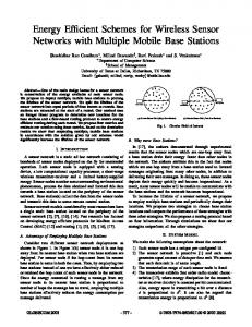
1) increase the default message size of TinyOS to accommodate the largest Nose message, or 2) fragment the large Nose messages at the source to fit the default TinyOS packets, and reassemble the fragments at the destination. Since TinyOS messages were the de facto mode of message exchange between the various layers in the TinyOS stack, increasing the default message size was not viable because it resulted in an overall RAM requirement that exceeded the available RAM capacity. Fragmentation/Reassembly (FR) was thus selected and implemented. A fragmentation layer was introduced between the application layer and routing layer of the source, and a reassembly layer was introduced between the application layer and routing layer of the destination. The FR module was been designed in a very modular fashion, so that any routing protocol can be “plugged” into the application. A simple stop-and-wait protocol with positive acknowledgement was introduced for error recovery, in the event that a fragment was lost in transit. If an ACK is not received at the source within a dynamically determined time frame, the fragment is assumed to be lost, and a retransmission procedure is initiated. The number of retransmissions is limited to a predetermined maximum to recover from a loss of route to the destination. Multi-hop communication in our application was made possible by using TinyAODV [24] as the routing protocol. TinyAODV is derived from the well-known Mobile Ad hoc NETworking (MANET) [25] routing protocol, the Ad hoc On-demand Distance Vector (AODV) [26] routing protocol. TinyAODV retains only a subset of AODV’s features so that it can fit within the memory constraints imposed by the motes (and thus tiny). Fig. 4 shows the multi-hop communication schematic between Nose Server and the Nose in the Nose Service application. With reference to our architecture, the Nose Service plays the role of the collector, while the motes network and the Nose sensor form part of the device layer. We only used the following three commands: LOAD PROFILE, START IDENTIFICATION, and FETCH RESULT. These commands were issued by the Nose service and were transmitted to the Nose via the multi-hop wireless motes network. Fig. 5 shows the sequence of message exchanges between the Nose Server and the Nose. The following section describes the use of a proof-ofconcept prototype, and the resulting lessons learned. E. Proof-of-Concept Implementation The objective of our prototype implementation was to demonstrate the interaction of various entities (owned by multiple vendors) in a secure, controlled-access environment. Fig. 6 shows the various components of the prototype unified mutli-owner sensor network architecture. Fig. 7 shows the schematic of the multiple-ownership architecture. Two clients, user A and user B are used here, and the clients were each assigned different permissions to access and control the Nose. The client programs of both users
Fig. 4. Nose Server - Nose Communication via Multi-hop Wireless motes Network
Fig. 6.
Fig. 5.
Various Components of Prototype Architecture
Sequence of Message Exchange between Nose Server and Nose
were run on the same machine. We had server-1 running the ACE Core Services: the ACE Service directory, ACE User database service, and the ACE Regional database service. To demonstrate that the various components of the architecture could function in a distributed manner, we ran the Nose (chemical sensor) service on server-2. The nose server, which was built to IEEE 1451 specifications, was connected to an electronic nose via a multi-hop MICA motes network. Here, we showed that the clients could successfully execute only the commands that they were permitted to execute on the Nose, and were not able to execute commands for which they did not have the necessary permissions. Fig. 8 shows the actual demonstration configuration. 1) Hardware Specifications: • Server 1- Pentium III 750 MHz processor, 256 MB RAM, 10 GB HDD, Red Hat Enterprise Linux WS release 4 • Server 2- Dell Latitude D820, Pentium Dual Core T2500 2.0 GHz, 1 GB RAM, 80GB HDD, Fedora Core 5 (2.6.16) • Client Host - Pentium III 933 MHz processor, 512 MB RAM, 80 GB HDD, Red Hat Enterprise Linux WS release 4 • motes - MICA2 motes, 915 MHz, programmed using nesC (TinyOS 1.1.7) on a mib510 board (serial port). The transmission power level of the motes was reduced by 20dB to reduce the range of the radios to ∼5 ft, to demonstrate multi-hop routing. • Electronic Nose - Cyranose 320, serial # B001203158, mounted on a chemistry lab stand 2) Software Specifications:
Fig. 7. Demonstration Architecture showing Secure Access and Control of Sensor Capabilities in a Multi-Ownership Scenario
•
Server Application - The server application or the Nose service could issue commands to, and receive responses from the Nose. It contained the Nose NCAP mentioned above, so that all communication between the client, server and sensor was IEEE 1451 compliant. We used the JDDAC library, which has been built around IEEE 1451 specifications, to build our Nose NCAP. It involved designing a new Function Block to process and issue Nose-specific commands and a Transducer Block to provide serial port IO capability. The ACE communication channels provided the communication fabric between the client and the server. The Nose server exposed standard ACE interfaces to the client, so that the Nose service could leverage the ACE security, authentication and authorization mechanisms that are critical to our architecture.
Fig. 9.
Fig. 8.
•
User A successfully fetches profile from the Smellprofile Database
Demonstration Set up showing the various hardware components
Client Application - The sole purpose of the Nose Client was to issue IEEE 1451-compliant commands to the server, based on the user input. The client application was a simple GUI which simply lists the commands that can be executed on the Nose. To ensure inter-operability with ACE, all client applications were written in Java and used Remote Method Invocation (RMI) [27] to communicate with the sensor services. With JAVA-RMI, the services present themselves as remote objects. The applications get handles to these remote objects and use them to talk to the services. As recommended in the JDDAC documentation [20], Eclipse IDE was used to build the Client and Server applications. The version of java that we used was JDK 1.5.0.8.
F. Demonstration Procedure As mentioned earlier, here we model each of components of the network (Nose, Smell profile Database, etc.) as belonging to a different organization, and the clients were not necessarily associated with any of these organizations. This lends itself to a truly multi-ownership scenario, where the clients require access to resources that span multiple administrative boundaries. The clients already possess the necessary authorization (credential files). We do not discuss how each client obtained the credential files from an appropriate CA - we simply assume that the authorization was obtained via some legitimate method. The following were the permissions assigned to each user: 1) User A: LOAD PROFILE, 2) User B START IDENTIFICATION, and FETCH RESULT In addition to these permissions, the credential file contains other relevant information such as the time frame within which the user is permitted to execute these commands, the room that contains the Nose (regional information), etc. To execute LOAD PROFILE, first a profile had to fetched from the smell profile database (repository layer), and then loaded into the Nose. Using the simple client GUI provided
Fig. 10. User A successfully executes LOAD PROFILE, but unsuccessful in executing START IDENTIFICATION
(client application), user A was able to successfully retrieve the file corresponding to “Isoproply Alcohol - Water” profile from the database of smell profiles. Fig. 9 shows the sequence of associated message exchanges that leads to fetching the smell profile. As a second step, user A could successfully load the smell profile into the Nose by executing the LOAD PROFILE command. User A then tried to execute START IDENTIFICATION command, but received an “Access Denied” error message due to lack of permissions. Fig. 10 shows the sequence of message exchanges that lead to successful execution of LOAD PROFILE, and an unsuccessful attempt in executing START IDENTIFICATION. Using the client application program, user B was able to execute the START IDENTFICATION command successfully. The smell print of “Isopropyl Alcohol - Water” had been preloaded into the Nose by user A. A vial containing isopropyl alcohol was located under the Nose, and the START IDENTIFICATION command was issued. Once identification was completed successfully, execution of the FETCH RESULT successfully fetched the result of the identification. User B was, however, unsuccessful when trying to load a new smell profile using the LOAD PROFILE command, due to lack of authorization to access the smell profile database, or to load a profile into the Nose. Fig. 11 shows the associated sequence of messages that led to successful execution of
•
•
Fig. 11. User B successful in executing START IDENTIFICATION, but unsuccessful in executing LOAD PROFILE
START IDENTIFICATION and unsuccessful attempt at executing LOAD PROFILE. G. Summary of Experiences The above-mentioned demonstration validates the design of the proposed architecture. Our experience with the prototype implementation provided a better understanding of some of the issues that we listed in Section II. Lessons learned include: • Scalability: The architecture does not require the control components to be co-located with one another or with the devices, and functions in a very distributed fashion. Thus, the architecture is scalable. However, we have not conducted any formal studies to assess the scalability of our architecture, and such evaluation is definitely an area of future work. • Security/Access/Control Policies for Multiple Organizations: The KeyNote trust management system turned out to be an excellent choice for formulating and enforcing security, control and access policies for components belonging to different organizations. However, the policy specification language lacked structure and proved to be cumbersome when specifying policies for a large number of heterogenous sensors, each with multiple functionalities. A new policy specification language, with a hierarchical structure is being considered to overcome this problem. • Software Support: The ACE architecture software is perhaps the most critical software component of the system. ACE provided authentication, authorization and secure communication services. The other major software component was the IEEE 1451 library. IEEE 1451 enabled future extensibility of supported sensors with minimum software developmental effort. However, integrating the IEEE 1451 library into the ACE architecture required significant effort. We expect that similar effort levels will be required if we wish to integrate other sensor interface standards into the system. A convenient improvement will be to enhance the system to support these standards as simple plug-in modules, so that deployment of this architecture is simplified and rapid.
•
Device Reconfiguration: The use of a standardized interface to communicate with the sensors greatly reduces the need for device as well as system reconfiguration. The IEEE 1451-compliant sensors are also called smart transducers - they have the ability for self-identification, and can be configured during service start-up. Sensors can be reconfigured, added or removed from the system with great ease. Device Naming/Addressing: The use of the regional database in the developed architecture ensures that the addresses or names assigned to the devices only have local significance. This greatly simplifies the addressing or naming of the devices. If the sensors are moved to a different location, then the corresponding entry in the regional database will be updated, and (possibly) the device will be assigned a new address. Hardware Support: For our implementation, we entirely used COTS wireless sensor components (motes), which are not only affordable, but also easy to deploy. The limiting factor of motes is that it requires programming using NesC in the TinyOS platform. A more attractive alternative could be to use SunSpots [28] or gumstix [29] that allow for programming in Java. We are currently exploring these technologies as possible wireless sensor network building components. VII. C ONCLUSIONS
In this paper, we described a sensor network architecture which integrates various component technologies into a unified framework that is rapidly deployable, scalable and owned by variety of organizations. We also created a proof-of-concept implementation, which is a IEEE 1451 - based multi-hop wireless sensor network application. In our framework, the control mechanisms provide for authentication of the client (by the device of the controlling application), authorization to access and control the device based on an established security policy, confidential transmission, and integrity checks. The data flow mechanism supports real time exchange of data between applications and devices that is private and checked for integrity. Security policies are specified and enforced via a KeyNote Trust Management System. This prototype demonstrated the salient features of our unified multi-ownership architecture, namely assured access and fine-grained control to the various components in the system across multiple administrative domains. In particular, we showed that the users could access and control resources (devices, functions of devices) belonging to multiple owners, provided they had the necessary authorization to do so. Unauthorized users were denied access to the resources. R EFERENCES [1] A. Hac. Wireless Sensor Network Designs. Wiley & Sons, West Sussex, England, 2003. [2] D. Estrin, D. Culler, K. Pister, and G. Sukhatme. “Connecting the Physical World with Pervasive Networks”. IEEE Pervasive Computing, pages 59–69, January-March 2002.
[3] I. F. Akyildiz, W. Su, Y. Sankarasubramaniam, and E. Cayirci. “Wireless Sensor Networks: A Survey”. Computer Networks, 38:393–422, September 2002. [4] Robert Szewczyk, Joseph Polastre, Alan Mainwaring, and David Culle. “Lessons from a Sensor Network Expedition”. In European Workshop on Wireless Sensor Networks (EWSN ’04), pages 66–80, Berlin, Germany, 2004. [5] Gary J. Minden, Joseph B. Evans, Arvin Agah, Jeremiah W. James, and Leon Searl. “Architecture and Prototype of an Ambient Computational Environment: Final Report”. Technical Report ITTC-FY2004-TR-23150-09, Univ. of Kansas, July 2003. http://www.ittc.ku.edu/publications/documents/ Minden2003_23150-09.pdf. [6] J.Mauro. “Security Model in the Ambient Computational Environment”. Master’s thesis, Dept. of EECS, The University of Kansas, USA, 2004. http://www.ittc.ku.edu/research/thesis/ documents/james_mauro_thesis.pdf. [7] M. Botts, G. Percival, C. Reed, and J. Davidson. “OGC Sensor Web Enablement: Overview and High Level Architecture, OGC 06-050r2”. http://www.opengeospatial.org/pt/06-046r2. [8] Bryan L. Gorman, Mallikarjun Shankar, and Cyrus M. Smith. “Advancing Sensor Web Interoperability”. Sensors, 22(4):14–18, April 2005. http://www.sensorsmag.com/sensors/Homeland+ Security/Advancing-Sensor-Web-Interoperability/ ArticleStandard/Article/detail/185897. [9] P. B. Gibbons, B. Karp, Y. Ke, S. Nath, and S. Seshan. “Irisnet: An Architecture for a Worldwide Sensor Web”. IEEE Pervasive Computing, pages 22–33, Oct-Dec 2003. [10] M.Botts. “Technical Specification for Sensor Model Language (SensorML) - Version 0.0, Open Geospatial Consortium, OGC 05-086r2”. http://portal.opengeospatial.org/files/ ?artifact_id=13879. [11] John Heidemann, Fabio Silva, Chalermek Intanagonwiwat, Ramesh Govindan, Deborah Estrin, and Deepak Ganesan. “Building Efficient Wireless Sensor Networks with Low-Level Naming”. In Symposium on Operating Systems Principles, pages 146–159, Chateau Lake Louise, Banff, Alberta, Canada, October 2001. ACM. [12] Yong Yao and Johannes Gehrke. “The Cougar Approach to In-Network Query Processing in Sensor Networks”. ACM SIGMOD Record, 31(3), September 2002. [13] M. Blaze, J. Feigenbaum, J. Ioannidis, and A. Keromytis. “The KeyNote Trust-Management System Version 2”. RFC 2704, September 1999. [14] SatyaSree Muralidharan, Victor Frost, and Gary J. Minden. “SensorNet Architecture with Multiple Owners”. Technical Report ITTC-FY2008TR-41420-02, University of Kansas, July 2007. [15] Cyranose 320 Handheld Electronic Nose. http://www. smithsdetection.com/eng/1383.php. [16] The IEEE 1451 Standard. http://ieee1451.nist.gov/. [17] Microsoft’s Universal Plug and Play (UPnP). http://technet. microsoft.com/en-us/library/bb457049.aspx. [18] Optical Sensor Interface Standard. http://www.ntb.ch/pub/ bscw.cgi/d18647/OSIS_WG2_Standard_Documentation. pdf. [19] The IEEE 1451.0 Standard: A Smart Transducer Interface for Sensors and Actuators - Common Functions, Communications Protocols and Transducer Electronic Data Sheets (TEDS) Formats. http:// grouper.ieee.org/groups/1451/0/. [20] Java Distributed Data Acquisition and Control (JDDAC). https:// jddac.dev.java.net/. [21] MICA MOTES from Crossbow Technologies. http://www.xbow. com/Products/productdetails.aspx?sid=164. [22] ZigBee Alliance. http://www.zigbee.org/en/index.asp. [23] TinyOS. http://www.tinyos.net/. [24] TinyAODV. http://tinyos.cvs.sourceforge.net/ tinyos/tinyos-1.x/contrib/hsn/. [25] Mobile Ad hoc Networking (MANET) Charter. http://www.ietf. org/html.charters/manet-charter.html. [26] Charles E. Perkins, Elizabeth M. Belding-Royer, and Samir Das. “Ad hoc On-demand Distance Vector (AODV) Routing”. IETF RFC 3561. [27] Sun Microsystems. “Java Remote Method Invocation (Java RMI)”. http://java.sun.com/products/jdk/rmi/. [28] Sun Small Programmable Object Technology (SunSpots). http:// www.sunspotworld.com/. [29] GumStix. http://gumstix.com/.