employ a combination of continuous and bang-bang control effectors. An example of this important class of system is the. X-29A aircraft fitted with Vortex Flow ...
WA7 - 9:35
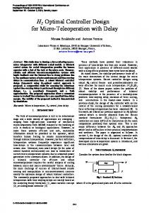
Pmwedlnps of the Amorlwn Conlml Confonnco SNIle. Washington Juna 1W
A UNIFIED CONTROLLER DESIGN METHODOLOGY FOR SYSTEMS WITH CONTINUOUS AND BANG-BANG CONTROL EFFECTORS John Valasek and David R. Downing Department of Aerospace Engineering, University of Kansas, Lawrence, Kansas 66045 every sample interval this variable structure controller uses either a) only the continuous effector and no bang-bang effector; orb) the continuous effector and the bang-bang effector in either the (+) or (-) state. Ideally, the controller should use the best features of each effector combination above in a particular situation to achieve a desired performance. This can be accomplished on-line by evaluating a designer specified cost function. Since the two types of control effector are not separated out as in previous methods, the controller for both parts of the complete system can now be designed in a unified fashion, i.e., in a single design phase where both controls are accounted for simultaneously. The SDR uses the following discrete cost function for a sampled continuous Linear Time Invariant (LTI) system as the number of samples N approaches infinity:
ABSTRACT A unified, systematic controller design procedure is introduced for the class of linear time invariant systems with use both continuous and bang-bang control effectors. The sampled-data regulator weighting matrices and cost function are extended to this class of system, and modulates the bangbang effector to achieve desired performance levels. Controller synthesis is illustrated for a generic second order plant with one continuous effector and one bang-bang effector. INTRODUCTION Real world control problems with challenging performance requirements can require dynamic systems to employ a combination of continuous and bang-bang control effectors. An example of this important class of system is the X-29A aircraft fitted with Vortex Flow Control (VFC) [l]. Figure 1 shows a block diagram for a generic control system of this type.
- N-l
J
=
1 ---(X:Q X, k=i
+
U,'R U,
+
2X,'MU,)
1
L
a
w"
where xk E , U, E ]wm , is positive definite, 0 and M are positive semi-definite. Minimizing (1) to get constant optimal gains, and closing the feedback loop with the standard SDR control law U,,= - K xk which accounts for only the continuous control effectors, the closed loop simulation equation for the sampled-data system becomes
CONTROLL.EII
Figure 1 Generic Control System with Continuous and Bang-Bang Control Effectors These systems have distinct continuous and piecewise constant elements and properties. Compared to the well established controller design methodologies for systems that use only continuous effectors [2] or only bang-bang effectors [3], existing synthesis techniques for the present class of system are designed by essentially trial and error and perhaps Monte-Carlo methods. A typical approach to controller design for this class of systems is to separate the piecewise constant part from the continuous part and conduct separate design phases [4]. In this paper, a unified systematic design methodology based upon the Sampled-Data Regulator (SDR) of [5] is developed for directly designing feedback control laws where both types of effectors are accounted for simultaneously. The important feature of this methodology is that the designer has direct control of the change from one candidate controller design to another. This makes it possible to tradeoff response performance against control activity, and tradeoff the use of the continuous against the bang-bang effectors.
where h is the integration stepsize and U,, contains only bangbang effectors. SUB-INTERVAL TRAJECTORY EVALUATION At the beginning of each sample interval, the system is simulated on-line forward in time, over a sub-interval of time equal to the sample interval, using each of the three candidate controller structures (Figure 2).
9-4 1 1 runcuun
LII~IIPUWS pius
U II (.)
A ' l l
Figure 2 Flowchart of Controller Evaluation and Selection
UNIFIED CONTROLLER DESIGN CONCEPT The present method considers the complete system to be controlled by two distinct, independent control systems. At
The candidate structure which generates the lowest cost in terms of state deviation and control activity, using (I), is selected and used during the upcoming sample interval. The operation of the
175
[4] Nammov, Boris Nikolaevich, Philosophy Of Nonlinear Control Systems, Mir Publishers, Moscow, 1990, p. 91.
continuous effector is unaffected. The on-line simulation can use either a full set of nonlinear dynamic equations or a reduced-order linear approximation. Using SDR gains the closed-loop system is stable for a range of initial conditions provided stabilizing gains are used, and the adaptive nature of the controller provides a certain degree of stability robustness with respect to real parameter variations.
[5] Dorato, Peter, et al, "Optimal Linear Regulators: The Discrete-Time Case," IEEE Transactions on Automatic Control, Volume AC-16, Number 6, Dec 1971, pp. 613-620.
CONTROLLER DESIGN ILLUSTRATION The example is the classic regulator problem. For consistency the same SDR weighting matrices and cost function are used to both design gains and evaluate trajectories. The generic LTI second order system is:
I
with continuous effector U, and bang-bang effector of ten times effectiveness U, . The open-loop system has A,,z = -.12 & 2.28j , on= 2.28 radlsec, and 4 = 0.054. The elements of the weighting matrices are held fixed at Q I I =0.91; Qz2=0.33; R,= 3.7. The only parameter which is varied to design the controllers is the weight on the bang-bang effector R, . To compare successive designs a weight of R, = 0.5 on the bangbang effector generates Design 1, a nominal system performance with only the continuous effector operating (Figure 3). The total discrete cost over the 30 second run is 5.91. Successively reducing the value of R, generates designs which use progressively more of the bang-bang effector. An R, value of 0.02 generates Design 2, which Figure 4 shows activates the bang-bang effector first in the positive state for a single pulse, and then in the negative state for two pulses. Design 2 has a discrete cost of 1.98, a reduction of 67%.
I
I
SUMMARY AND CONCLUSIONS A unified systematic design procedure, based upon the SDR and incorporating on-line future projection and evaluation of states, was developed for controller synthesis of LTI plants which are controlled by a combination of continuous and bang-bang control effectors. The systematic design procedure was applied to a generic second order LTI plant. Based upon the results of this work it is concluded that: 1) the present method provides a unified systematic controller design methodology for systems with both continuous and bang-bang control effectors; 2) the designer is provided with insight and the capability to directly tune the character of the closed-loop system response.
-
I
I
1
I
I
I
I
I
I
I
I
I
I
I
I
0
5
10
25
30
REFERENCES [l] Walchli, Lawrence A., et al, "High Angle-Of-Attack Control Enhancement On A Forward Swept Wing Aircraq" AIAA-92-4427-CP. [2] Ogata, Katsuhiko, Modern Control Engineering, PrenticeHall, Inc, Englewood Cliffs, NJ, 1970.
[3] Tsypkin, Ya. Z., Relay Control Systems, Cambridge University Press, Cambridge, England, 1984.
15 20 time (sec)
Figure 4 Design 2 Performance, Cost = 1.98
176