A Unified Design Framework for Mobile Robot Systems James Goodwin and Alan Winfield Bristol Robotics Laboratory (BRL), UK
[email protected];
[email protected]
Abstract. This paper describes a unified design framework for mobile robot systems. This design framework is concerned with the totality of the robot system, and is not constrained to components, architectures, middleware, hardware or software. It can be used to drive requirements analysis, design and implementation of new robot systems, or the classification of existing robot systems. Furthermore, it does not impose hardware, software or communication interfaces, therefore allowing flexible integration of new and legacy robot components. The framework is expressed in the Unified Modelling Language (UML), primarily using class diagrams. The creation of the framework using UML terminology has allowed us to clearly define the functionality of many common robot system components. It has also allowed us to define the exact meaning of the term ‘robot’.
1 Introduction Mobile robot engineering encompasses techniques from a wide variety of scientific and engineering domains. Electronics, mechanics, computer science, biology, chemistry, physics and psychology have all played a significant role in what is now referred to as robotics. With such a diverse background it is difficult to define the term ‘robot’. The problem is confounded by ambiguous descriptions and the overlapping of ‘Robotics’ with similarly unbounded scientific domains, such as ‘Cybernetics’ and ‘Artificial Intelligence’[5][6]. Intelligent, Autonomous and Unmanned are descriptions that immediately confuse not only the engineers of robot systems, but also the wider public. Mobile robots, such as wheeled robots and unmanned underwater vehicles, use a form of robot architecture. The term ‘robot architecture’ is commonly used to describe the software structure and its action selection methods [5]. The robot architecture provides the robot command structure and has a wide-ranging effect on the robots ability to perform its desired tasks. Further to traditional control systems, a robot’s architecture may be capable of performing deliberative actions. Traditionally, robot architectures are constrained to cognition and interaction with the vehicle. However, this paper will use a unified design framework to describe the overall operation and structure of the robot system, which may include other robots, users and environments and various action selection techniques. Whereas traditionally, robot architectures have focused on abstraction of hardware and software elements, the proposed unified approach does not attempt to impose such boundaries.
Workshop Proceedings of SIMPAR 2008 Intl. Conf. on SIMULATION, MODELING and PROGRAMMING for AUTONOMOUS ROBOTS Venice(Italy) 2008 November,3-4 ISBN 978-88-95872-01-8 pp. 513-524
2
James Goodwin and Alan Winfield
Since the 1950s, three major paradigms for Robot Architectures have been proposed; these are commonly referred to as Deliberative, Reactive and Hybrid [1]. Although these state-of–the-art techniques may meet the requirements imposed upon a robot, it is difficult for an engineer to identify the most appropriate techniques and design a robot system as a whole. This work is driven by three factors. Firstly, the robotics domain is flooded with robot architectures; it is desirable to focus the robotics community by identifying a framework, which accommodates these existing architectures. Secondly, providing a standard framework used in a variety of domains increases understanding, confidence and component re-use. This greater confidence can be transferred to systems which are otherwise difficult to test, such as spacecraft. Thirdly, designing robot systems is not an easy task. This paper provides engineering processes for requirements analysis, design, implementation and classification or robot systems. The design framework is expressed using the UML [2]. This allows the robot system to be rigorously described in a visual form.
2 Approach A comprehensive literature study has been undertaken into the major components of a robot architecture, their structure and the frameworks in which they exist [5]. The findings of the literature study are summarised here in two sections: section 3 documents Robot Systems Engineering, including common robot and software architectures, and section 4 analyses the common Robot Components, such as sensors, actuators and path planning algorithms. The work has been approached using a waterfall systems engineering approach, where a set of requirements are devised that drive design and subsequent testing. The requirements focus on five main users: 1. The Customer who requires the robot to perform a task or obtain information. 2. The Operator who will interact with the robot. 3. The Developer who will use tools and techniques to develop hardware and software components in the context of the unified framework. 4. The Researcher who will use and expand the unified framework with new techniques. 5. The Financier who will provide the resources necessary to undertake research and development. A unified framework should encompass state-of-the-art techniques already available within the robotics community. It should therefore accommodate all of the components described in Section 4. Two approaches to the design have been attempted. Initially, functional decomposition techniques were used in an attempt to identify a generic architecture containing generic components and interfaces [4]. Generic interfaces imply a defined level of interaction with the vehicle, using interaction software such as device drivers. This approach is limiting, as it requires the same interface layer for a number of vehicles. An efficient interface could not be identified and the approach was ultimately abandoned.
Workshop Proceedings of SIMPAR 2008 Intl. Conf. on SIMULATION, MODELING and PROGRAMMING for AUTONOMOUS ROBOTS Venice(Italy) 2008 November,3-4 ISBN 978-88-95872-01-8 pp. 513-524
A Unified Design Framework for Mobile Robot Systems
3
A second, successful, attempt has been made using object-oriented design. Object orientation introduces concepts, such as polymorphism and inheritance, which enable robust and flexible interface layers to be introduced. Using object-orientation and the UML led away from the idea of creating a generic architecture, primarily for software, towards a unified robot system design framework, encompassing multiple robots, users, interaction devices and environments. These object orientation concepts also allowed the design to provide a library of methods, some or all of which may be implemented in a solution. For clarification, the following terms are used: 1. Library: A set of generic and specialised components within the framework. 2. Solution: The selection of components and interactions used to solve a specific problem. 3. Architecture: In robotics, architecture is commonly used to describe the robot software structure and/or its action selection methods. More generally, architecture may be referred to as “The structure of components and their interrelationships” [3]). Architecture may relate to logical or physical components. 4. Framework: A structure in which components exist. “A framework can be used for developing a broad range of architectures and provide a basis for comparing and analysing architectures” [3]. It is envisaged that this approach will lead to greater acceptance within the robot community. Previously, the majority of work has focused on providing robot libraries (with little or no consideration for a unified framework) or architectural solutions (which tie the developer to specific components) [5]. Our approach provides the developer with a useful framework for visualisation and design, without imposing hardware and software interfaces. It also provides Customers, Operators, Developers, Researchers and Financiers with a visual representation of the robot system, therefore providing a standardized method of communicating requirements, designs and implementations.
3 Robot Systems Engineering When designing a robot, the whole system should be considered. This allows the developer to take into account all the factors that influence the robot itself. The developer should be concerned with the functionality that the system should exhibit, not necessarily if it is located in hardware or software. A robot design framework should therefore encompass a meta-model for the entire system, rather than simply encompassing the software aspects within the robot. When designing a robot system, the designer should consider many other aspects, including Robot Architecture, Control Systems, Self Invariance, Learning, Centralised and Distributed Processing, Multi-threading, Shared Resources, Robustness, Reliability, System Decomposition, Top-Down and Bottom-up design, Component re-use, Open and Closed Systems and Robot Software Development Tools [5].
Workshop Proceedings of SIMPAR 2008 Intl. Conf. on SIMULATION, MODELING and PROGRAMMING for AUTONOMOUS ROBOTS Venice(Italy) 2008 November,3-4 ISBN 978-88-95872-01-8 pp. 513-524
4
James Goodwin and Alan Winfield
4 Robot System Components A number of common components exist within a robot system. The generic component categories in Table 1 have been identified by examining a large number of robot architectures (26 in total) and their functionality [5]. Table 1. Generic robot system components. A detailed analysis of each component can be found in [5]. Component
Description
Perception
Perception of the environment provided by sensors and other robots. Perception includes map building, selfperception, internal system monitoring, fault detection and health monitoring. Planning to optimise the selection of, and route between goals. Guidance to determine the current location on a plan and provide the next action. Management to manage the activation and de-activation of behaviours and components. Action Selection providing decision making about the most appropriate action. Human Robot Interaction (HRI) providing motivation to the robot and feedback to the robot operators. Motivation allowing a robot operator to provide the robot with a set of objectives. The robot may choose, depending upon its own motivations (such as vehicle safety) to undertake some or all of these objectives. Behaviour providing one or more actions when provided with stimulus from vehicle sensors or perception. Actuators creating vehicle or manipulator motion when provided with an action. An action may be an element within a plan, or a single user instruction. Communications to communicate between distributed components, robots and HRI devices. Chassis providing the hardware framework of the robot. Processor to perform processing activities. Power to provide power to the robot components. This can include harvesting, transfer or storage systems. Payload to allow the robot to transport objects or tools, such as other robots or remotely deployed sensors.
Planning Guidance Management Action Selection Human Robot Interaction (HRI) Motivation
Behaviour Actuator
Communication Chassis Processor Power Payload
Workshop Proceedings of SIMPAR 2008 Intl. Conf. on SIMULATION, MODELING and PROGRAMMING for AUTONOMOUS ROBOTS Venice(Italy) 2008 November,3-4 ISBN 978-88-95872-01-8 pp. 513-524
A Unified Design Framework for Mobile Robot Systems
5
5 Design The unified design framework is split into dynamic and static models. Dynamic models express the flow of control and data between common activities. Static model class diagrams are used to describe the overall framework and structure in which components reside. Furthermore, new techniques can be added to the class structure as and when they become available. 5.1 Dynamic Modelling Section 1 has identified three architecture paradigms; namely deliberative, reactive and hybrid. This work has used the UML activity diagrams to illustrate flow of data and control amongst the main components of these three paradigms using common components, such as sense, plan and act. Table 2 describes the design patterns commonly found within robot systems. These design patterns can be used to build the 26 architectures analysed in [5]. These design patterns may then be used to develop new architectures using the unified framework classes of the static model. It is our intention to expand upon these existing design patterns to include other generic robot system processes, such as SLAM and hierarchical planning [5]. Table 2. Robot Architecture Design Patterns. Detailed design patterns are provided within [5]. Design Pattern
Description
Sense-Act (SA) Sense-Decide-Act (SDA) Sense-Plan-Act (SPA)/ Sense-Model-Plan-Act (SMPA) Parallel Sense-Plan-Act (SPA) Action Selection (Trigger based) Action Selection (Action based) Repair-based planning
Used to directly link sensor data to actuators. Used to determine an appropriate action, based upon a sensor value. Used to describe the process of creating and executing a new plan based upon sensor information.
Allowing Sense, Plan and Act components to act in parallel, at potentially differing frequencies. Selecting an appropriate action from a set of pre-defined actions. Selecting an appropriate action from a set of newly created actions. Repairing an existing plan to accommodate a change in the robot or environment. Determining the position and current action within a Guidance plan. Three-level architecture Creating and following an appropriate trajectory based upon sensor inputs. (Trajectory style) Three-level architecture Creating and following a sequence of controller activations based upon sensor inputs. (Management style) The combination of a Three-Level architecture with Hybrid Three-level action selection and behaviours to form a reactive and architecture deliberative system.
Workshop Proceedings of SIMPAR 2008 Intl. Conf. on SIMULATION, MODELING and PROGRAMMING for AUTONOMOUS ROBOTS Venice(Italy) 2008 November,3-4 ISBN 978-88-95872-01-8 pp. 513-524
6
James Goodwin and Alan Winfield
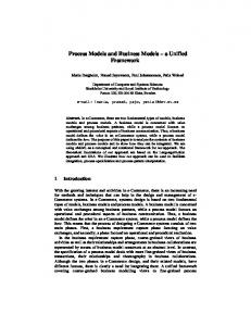
5.2 Static Modelling Static Modelling is used to define the structure of the robot system. This structure forms the backbone of the unified framework. The static models use UML classes to represent each component of the system. Each component may be subdivided into further components or types. The following sections describe the base classes of the framework. It is intended that any modifications or additions to the methods or parameters of the base classes will result in a derived class. This Open-Close Principle (OCP) approach enables the framework to be expanded whilst still allowing for backwards compatibility [7]. 5.3 Robot System A robot system can, depending upon the designer’s point of view, be described as: 1. The systems and components contained within a robot, or 2. The system in which the robot exists. This unified approach will accommodate both descriptions. A robot system can therefore consist of environments, robots, users and interaction tools. Users may interact with robots and environments using interaction tools. Examining the entire system enables the developer to treat the robot as a team member, rather than a subservient agent. Furthermore, examining the system in which the robot exists allows collective, multiple or social robot development to be integrated within the same framework. class Robot System
Robot System
informs instructs 0..* 1..* Env ironment
senses 1 operates within
1
1
1
manipulates 1 and moves within 0..*
0..*
0..*
0..*
1..*
0..*
0..*
Robot
informs
0..*
User 0..*
informs
0..* 0..*
0..* 0..*
0..*
instructs 0..*
1
0..* operates
Interaction
0..*
0..*
0..*
0..*
0..*
0..*
0..*
senses
senses
manipulates
manipulates
manipulates senses
Fig. 1. Robot System. Describes of high level robot system, not the robot’s components
The robot system is described in Fig. 1. The entire robot system may be real or virtual, or comprise both real and virtual components.
Workshop Proceedings of SIMPAR 2008 Intl. Conf. on SIMULATION, MODELING and PROGRAMMING for AUTONOMOUS ROBOTS Venice(Italy) 2008 November,3-4 ISBN 978-88-95872-01-8 pp. 513-524
A Unified Design Framework for Mobile Robot Systems
7
The following sections describe the Environment, User, Interaction and Robot classes. These classes are described in more detail within [5]. 5.4 Environment The Environment class exists within the robot system (i.e. the real world) and the robot’s perception (i.e. the robot’s world map). The environment may be real or virtual (i.e. may exist within software). In the virtual environment, or robot perception, it is necessary to use a representation. This representation is a replica of the real environment and is used for simulation and/or planning. Common representation types include grids, graphs, surfaces, databases and semantic maps [5]. Some or all of these representations may be used to describe the environment. 5.4 User The User may interact directly with a Robot by sensing its position or manipulating its configuration. The User may also, more commonly, interact with the Robot using an Interaction device. The User will provide, or be provided with the mission requirements; it is then their responsibility to convert the mission requirements into an appropriate form using an appropriate Interaction device. 5.5 Interaction The user may instruct the robot using touch, speech, facial expressions or movements using a Human Robot Interaction (HRI) device. The robot may respond through movement or though an HRI device, such as a graphical display. The HRI device is used to define the robot’s motivation or control its actuators. Motivation consists of a plan. Once a plan has been created it may be communicated to the robot using a form of communication contained within the Communication class. The plan may comprise high-level goals, which the robot may process in order to form a planned path. 5.6 Robot The robot class is described in Fig. 2. A robot consists of zero or one vehicles, associated with zero or more cognitive components. Common robot variants include: 1. A single vehicle without cognition. For example, a remote control car provides methods to communicate with and control the vehicles actuators. The cognition is embedded within the user. 2. A single vehicle with cognition (embodied intelligence). For example, a robot with a level of on-board autonomy. This on-board autonomy may relate to the ability to plan a route.
Workshop Proceedings of SIMPAR 2008 Intl. Conf. on SIMULATION, MODELING and PROGRAMMING for AUTONOMOUS ROBOTS Venice(Italy) 2008 November,3-4 ISBN 978-88-95872-01-8 pp. 513-524
8
James Goodwin and Alan Winfield
In some cases, multiple robot vehicles will be controlled by a single cognitive component. In which case, the developer should create multiple robot instances, most of which contain only vehicles and one of which also contains a cognitive component. class Robot
Robot
0..1
0..*
Vehicle
Cognition operates 0..1
0..1
Fig. 2. Robot. The vehicle and cognitions classes are illustrated in Fig. 3 and Fig. 4.
The developer is limited to only 1 vehicle per robot. As with all other components within the framework, there is no assumption about the location of cognition. The cognition of a robot, may therefore physically reside within the hardware of another robot. The vehicle class is shown in Fig. 3 and described in Table 3. class Vehicle
Vehicle
*
0..* Plan Element
0..* Sensor
0..* Beacon
0..* Chassis
0..* Communication
0..* State
0..* Processing
0..* Dynamic Model
0..* Payload
0..* Pow er
Actuator
Fig. 3. Vehicle. A vehicle has the ability to sense, communicate or interact with its environment, users, or other vehicles. A vehicle may be real or simulated. The vehicle class describes the vehicle chassis including its geometry and features.
As the vehicle may exist as hardware or software, the cognitive part of the robot may not necessarily be able to access information stored within the vehicle class. Due to this, the robot may build a self-perception, which it may use for planning purposes. For example, a real vehicle will have a shape and this shape may be required for path planning. However, the robot may not be able to simply request the vehicle’s shape information and will therefore require a self-perception of shape.
Workshop Proceedings of SIMPAR 2008 Intl. Conf. on SIMULATION, MODELING and PROGRAMMING for AUTONOMOUS ROBOTS Venice(Italy) 2008 November,3-4 ISBN 978-88-95872-01-8 pp. 513-524
A Unified Design Framework for Mobile Robot Systems
9
Table 3. Vehicle classes. Class
Description
Actuator
Provides functionality to move the robot within or interact with the robot’s environment. Internal to the robot, the actuator may access sensor information for low-level feedback. Provides functionality to access sensor information. This sensor information may be provided on a continuous stream or polled. As with the Actuator class, a number of toolboxes exist, which may be used within the framework. Provides a signal to other robots, or may be used by active sensors, such as sonar. Describes the behaviour of the robot when provided with actuator demands. This dynamics/kinematics model can be used for path planning, simulation or fault detection. Allows the robot to send and receive plans or perceptions. The communications class can also include higher-level middleware. Describes the robot’s position and orientation within its environment. Provides the processing and memory components available on the robot. Provides the robot the capacity to transport other robots (including remote sensors) and users. Provides energy sources and storage to run the vehicle components.
Sensor
Beacon Dynamics /Kinematics Model Communication State Processor Payload Power
class Cognition
Cognition
Motiv ation
Perception
Behav iour
Planner
Action Selection
Guidance
Management
Fig. 4. Cognition. The cognition class is used to reason about and determine an appropriate interaction with the robot’s environment, other robots and users. The cognition class performs this operation through the Motivation, Perception, Planner, Behaviour, Guidance, Action Selection and Management classes.
The Cognitive class is illustrated in Fig. 4. The cognition class is used to reason about and determine an appropriate interaction with the robot’s environment, other robots and users. The cognition class performs this operation through the Motivation, Perception, Planner, Behaviour, Guidance, Action Selection and Management classes.
Workshop Proceedings of SIMPAR 2008 Intl. Conf. on SIMULATION, MODELING and PROGRAMMING for AUTONOMOUS ROBOTS Venice(Italy) 2008 November,3-4 ISBN 978-88-95872-01-8 pp. 513-524
10
James Goodwin and Alan Winfield
6 Engineering Process The following engineering processes describe the use of the unified framework within an engineering project following a waterfall or V-model. Figure 5 illustrates the role of the unified design framework within academia and industry. The unified framework plays a core role in the definition of requirements, the identification of techniques/tools and components, the identification of technology gaps within the robot systems industry and the provision of new techniques.
User Requirement
Managed expectation
Requirements Engineer
Requirements specification
Systems Engineer/ Architect Initial expectation
Requirements structure
Identification of techniques
Fund work to provide new components
Identify holes in framework Unified framework Provide new solutions
Researcher
Development Engineer
Enhance and implement solutions
Fig. 5. Engineering stakeholders. The diagram illustrates the role of the unified design framework within academia and industry. 6.1 Requirements Capture Scope and Requirements capture within an engineering project may take on various forms. It may include interviews with customers, operators, financial backers and developers. User requirements should not be based upon the robot’s internal operation, but on how it interacts with its operators and environment. Requirements analysis may be made more effective if the requirements are categorised. It is therefore appropriate to lead the requirements analysis using the Robot System described in Section VI. Basic requirements capture should ask the following questions:
Workshop Proceedings of SIMPAR 2008 Intl. Conf. on SIMULATION, MODELING and PROGRAMMING for AUTONOMOUS ROBOTS Venice(Italy) 2008 November,3-4 ISBN 978-88-95872-01-8 pp. 513-524
A Unified Design Framework for Mobile Robot Systems
11
1. In what environments must the robots operate? 2. Is the environment deterministic? 3. Is the environment static? 4. Are there any non-deterministic dangers, which the robot must react to? 5. What interaction is required with the environment? 6. Is it does the user require sensory feedback from the environment? 7. Is it necessary to manipulate the environment? 8. What interaction is required between the user and robot? 9. What is the workload of the user? 10.What training is available? 11.What are the mission requirements? 12.How accurate must it perform its operations? 13.What functions must the robot perform? 14.Are their any optimisation criteria, for example, time or energy? 15.What is the desired failure rate, therefore does the system warrant critical design methods, redundancy or fault detection? The answers to these questions will drive the design process, and requirements should aim to constrain the possible solutions. The operational environment will eliminate various types of robot, sensors, communications and actuators. An underwater environment, for example, will immediately limit the methods available for communication and navigation. The user interaction required will result in an appropriate HRI device and thus a selected level of autonomy. A military user, for example, may be required to perform tasks whilst operating the HRI and is likely therefore to require a robot with high levels of autonomy. An academic researcher, for example, may wish to drive a robot exploration task and will therefore require low-level interaction and thus lower levels of autonomy. 6.2 Design Design can be considered as a method of navigating or searching a solution space. As with path planning, navigation of a design solution space can be approached using search techniques, such as graph searches, dynamic programming or evolutionary algorithms. In both path planning and design the developer wishes to find the best solution, in terms of cost and performance, with the least possible effort. Design using the unified framework can be approached by for searching and eliminating components, based upon requirements. 6.3 Implementation The design stage will have produced a list and description of components, including hardware, software, simulated and real. Some components may already exist, others may require further development, and some may simply be concepts. Implementation fulfils two objectives: 1. To meet specific requirements of an existing project
Workshop Proceedings of SIMPAR 2008 Intl. Conf. on SIMULATION, MODELING and PROGRAMMING for AUTONOMOUS ROBOTS Venice(Italy) 2008 November,3-4 ISBN 978-88-95872-01-8 pp. 513-524
12
James Goodwin and Alan Winfield
2. To advance technology readiness, therefore providing components ready for use in future projects. When attempting to meet the requirements of an existing project, it is recommended to rely upon existing components [5].
7 Conclusion The unified design framework fundamentally allows the users, requirements engineers, project managers, consortium members, design engineers, component providers and academic researchers to categories existing techniques using the same framework. This enables the responsibilities of each stakeholder to be more clearly defined and provides a structure for the development of new robot systems. Furthermore, the framework provides design patterns, which allow these stakeholders to combine common components in order to produce robot architectures. It is a difficult task for an engineer to design and develop a robot system, as they are presented with an enormous number of sensors, actuators, vehicle types, software techniques and decomposition methods. The unified design framework simplifies this task and bridges the gap between techniques available within academia and those at the disposal of engineers. Ground robot, autonomous underwater vehicle and asteroid landing robot case studies are provided in [5]. It is ultimately envisaged the a tool will be developed to enable each stakeholder within the field of robot systems engineering to communicate requirements, ideas, tools and techniques using the unified design framework.
References 1. 2. 3. 4.
5.
6. 7.
Gat, E. (1997) On three-layer architectures. Artificial Intelligence and Mobile Robots. MIT/AAAI Press. Holt, J. (2001) UML for systems engineering. ISBN 0 85296 105 7, IEE 2001. Biggs, B. (2005) Ministry of Defence Architectural Framework (MODAF) [online]. Available from: www.modaf.com/files/050203%20MODAF%20IEE%20v1a.ppt Goodwin, J., Winfield, A., Zhu, Q. (2003) Towards a Generic Architecture for Autonomous Landing Systems. Proc. Towards Intelligent Mobile Robots (TIMR, 03), Bristol, August 2003. Goodwin, J. (2008) A Unified Design Framework for Mobile Robot Systems. PhD Thesis. Bristol Institute of Technology, University of the West of England, October 2008. Available from http://www.AutonomousSolutions.co.uk Murphy, R. (2000) Introduction to AI Robotics. MIT Press. Meyer, B. (1988) Object-Oriented Software Construction. Prentice Hall. ISBN 0136290493.
Workshop Proceedings of SIMPAR 2008 Intl. Conf. on SIMULATION, MODELING and PROGRAMMING for AUTONOMOUS ROBOTS Venice(Italy) 2008 November,3-4 ISBN 978-88-95872-01-8 pp. 513-524