Email: {ss07r,sqc,lh}@ecs.soton.ac.uk, http://www-mobile.ecs.soton.ac.uk. AbstractâIn this ... Bell Lab's Layered Space-Time (BLAST) scheme [2] was designed.
1
A Unified MIMO Architecture Subsuming Space Shift Keying, OSTBC, BLAST and LDC Shinya Sugiura, Sheng Chen and Lajos Hanzo School of ECS, University of Southampton, SO17 1BJ, UK, Tel: +44-23-8059-3125, Fax: +44-23-8059-4508 Email: {ss07r,sqc,lh}@ecs.soton.ac.uk, http://www-mobile.ecs.soton.ac.uk
Abstract—In this paper, motivated by the recent concept of Spatial Modulation (SM), we propose a novel Generalized Space-Time Shift Keying (G-STSK) architecture, which acts as a unified Multiple-Input Multiple-Output (MIMO) framework. More specifically, our G-STSK scheme is based on the rationale that P out of Q dispersion matrices are selected and linearly combined in conjunction with the classic PSK/QAM modulation, where activating P out of Q dispersion matrices provides an implicit means of conveying information bits in addition to the classic modem. Due to its substantial flexibility, our G-STSK framework includes diverse MIMO arrangements, such as SM, Space-Shift Keying (SSK), Linear Dispersion Codes (LDCs), Space-Time Block Codes (STBCs) and Bell Lab’s Layered Space-Time (BLAST) scheme. Hence it has the potential of subsuming all of them, when flexibly adapting a set of system parameters. Moreover, we also derive the Discrete-input Continueousoutput Memoryless Channel (DCMC) capacity for our G-STSK scheme, which serves as the unified capacity limit, hence quantifying the capacity of diverse MIMO arrangements. Furthermore, EXtrinsic Information Transfer (EXIT) chart analysis is used for designing our G-STSK scheme and for characterizing its iterative decoding convergence.
I. I NTRODUCTION Over the last two decades diverse Multiple-Input Multiple-Output (MIMO) arrangements have been developed for achieving diversity, multiplexing and/or beamforming gains [1]. For example, while Bell Lab’s Layered Space-Time (BLAST) scheme [2] was designed for high-rate transmission, the class of Space-Time Block Codes (STBCs) [3] was developed for achieving a beneficial diversity gain. Furthermore, in [4] Hassibi and Hochwald proposed the unified space-time concept of Linear Dispersion Codes (LDCs), which strikes a flexible tradeoff between the attainable diversity and multiplexing gains. Recently, Melash et al. proposed the sophisticated concept of Spatial Modulation (SM) [5], which employs a novel MIMO encoding principle, where the transmitter activates one out of M transmit Antenna Elements (AEs), whose antenna-activation process acts as an additional means of conveying information bits, and then only the activated antenna transmits a signal modulated with the aid of the classic L-point constellation, such as Phase-Shift Keying (PSK) and Quadrature Amplitude Modulation (QAM). Unlike BLAST, the SM does not transmit simultaneously via M AEs, hence single-antennabased low-complexity ML detection can be employed at the receiver, while dispensing with symbol-level Inter-Antenna Synchronization (IAS) at the transmitter. The special case of SM is constituted by the scenario, where we deactivate the classic PSK/QAM signalling and simply use the presence or absence of energy assigned to a specific antenna, which is also referred to as Space Shift Keying (SSK) [6]. The SSK was investigated both for uncoded and for turbocoded scenarios, while the optimal ML detector designed for the uncoded SM/SSK scheme was presented in [7]. Although SM/SSK has the potential of outperforming other MIMO arrangements [5]– [7], SM/SSK was not designed for achieving any transmit diversity The financial support of the EU under the auspices of the Optimix project and of the EPSRC UK is gratefully acknowledged. The work of S. Sugiura was sponsored in part by the Toyota Central Research & Development Laboratories, Inc., Japan.
gain and hence has to rely on the provision of receive diversity in order to combat the effects of fading channels. Against this background, the main contribution of this paper is that we propose a Generalized Space-Time Shift Keying (G-STSK) scheme, where the SM/SSK concept is extended to include two dimensions, namely space as well as time, and hence it becomes capable of striking a flexible tradeoff between the attainable diversity and multiplexing gains. More specifically, in G-STSK P out of Q dispersion matrices are activated during each transmission interval. Owing to its high flexibility, the G-STSK framework subsumes most of the above-mentioned MIMO arrangements, such as SM/SSK, LDC, STBC as well as BLAST, and therefore has the potential of flexibly mimicking all of them. Additionally, we conceive the optimal ML detector designed for uncoded G-STSK systems and the softdemodulator conceived for the coded G-STSK systems. Moreover, we also derive the Discrete-input Continueous-output Memoryless Channel (DCMC) capacity [8] of our G-STSK scheme, which serves as the unified capacity, hence characterizing diverse MIMO arrangements. EXtrinsic Information Transfer (EXIT) chart analysis [9] is invoked for designing our G-STSK scheme and for characterizing its iterative detection process. The remainder of this paper is organized as follows. Section II introduces the system model of our G-STSK scheme, and then both the corresponding hard- and soft-decision detectors are presented in Section III. In Section IV we derive the DCMC capacity of our GSTSK scheme, while Section V provides our performance results. Finally, the paper is concluded in Section VI. II. S YSTEM M ODEL In this section we introduce our G-STSK scheme and then demonstrate that it subsumes many MIMO schemes as its special cases. Let us first consider the general block-based space-time system model of [1] Y (i) = H (i)S(i) + V (i),
(1)
where Y (i) ∈ C N ×T are the signals received at the receiver equipped with N AEs, while S(i) ∈ C M ×T represents the space-time codewords transmitted over T symbol durations from the transmitter having M AEs. Furthermore, transmission i represents the block index. It is also assumed that each component of the channel matrix H (i) ∈ C N ×M and the noise matrix V (i) ∈ C N ×T obeys the complex-valued Gaussian distribution of CN (0, 1) and CN (0, N0 ), respectively, where N0 represents the noise variance. A. G-STSK Modulation Fig. 1 shows the schematic of our G-STSK’s transmitter. In the GSTSK bit-to-symbol mapping scheme, B = log2 f (Q, P )+P log2 L bits per block are mapped to a space-time codeword S(i), where f (Q, P ) is calculated from Q and P as f (Q, P ) = 2ι , while the
2
TABLE I E XAMPLE OF GSTSK(2, 2, 2, 4, 2) MODULATION SCHEME OF F IG . 1, MAPPING B = 4 BITS PER SPACE - TIME BLOCK , WITH THE AID OF BPSK
G-STSK block B1
Source B
dispersionmatrix activation
S/P
Fig. 1.
Space-time mapper M
PSK/QAM PSK/QAM
B2
Transmitter structure of our G-STSK scheme.
integer ι satisfies the following inequality1
�
ι
2 ≤
Q P
�
< 2ι+1 .
(2)
Firstly, B = log2 f (Q, P ) + P log2 L input bits are S/P converted to B1 = log2 f (Q, P ) bits and B2 = P log2 L bits. Then, at the dispersion-matrix activation block of Fig. 1, P out of Q preassigned dispersion matrices Aq� ∈ C M ×T (q � = 1, · · · , Q) are activated according to B1 = log2 f (Q, P ) input bits, in order to have A(p) (i) (p = 1, · · · , P ). By contrast, according to B2 = P log2 L input bits, P number of log2 L bits are separately modulated by the classic L-point PSK/QAM modulation scheme, giving rise to the symbols s(p) (i) (p = 1, · · · , P ). Finally, the space-time codeword S(i) is generated as follows: S(i) =
P �
CONSTELLATION
1
s(p) (i)A(p) (i),
(3)
p=1
input bits B=4 B1 =2 B2 =2 00 00 00 01 00 10 00 11 01 00 01 01 01 10 01 11 10 00 10 01 10 10 10 11 11 00 11 01 11 10 11 11
dispersion matrices
BPSK symbols
A(1) (i), A(2) (i) A1 , A2 A1 , A2 A1 , A2 A1 , A2 A1 , A3 A1 , A3 A1 , A3 A1 , A3 A2 , A4 A2 , A4 A2 , A4 A2 , A4 A3 , A4 A3 , A4 A3 , A4 A3 , A4
s(1) (i), s(2) (i) +1, +1 +1, −1 −1, +1 −1, −1 +1, +1 +1, −1 −1, +1 −1, −1 +1, +1 +1, −1 −1, +1 −1, −1 +1, +1 +1, −1 −1, +1 −1, −1
space-time codeword S(i) A1 + A2 A1 − A2 −A1 + A2 −A1 − A2 A1 + A3 A1 − A3 −A1 + A3 −A1 − A3 A2 + A4 A2 − A4 −A2 + A4 −A2 − A4 A3 + A4 A3 − A4 −A3 + A4 −A3 − A4
achievable diversity order D of our G-STSK scheme is given by D = N · min(M, T ),
(6)
where N and min(M, T ) indicate the attainable receive and the transmit diversity gains, respectively. This indicates that the reduction in T may give rise to the reduction of computational complexity as well as to the enhancement of the normalized throughput in Eq. (5) at the cost of a reduced diversity gain.
where we have the power constraint of
�
�
T (4) (q � = 1, · · · , Q), P in order to maintain a unity total transmission power per symbol. Here, tr[·] represents the trace operation. We note that each of the P PSK/QAM symbols s(p) (i) is dispersed both to the M spatial and T time dimensions, with the aid of the activated dispersion matrices A(p) (i). Hence, our G-STSK scheme has a set of parameters given by M , N , T , Q and P . Therefore we employ the parameter-based system description of G-STSK(M, N, T, Q, P ) for simplicity. Additionally, the normalized throughput R of our G-STSK scheme is given by tr Aq� AH q� =
R=
log2 f (Q, P ) + P log2 L B = (bits/symbol). T T
(5)
To be more specific, in Table I we exemplify the bit-to-symbol mapping rule of QPSK-modulated (L = 2) G-STSK(M, N, T, 3, 2), where we have f (Q, P ) = 2ι = 2, according to Eq. (2). As seen in Table I, the B = 4 input bits are S/P converted to B1 = 2 bits and B2 = 2 bits. According to the B1 bits, P = 2 out of Q = 4 dispersion matrices are selected as A(1) (i), A(2) (i), while the B2 bits generate the P = 2 BPSK symbols s(1) (i), s(2) (i). Finally, the space-time codeword S(i) is generated as S(i) = s(1) (i)A(1) (i) + s(2) (i)A(2) (i). To elaborate a little further, according to [10], the maximum f (Q, P ) corresponds to P -out-of-Q dispersion-matrix selection � � Q process and can be given by at maximum, the relationship of Eq. (2) P restricts log2 f (Q, P ) to be a integer number for simplicity of the input-bit treatment. 1 Although
B. Relationship Between Our G-STSK Scheme and Conventional MIMO Arrangements Next, we will demonstrate that our G-STSK scheme includes diverse MIMO arrangements. 1) SM/SSK: The conventional SM/SSK schemes [5]–[7] may be derived by the G-STSK(M, N, 1, Q = M, 1) scheme employing the dispersion matrices of
⎡
⎤
⎡
⎤
⎡
⎤
1 0 0 ⎢ 0 ⎥ ⎢ 1 ⎥ ⎢ 0 ⎥ ⎥ ⎢ ⎥ ⎢ ⎥ A1 = ⎢ ⎣ ... ⎦ , A2 = ⎣ ... ⎦ , · · · , AQ = ⎣ ... ⎦ , 0 0 1
(7)
where the number of dispersion matrices Q is set to the number of the transmit antennas M . As seen in Eq. (6), SM/SSK was not designed for exploiting any transmit diversity, due to the constraint of T = 1. 2) LDC: According to the system model of [10], our G-STSK framework associated with P = Q has an identical system model to that of LDCs, where all of the Q pre-assigned dispersion matrices are used for the linear space-time dispersion of classic PSK/QAM symbols. We note here that as implied by the relation of B1 = log2 f (Q, P ) = 0 in Eq. (2), no additional information is transmitted with the aid of the dispersion-matrix activation process in the LDC arrangement. 3) STBC: A class of Orthogonal STBCs (OSTBCs) is also subsumed by G-STSK upon setting P = Q and using appropriately designed dispersion matrices, depending on the space-time codewords employed. For example, consider an (M × N ) = (2 × 2) QPSKmodulated Alamouti STBC [11]. Then the space-time codeword S(i)
3
of Eq. (1) may be expressed as 1 S(i) = √ 2
�
=
� � +
�
�
s1 −s∗2
1 2
0
�
s2 s∗1 � � 0 √ 2α1 + j 1
��
2
A1 0 − 12
��
A3
� 1 2
0
� � �
√
2500 (8) 1 2
0
� 2α2 + j
�
0 − 12
��
A2 0 1 2
��
1 2
0
A4
�
√
√
2β2 ,
(LDC) P= 3
2β1
tyi 1500 xe lp m o 1000 C (9)
500
�
P= 1 (STSK) P= 2
where s1 = α1 + jβ1 and s2 = α2 + jβ2 are two consecutive QPSK symbols per transmission block. As seen in Eq. (9), we may regard the QPSK-modulated Alamouti code as a BPSK-modulated G-STSK(2, 2, 2, 4, 4) arrangement, employing Aq� (q � = 1, · · · , 4) of Eq. (9). By following a similar decomponsition process, other OSTBCs may also be represented by our G-STSK system. Moreover, it may be readily shown that other STBCs, such as Quasi-OSTBCs (QSTBCs), STBC employing Time Variant Linear Transformation (TVLT) and Threaded Algebraic STBCs (TASTBCs), are also described by our G-STSK structure, according to Section7.3 of [1]. 4) BLAST: We may also view the BLAST architecture as a certain form of our G-STSK scheme, by setting P = Q = M , T = 1 and using Eq. (7). This BLAST arrangement does not provide any explicit transmit diversity gain, and this property is shared by the SM/SSK schemes. Since the resultant system suffers from InterAntenna Interference (IAI) imposed on the AEs, the computational complexity of mitigating it becomes inevitably high, which increases with the number of AEs M . 5) STSK: Furthermore, in this contribution we refer to the special case of our G-STSK scheme, employing P = 1, as STSK, where only one out of Q dispersion matrices is activated, which results in lower B1 and B2 values in comparison to our G-STSK scheme for the case of P > 1. This STSK arrangement enables us to implement singlestream-based low-complexity ML detection, similarly to SM/SSK. Furthermore, an appropriately-constructed set of dispersion matrices Aq� (q � = 1, · · · , Q) enables us to dispense with symbol-level IAS. More specifically, the structure of each dispersion matrix Aq� is constructed so that there is a single non-zero element for each column of the dispersion matrix Aq� . This constraint enables us to avoid any simultaneous transmission by multiple antennas, also similarly to SM/SSK. III. D ETECTION A LGORITHM In this section, we present both the optimal hard-decision ML detector and the soft-detector, which are derived for our G-STSK system. A. Optimal Hard-Decision ML Detector Firstly, by applying the vectorial stacking operation vec( ) to the received signal block in Eq. (1), we arrive at ¯ (i)χK(i) + V¯ (i), Y¯ (i) = H
2000
� �
P= Q = 4
QPSK-modulated G-STSK(2,2,2,4,P)
(10)
¯ (i) = I ⊗ H , χ = where we have Y¯ (i) = vec[Y (i)], H [vec(A1 ), · · · , vec(AQ )] and V¯ (i) = vec[V (i)], while I is the identity matrix and ⊗ is the Kronecker product. Furthermore, the qth element of the equivalent transmit vector K(i) is assumed to be kq (i). Here, if the qth dispersion matrices Aq is selected in the ith block as A(p) (i) = Aq , kq (i) is set to the corresponding PSK/QAM symbol s(p) (i). Otherwise, kq (i) is zero. It should be noted that the
0
1
2 3 4 Normalized throughput [bits/symbol]
5
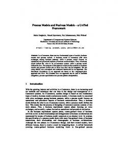
Fig. 2. The relationship between complexity and throughput of our QPSKmodulated G-STSK(2, 2, 2, 4, P ), achieving the maximum diversity order of four, where the parameter P was changed from P = 1 to P = 4.
number of non-zero components in K(i) = [k1 (i), · · · , kQ (i)]T is equal to P . Next, the conditional probability P (Y¯ |K) of the linearized equivalent system model of Eq. (10) is given by 1 exp P (Y¯ |K) = (πN0 )N T
� �� �� � ¯ χK ��2 ��Y¯ − H −
N0
. (11)
Accordingly, the ML detection criterion is formulated as ˆ2 ) = arg max P (Y¯ |K) ˆ1 , B (B
(12)
(B1 ,B2 )
�
�� �� ¯ χK ��2 = arg min ��Y¯ − H (B1 ,B2 ) �� �� 2 Q �� �� �� ¯ � � ¯ � �� = arg min ��Y − kq H χ q �� , (B1 ,B2 ) �� �� q=1
�
(13) (14)
¯ χ. Note that the denotes the qth column of H � � �Q ¯χ computational complexity imposed by calculating kq H
where
¯χ H
q
q=1
q
in Eq. (14) linearly increases with the parameter P , because the number of non-zero elements in kq (q = 1, · · · , Q) is P as mentioned above. More specifically, the computational complexity per bit for the detection scheme of Eq. (14) is evaluated in terms of the number of real-valued multiplications, which may be shown to be 4M N T 2 Q + (4N T P + 2N T )f (Q, P )LP . (15) B Fig. 2 shows the relationship between the complexity and the throughput of our QPSK-modulated G-STSK(2, 2, 2, 4, P ) scheme designed for achieving the maximum diversity order of four, where the parameter P was varied from P = 1 to P = 4. As mentioned in Section II, our G-STSK schemes employing P = 1 and P = Q correspond to the STSK and LDC schemes, respectively. As seen in Fig. 2, the normalized throughput R tends to increase with the value of P at the cost of an increased computational complexity. B. Soft Demodulator Although in Section III-A the optimal ML detector was derived for uncoded G-STSK systems, practical communication systems typically employ a powerful channel coding scheme, such as turbo coding [12]. Therefore, we hereby introduce the soft demodulator
4
of our G-STSK scheme, which can be used for iterative detection assisted by Soft-Input Soft-Output (SISO) decoders. Considering that the equivalent received signal block Y¯ in Eq. (10) conveys channel-encoded binary bits b = [b1 , b2 , · · · , bB ], the resultant extrinsic LLR value Le (bk ) of bit bk for k = 1, 2, · · · , B may be expressed as [1] Eq. (16) as shown in the top of the next page where K1k and K0k represent the sub-space of the legitimate equivalent signals K, which satisfy K1k ≡ {K β1 ,β2 ∈ K : bk = 1} and K0k ≡ {K β1 ,β2 ∈ K : bk = 0}, respectively, while β1 ∈ {1, · · · , 2B1 } and β2 ∈ {1, · · · , 2B2 } are the variables corresponding to the S/P converted B1 and B2 input bits of Fig. 1. Furthermore, Eq. (16) may be readily simplified by the well-known max-log approximation [12], giving rise to
� �� �� ¯ χK ��2 ��Y¯ − H
Le (bk ) =
max − K β1 ,β2 ∈K1k
N0
� �� �� ¯ χK ��2 ��Y¯ − H
−
max − K β1 ,β2 ∈K0k
N0
�
+
�
bj La (bj )
j�=k
�
+
� bj La (bj ) .
j�=k
(17)
IV. DCMC C APACITY In this section we characterize the DCMC capacity [8] of our GSTSK framework. As mentioned above, members of the G-STSK family support many other MIMO arrangements, hence the resultant capacity equation is also applicable to diverse MIMOs. According to [8], the DCMC capacity of our G-STSK scheme using L−PSK/QAM signaling may be derived from that of the discrete memoryless channel as 1 C= T
��
max P (K 1,1 ),···,P (K B1 B2 ) 2 ,2 β
�
· P (K β1 ,β2 ) log2
�
(bits/symbol).
� ,β � β1 2
1 ,β2
�
∞
∞
···
−∞
−∞
P (Y¯ |K β1 ,β2 )
�
P (Y¯ |K β1 ,β2 ) dY¯ P (Y¯ |K β � ,β � )P (K β � ,β � ) 1
2
1
2
(18)
Since Eq. (18) is maximized under the assumption that all the signals K β1 ,β2 are equi-probable, i.e. when we have P (K 1,1 ) = · · · = P (K 2B1 ,2B2 ) = 1/2B , Eq. (18) is simplified to [8] C=
1 T
�
B−
�
×
β1 ,β2
1 B 2⎡
E ⎣log2
⎧ ⎨� ⎩
� ,β � β1 2
exp(Ψ
� � β1 ,β2 β1 ,β2
� ⎫⎤⎞ � ⎬ � )�� K β1� ,β2� ⎦⎠ , ⎭ � (19)
where we have �
�
β ,β ¯ χ(K β ,β − K β � ,β � ) + V¯ ||2 + ||V¯ ||2 . Ψβ11 ,β22 = −||H 1 2 1 2
(20) To be specific, in Fig. 3 we portray the DCMC capacity curves of our QPSK-modulated G-STSK(2, 2, 2, 4, P ) scheme, where P was varied from P = 1 to P = 4. As seen in Fig. 3, upon increasing the SNR value, each capacity curve converged at its attainable normalized throughput R of Eq. (5). Additionally, observe in Fig. 3 that the capacity tended to be increased with the parameter P , although the capacity curves corresponding to P = 3 and P = 4 were found to be almost identical.
Fig. 3. DCMC capacity of the QPSK-modulated G-STSK(2, 2, 2, 4, P ), where P was varied from P = 1 to P = 4.
V. P ERFORMANCE R ESULTS In this section the performance of our G-STSK system is characterized, while comparing the effects of diverse G-STSK parameters. In this contribution, we generated an appropriate dispersion-matrix set capable of achieving a good BER performance for each G-STSK arrangement, which were designed based on the well-known rankand determinant-criterion [1] for the sake of simplicity, although we may readily employ other design criteria, such as the DCMC-capacity maximization technique of [1]. For the sake of saving space, we only investigated the coded GSTSK system, where we considered a serially concatenated threestage turbo codec characterized for example in Section 7.4 of [1]. More specifically, the information bits are firstly channel-encoded by the half-rate Recursive Systematic Convolutional (RSC) code and then interleaved by the first random interleaver Π1 . Next, the interleaved bits are further encoded by the Unity-Rate Convolutional (URC) code and the URC-coded bits are then interleaved by another random interleaver Π2 . Finally, the interleaved bits are mapped to the AEs with the aid of our G-STSK mapping scheme of Fig. 1, in order to generate the space-time codewords S(i) to be transmitted to the receiver. By contrast, the receiver structure is constituted by a threestage iterative detector, where three SISO decoders exchange their extrinsic information in the form of Log-Likelihood Ratios (LLRs). Let us assume that the RSC code is used as the outer code, while considering the amalgamated combination of the URC code and the G-STSK mapper to be the inner code. Fig. 4 shows the EXIT curves of the QPSK-modulated GSTSK(2, 2, 2, Q, P ) arrangements at the SNR of 0 dB, where the parameters (Q, P ) were varied. We also plotted the outer RSC(2,1,2) decoder’s EXIT curve which employed the octal generator polynomials of (3, 2)8 , and the EXIT trajectory associated with the GSTSK(2, 2, 2, 3, 2) scheme, where the interleaver length of both the interleavers Π1 and Π2 was set to 200 000 bits. This is a high interleaver length, which enables a good match between the EXITchart prediction and the Monte-Carlo simulation-based BER results, as detailed in [1]. Furthermore, the corresponding EXIT curves recoded for BLAST and for the Alamouti code were also shown. It can be seen in Fig. 4 that depending on the G-STSK parameters employed, the corresponding inner decoder’s EXIT curve exhibited substantially different characteristics. The area within the open EXITtunnel determines how close the system may operate with respect to the DCMC capacity. Particularly, the inner decoder’s EXIT curves of the G-STSK(2, 2, 2, 3, 2) scheme exhibited the narrowest open tunnel at this SNR point, resulting in a performance which was the
5
�
¯ K β1 ,β2 ∈K1k P (Y |K β1 ,β2 ) · exp
&� j�=k
'
bj La (bj )
�
&� '= Le (bk ) = � ¯ � b L (b ) K β1 ,β2 ∈K0k P (Y |K β1 ,β2 ) · exp j�=k j a j
� �� �� 2 ¯ ��Y¯ −H χK ��
K β1 ,β2 ∈K1k exp −
N0
� �� �� 2 ¯ ��Y¯ −H χK ��
K β1 ,β2 ∈K0k exp −
N0
+ +
� j�=k
� j�=k
� bj La (bj )
�,
(16)
bj La (bj )
we can also introduce a threshold for controlling the computational complexity imposed by the receiver, when appropriately designing the sets of G-STSK parameters configured for near-instantaneously adaptive operation. VI. C ONCLUSIONS
Fig. 4.
EXIT chart of our RSC- and URC-coded G-STSK system.
0
R EFERENCES
10
No. iterations
I
= 0 - 20
-1
10
-2
10
RE B
-3
10
y t i c a p a c
-4
10
-5
C
10
M C D
-6
10
-3
-2
-1
0
1
2
3
4
In this paper we proposed the novel G-STSK architecture, which acts as a unified MIMO framework, including many of the previouslydeveloped MIMO arrangements, such as SM/SSK, LDC, STBC, BLAST and STSK as G-STSK’s special cases. More specifically, based on the G-STSK’s underlying concept, namely that P out of Q pre-allocated dispersion matrices are activated in conjunction with the P classic PSK/QAM symbols, we can strike a flexible tradeoff between the achievable diversity order, throughput as well as computational complexity. Additionally, the unified DCMC capacity was derived for our G-STSK scheme, which also represents the capacity of other diverse MIMO arrangements.
5
SNR [dB]
Fig. 5. Achievable BER performance of our RSC- and URC-coded GSTSK(2, 2, 2, 3, 2) system employing QPSK modulation, where the number of iterations I was changed from I = 0 to I = 20.
nearest to capacity for all the G-STSK arrangements. Furthermore, the Monte-Carlo simulation-based decoding trajectory demonstrated that the EXIT-chart prediction was quite accurate. Finally, Fig. 5 shows the achievable BER performance of our RSC- and URC-coded G-STSK(2, 2, 2, 3, 2) system employing QPSK modulation, achieving a total throughput of R = 1.25 bits/symbol. The number of iterations I between the outer and inner codes was varied from I = 0 to I = 20. As predicted from the EXIT chart of Fig. 4, the corresponding BER curve exhibited an infintesimally low BER at the SNR point of 0 dB. This was within about 1 dB from the SNR corresponding to the DCMC capacity, namely from −1.0 dB. In order to attain an even ‘nearer-to-capacity’ performance, the irregular inner- and outer-code concept [13] can be employed, where a set of EXIT curves corresponding to the diverse G-STSK parameters would allow us to create a narrower EXIT tunnel. However, it may be more practical to adaptively select one of the EXIT curves, in order to maintain an open EXIT tunnel, while increasing the achievable throughput R, depending on the instantaneous SNR. Additionally,
[1] L. Hanzo, O. Alamri, M. El-Hajjar, and N. Wu, Near-Capacity MultiFunctional MIMO Systems: Sphere-Packing, Iterative Detection and Cooperation. John Wiley and IEEE Press, 2009, 714 pages. [2] P. Wolniansky, G. Foschini, G. Golden, and R. Valenzuela, “V-BLAST: An architecture for realizing very high data rates over the rich-scattering wireless channel,” in Proceedings of the International Symposium on Signals, Systems, and Electronics (ISSSE’98), Pisa, Italy, 1998, pp. 295– 300. [3] V. Tarokh, N. Seshadri, and A. Calderbank, “Space-time codes for high data rate wireless communication: performance criterion and code construction,” IEEE Transactions on Information Theory, vol. 44, no. 2, pp. 744–765, 1998. [4] B. Hassibi and B. Hochwald, “High-rate codes that are linear in space and time,” IEEE Transactions on Information Theory, vol. 48, no. 7, pp. 1804–1824, 2002. [5] R. Mesleh, H. Haas, S. Sinanovic, C. Ahn, and S. Yun, “Spatial modulation,” IEEE Transactions on Vehicular Technology, vol. 57, no. 4, pp. 2228–2242, 2008. [6] J. Jeganathan, A. Ghrayeb, L. Szczecinski, and A. Ceron, “Space shift keying modulation for MIMO channels,” IEEE Transactions on Wireless Communications, vol. 8, no. 7, pp. 3692–3703, 2009. [7] J. Jeganathan, A. Ghrayeb, and L. Szczecinski, “Spatial modulation: optimal detection and performance analysis,” IEEE Communications Letters, vol. 12, no. 8, pp. 545–547, 2008. [8] S. Ng and L. Hanzo, “On the MIMO channel capacity of multidimensional signal sets,” IEEE Transactions on Vehicular Technology, vol. 55, no. 2, pp. 528–536, 2006. [9] S. ten Brink, “Convergence behavior of iteratively decoded parallel concatenated codes,” IEEE Transactions on Communications, vol. 49, no. 10, pp. 1727–1737, 2001. [10] R. Heath Jr and A. Paulraj, “Linear dispersion codes for MIMO systems based on frame theory,” IEEE Transactions on Signal Processing, vol. 50, no. 10, pp. 2429–2441, 2002. [11] S. Alamouti, “A simple transmit diversity technique for wireless communications,” IEEE Journal on Selected Areas in Communications, vol. 16, no. 8, pp. 1451–1458, 1998. [12] L. Hanzo, T. Liew, and B. Yeap, Turbo Coding, Turbo Equalisation, and Space-Time Coding for Transmission over Fading Channels. John Wiley and IEEE Press, 2002, 766 pages. [13] N. Wu and L. Hanzo, “Near-capacity irregular-convolutional-codingaided irregular precoded linear dispersion codes,” IEEE Transactions on Vehicular Technology, vol. 58, no. 6, pp. 2863–2871, 2009.