A Unifying Semantics for Sequential Function Charts Nanette Bauer1 , Ralf Huuck2 , Ben Lukoschus3, Sebastian Engell4
3
1 BASF Aktiengesellschaft 67056 Ludwigshafen, Germany
[email protected] 2 National ICT Australia Ltd (NICTA), The University of New South Wales, Sydney, Australia
[email protected] Institute of Computer Science and Applied Mathematics University of Kiel, 24098 Kiel, Germany
[email protected] 4 Process Control Laboratory (BCI-AST) University of Dortmund, 44221 Dortmund, Germany
[email protected]
Abstract. Programmable Logic Controllers (PLC) are widely used as device controllers for assembly lines, chemical processes, or power plants. Sequential Function Charts (SFC) form one of the main programming languages for PLCs and, therefore, the correctness of the PLC software implemented as SFCs is crucial for a safe operation of the controlled process. A prerequisite for reasoning about program correctness is a clear understanding of the program semantics. As we show in this work, this is currently not the case for SFCs. Although syntactically specified in the IEC 61131-3 standard, SFCs lack an unambiguous, complete semantic description. We point out a number of problems and explain how these lead to different interpretations in commercial programming environments. To remedy this situation we introduce a parameterized formal semantics for SFCs including many high-level programming features such as parallelism, hierarchy, actions and activity manipulation. Moreover, we show how to extend the semantics to include time, clocks, and timed actions. The presented semantics is general enough to comprise different existing interpretations while at the same time being adjustable to precisely represent each of them.
1
Introduction
Programmable Logic Controllers (PLCs) are widely used for automation in process industry, transportation and manufacturing. Their hard- and software is defined in the standard IEC 61131. Concerning the software different programming languages are standardized, one of them is Sequential Function Charts (SFC). SFCs are graphical high-level notations for PLC programs. They allow
the decomposition and structuring of program parts including interesting concepts like parallelism, activity manipulation and hierarchy. Moreover, there is the notion of time and timers, which allows to test and reason about the amount of time a program part has been active and to start program parts after a delay or for some limited time only. All these features can, however, again aggravate the understanding of SFCs. As PLC software often performs safety-relevant functions, its formal analysis is crucial, and for this a formal semantics is required. However, the standard only gives an informal description of the semantics of the PLC languages. The semantics of SFCs given in IEC 61131-3 is ambiguous and erroneous, and PLC programming tool developers interpret the ambiguities posed by the standard in different ways, which results in a variety of different tool semantics. Although there exist a few approaches to formalize SFCs [1–3] none of them addresses all of the concepts which are crucial for SFCs, such as parallelism, hierarchy, their action concept, and timing aspects, and none of them considers tool-specific interpretations. To remedy this situation a formal semantic is defined which includes all language concepts and furthermore tool-specific implementations. This semantics makes formal analysis possible and may also be helpful as a unifying basis for further tool developments. The remainder of this work is organized as follows: First we introduce the basic concepts of SFCs informally in Sect. 2. In Sect. 3 we show ambiguities arising from the IEC 61131-3 definitions for SFCs and define a formal syntax and semantics for untimed SFCs which considers these ambiguities by the introduction of adaptable parameters. In Sect. 4 it is shown how this semantics can be augmented to timed aspects. Section 5 shows how the semantics can be adapted to the behavior of different tools. The contribution closes with conclusions given in Sect. 6.
2 2.1
Sequential Function Charts Basic Structure
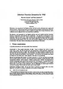
Sequential function charts are defined in [4] as elements of a graphical programming and structuring language for programmable logic controllers. The SFC definitions in IEC 61131-3 (in the following referred to as “the standard”) are based on IEC 60848 [5], which defines the specification language Grafcet. Grafcet in turn is strongly related to Petri nets [6]. Basically, SFCs are transition systems consisting of steps (the locations) and transitions. For every SFC there exists exactly one initial step. Every transition is labeled with an associated transition condition, called guard. Moreover, one or more actions may be associated to each step. Actions are again SFCs or programs in one of the other programming languages proposed by the standard. Since the actions associated to steps can also be SFCs themselves, a concept of hierarchy is provided. An example of a sequential function chart is depicted in Fig. 1.
initial step transition
guard
g1 N
step g2
a1
action qualifier P1 N
action block action name
a2 a3
g3
Fig. 1. Elements of SFCs
The action blocks shown in Fig. 1 are a graphical means to associate actions to steps. An action block consists of an action qualifier, which can be used to specify the activity of the respective action, and the action name. Concerning the action qualifiers defined in the standard, we focus on those without an associated duration of time (considered later in Sect. 4). These are the following: qualifier meaning N S R P1 P0
Non-stored Set or Stored Reset Pulse – rising edge (activation of corresponding step) Pulse – falling edge (deactivation of corresponding step)
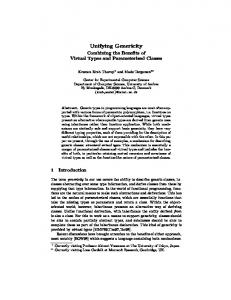
Intuitively, the non-stored actions are always active while control resides in the corresponding step, i.e., as long as it is active. In contrast the stored actions remain active even outside their step of activation until the corresponding reset action is called. The actions with the pulse qualifier are performed only once when entering (P1) or exiting (P0) a step. An SFC does not necessarily have to be a single sequence of steps and transitions. For SFCs we can identify a number of different transition types (cf. Fig. 2). Transition (1) denotes a simple transition between two steps, (2) describes alternative branching, i.e., the choice between several transitions, (3) divergence, (4) convergence, and (5) a simultaneity of both of the latter. In this context divergence means a parallel branching from one step to a set of next steps while convergence means the synchronization of several steps in parallel to a single one. Furthermore, direct combinations of both as depicted in (5) are allowed. Moreover, the standard refers to transitions like the one guarded by g3 in Fig. 1 as loops. From our point of view loops as well as alternative branching belong to the same class, namely (sets of) simple transitions. An additional feature of SFCs is to explicitly assign priorities to alternative branches. This means, when firing transitions the one which has the highest
s1
s3
(1)
s11
s12
s13
s15
s16
g5
g1 s2
s7
g2 s4
g3 s5
g4 s6
g7
g6 s8
s9
(2)
s10
s14
(3)
(4)
s17
s18
s19 (5)
Fig. 2. Basic transition types
priority among the enabled ones will be taken. If there are no priorities given, SFC programming tools often implement the implicit rule that the transitions are ordered “from left to right” in decreasing priority, i.e., in Fig. 2 the transition guarded by g2 has priority over those guarded by g3 and g4 , and the one guarded by g3 has priority over the one guarded by g4 . The basic transition types can be combined into more complex transition structures like in Fig. 1 and Fig. 3. However, there are various combinations which do not seem to make sense, e.g., in the SFC shown in Fig. 3. There we have the transition from s4 to s1 which jumps out of a parallel branch, the converging transition from s2 to s5 , which jumps from one simultaneous branch to another, and the transition from s5 and s6 to s7 , which is a convergence of simultaneous sequences of two steps which are part of an alternative branching starting in step s3 .
? s1 g1
s2
s3
s4
g2
g3 g4
- s5
g5 s6
g6 s7 Fig. 3. Unsafe SFC
Although the standard forbids to use these kinds of “unsafe” or “unreachable” SFCs, it does not give a precise characterization of this phenomenon. For the time being we do not want to pose any explicit restrictions on the SFC syntax. Mainly because we want to allow as much freedom as possible and because there are commercial tools available which “support” SFCs with these kinds of transitions and do simulations on them. Hence, in the following we define a semantics for sequential function charts which can also cope with such ill-formed constructions.
2.2
Ambiguities
The standard defines rules for building an SFC from the aforementioned basic elements and describes how to execute SFCs by giving evolution rules similar to the firing rules of Petri nets. However, execution is only defined on an abstract level not taking into account concrete aspects of program execution. As SFC is a programming language, the exact semantics of execution is of interest and it is therefore important to consider the PLC-specific cyclic execution of SFCs. In every scan cycle first the current input from the environment (i.e., from the sensors of a plant such as pressure or temperature sensors) is read and stored. Then the PLC program is executed based on the stored input, i.e., the actions of the active steps are executed, which may change the output, and afterwards the transitions are taken. At the end of each cycle the output is sent to the environment, i.e., to the actuators of a plant such as valves or motors. Although the semantics of SFCs on an abstract level seems to be quite simple, the exact semantics on an operational level is sometimes far from obvious. Let us have a close look at some key issues.
How to deal with parallelism? In which order are actions of parallel steps executed? Is there any order at all or do we have to cope with non-determinism? As illustrated by the example in Fig. 4 the order of execution makes a difference if the actions read or modify the same variables. Depending on whether executing a1 before a2 or not, the transition guarded with y = 2 is enabled or not.
a0 N x := 0, y := 0
s0 y=0 s1
N x≤1
a1 x := 1
s2
N a2 y := 2x y=2
Fig. 4. In which order are the actions a1 and a2 executed?
The execution order is also not clear if we have more than one action associated to a step. Are they executed from top to bottom or according to a different rule?
SFC0: s0 g1 s1
a1 P1 N SFC1
S P0
a2 a3 g2
Actions : a1: y := x+z a2: x := x+1 a3: z := 1 SFC1: R S
s10
a2 a3
g11
g3 s11
g12
Fig. 5. How to deal with hierarchy?
How to deal with hierarchy of SFCs? Fig. 5 shows a top-level SFC SFC 0 with a second SFC nested in step s1 (SFC 1 ). Has the top-level SFC higher priority, that is, are the actions of the top-level SFC executed prior to the actions of the nested SFC? If we enter s1 in SFC 0 , does the execution order of actions depend on the hierarchy, i.e., do we first execute a1 and then the actions a2 and a3 of SFC 1 ? Can SFC 1 reset a2 or has the top SFC priority and a2 is executed? Which step of the nested SFC will be entered if it is called again? For instance, if we enter step s1 again, do we always activate s10 or is there a notion of history, and the last active step of SFC 1 (which may also be s11 ) therefore gets activated? 2.3
Possible Answers to Ambiguities
The standard does not provide any explicit answer to the questions posed above. For the execution order of actions a comparison of different SFC programming tools of some major PLC vendors [7] yields that there exist various orders on actions, e.g., for one tool actions are executed according to the alphabetic order of action names, for another one by user-defined orders, and so on. However, in no case there is non-determinism. This seems to be reasonable since PLCs are in general deterministic. The semantics defined in the following copes with these different semantics by introducing a parameter for the order of actions. Another parameter is introduced for the order of transitions to reflect priorities if several transitions of an alternative branching are enabled simultaneously.
For the questions concerning history one may deduce from the standard that actions exist globally within the SFC, that means we have a global execution order within the SFC and its nested SFCs. This also means that a reset of an action will also effect the action if it is called within a nested SFC. Furthermore we define that an SFC action may either have or have no history, such that it is either possible to always re-enter in the last active step or always re-enter in the initial step. Finally, there is the question whether it is possible to create algebraic loops, e.g., is it possible that a nested SFC calls the top-level SFC again with a different qualifier? In general this is not forbidden, but in our framework we assume systems without algebraic loops and leave it to the program designer to avoid these. These decisions are the basis for a clear non-ambiguous syntax and semantics of SFCs which is presented next.
3 3.1
Formal Untimed Syntax and Semantics Syntax of SFCs with Actions
SFCs (or PLC programs in general) have different types of variables, such as input variables, output variables, and local variables. The values of the variables may belong to different data types such as Boolean or integer. The valid variable and data types are regulated by the standard IEC 61131-3, already mentioned above. We abstract from these different variable and data types by simply saying that a PLC has a set of variables X which may have different values. To describe the values of all variables we use the notion of a state: Definition 1 (State). A state is a type-preserving function σ assigning a value to each variable in X. Let Σ be the set of all states. A state (i.e., the values of the variables) can be modified by state transformations. In the standard different types of programming languages are defined for such state transformations. We abstract from these languages by simply saying that a state transformation is a function that transforms a given state into another state. Here state transformations are deterministic; in non-deterministic languages a state is transformed into one of several possible successor states. Definition 2 (State transformation). A state transformation is a function f : Σ → Σ. Let F be the set of all state transformations. Each step of an SFC is labeled with a (possibly empty) set of action blocks, which are pairs of action names and qualifiers. We associate either a unique state transformation or a call of a nested SFC with an action name. Moreover, we simply say actions when in fact referring to action names. Definition 3 (Action name, action block). An action name is an identifier for either a state transformation f ∈ F or an SFC S (defined below). An action
block is a pair (a, q) consisting of an action name a and an action qualifier q, where q ∈ {N, S, R, P0, P1}. Let B denote the set of all action blocks. For any action block b ∈ B we denote by ba the projection to the action name and by bq the projection to the qualifier. We define a guard as a Boolean expression reasoning about variables and step activities. Syntactically, the activity of step si is expressed by the term si .X. Definition 4 (Guard). A guard g is a Boolean expression over variables and step activities. We denote the set of all guards by G. Moreover, we need an order on actions as well as on transitions. These allow to determine in which order actions are executed and which transition will be taken if several are in conflict with each other. In conflict means that more than one alternative transition is enabled. Hence, the order on transitions rules out any non-determinism. Let SFC be the set of sequential function charts, which are defined next. Definition 5 (SFC). A sequential function chart (SFC) is a 9-tuple S = (X, S, A, s0 , T, block ,