A Unitary Approach to Speed Sensorless Induction Motor Field Oriented Drives Based on. Various Model Reference Schemes. G.Griva*, F.Profumo**, C.Ilas***, ...
A Unitary Approach to Speed Sensorless Induction Motor Field Oriented Drives Based on Various Model Reference Schemes G.Griva*, F.Profumo**, C.Ilas***, R.Magureanu***, P.Vranka****
* **
*** ****
Dipartimento di Ingegneria Elettrica, Politecnico di Torino, C.so Duca degli Abruzzi 24, 10129, Torino, Italy, Fax: +39-11-564.7199, Tel.: +39-11-564.7159 Dipartimento di Ingegneria Elettrica, UniversitA di Bologna, v.le Risorgimento 2,40196, Bologna, Italy, Fax: +39-51-644.3588, Tel.: +39-51-644.3580 Dept. of Electrical Engineering, Polytechnic of Bucharest, Spl. Independentei 313, 77206 Bucharest, Romania, Fax: +40-1-3 120412, Tel.: +40- 1-4.lOO.4OO Dept. of Electrical Engineering, University of Miskolc, Egyetemavaros, 35 15 Miskolc, Hungary, Fax: +36-46-361.740, Tel.: +36-46-365.111
Abstract
In this paper a unified approach to different schemes based on Model Reference Adaptive Systems (MRAS) for speed sensorless Field Oriented Controlled (FOC) induction motor drives is presented. In the last few years several solutions belonging to this category have been proposed. They have different configurations and distinct adaptation mechanisms, properly chosen in each case. A new, general adaptation mechanism is presented in the paper. It is derived according to Popov hyperstability theory and is valid for any adaptive system belonging to this category, no matter what its configuration is. A general demonstration for the stability of these adaptive systems is given, using the Lyapunov stability theorem. This unitary approach allows an easier comparison and classification of different particular solutions. The paper focuses on two of the most used configurations. In the first solution the reference model is the motor and the adaptive one is a linear state observer, which, in particular, is an Extended Luenberger Observer (ELO). In the second solution, both models are rotor flux (or other quantities) estimators and this scheme is usually known as Model Reference Adaptive System (MRAS). The performance of these two schemes is analyzed starting from their configuration and then compared by simulations and experimental results. introduction
Several schemes have been proposed during the last few years for shaft sensorless Field Oriented Control (FOC) of induction motors. The advantages of using sensorless drives are clear: the mech'mic setup and maintenance are easier, since no shaft sensor is required, the system becomes less sensitive to the environmental noise and also the costs can be drastically reduced (mainly for low power applications). Among these schemes, many are based on the idea of comparing the outputs of two models: one that does not contain the speed (the Reference Model, RM) and another that does (the Adaptive Model, AM). The difference between their outputs is due to an eventually incorrect speed value, and hence an adaptation mechanism is used to adjust this 0-7803-3544-9196$5.00 0 1996 IEEE
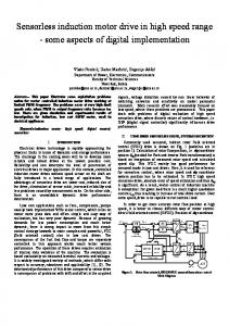
parameter in the AM. A block diagram for such structure is presented in Fig.1. Many solutions with small differences have been presented, depending on the two models structures and on the implementation of the adaptation mechanism, but two of them seem to be the most attractive. In the first one the RM is the motor and the AM is an Extended Luenberger Observer (ELO). In the second one, both models are rotor flux (for example) estimators and is usually known as Model Reference Adaptive System (MRAS). The general structures are presented in Fig.2, and Fig.3.
.
, (
I
Adaptation
L
Fig.1. Adaptive system: structure based on the adaptation mechanism for the speed estimation.
Determination of the Adaptation Mechanism
In general, the RM and the AM can be described by the following equations: (RM):
X=Ax+Bu y=cx
(AM):
i = 2 +BU 4: =C?
+ ~ ( -fy)
The matrices A, B, and C describe the induction motor voltage equations, considering the stator current as the model output, while L is the observer gain matrix. For the adaptive model the matrix has been introduced instead of A because it contains the estimated speed. This is the most general situation of all the adaptive schemes based on an adaptive mechanism, because of the observer structure, which is the most complex.
i 594
ii
a : +
FOC
-A:
*
Using Popov terminology [5], let us consider the block described by Ne,). The associated inputoutput integral index is:
Induction nonlinear
CRPWM Inverter
(RM)
tl
rl(to,tl) =Reje;(t)p(t)dt t0
where: e:
4-
FOC
A;-+ I
-fft,
Induction
CRPWM Inverter
= [e:
O OI A necessary condition for the hyperstability of this block is:
Fig.2. Speed sensorless FOC induction motor drive, with EL0 speed estimation.
tl
q(O,t,)= je:(t)p(t)dt2-y2(0) I I
for any input-output combination and a given positive constant $0). Replacing p with its expression and considering the error between the two matrices as being exclusively caused by the error between the real and the estimated speed: A-A Fig.3. Speed sensorless FOC induction motor drive, with MRAS speed estimation. Denoting the error between real and estimated state by e, = x - 2 , the error dynamic equation can be obtained:
It describes a linear system (A+LC, I, C) connected by feedback with a nonlinear one, given by the function #ey). This nonlinear system has the output error e, as input and gives (A - A)? as output. Considering that the feedback is negative, the overall block diagram is shown in Fig.4, where p denotes - (A - A)? .
=(U,
-Gr)Aer
i.e.
yields:
The condition (2) is respected i f T 6ir = G r = KjeyA,?dt
The stability of the general adaptive system thus obtained can be proved by taking the Lyapunov function:
Application of the General Adaptation Mechanism to Particular Systems
Fig.4. Structure of the system describing the error dynamic equation.
The application of the general adaptation mechanism to particular systems can be done by replacing the general quantities in Eq.3 by particular ones, specific for each system. For the EL0 scheme this means:
i 595
~
Simulation Results
:1 0
Which means:
The EL0 and MRAS speed sensorless schemes have been tested in simulation for a closed loop speed control system of a field oriented induction motor drive. The induction motor rated quantities and parameters are shown in the Appendix. Different tests have been simulated to compare the two schemes performance. Fig.5 shows the results obtained for no-load starting conditions (0 to 1000 rpm speed reference step), followed by a torque step (at the rated value) after 2 seconds, in the ideal case, i.e. in the following conditions:
- ideal inverter (the votage references are applied directly -
to the motor terminals); parameters tuning; absence of noise on the measured stator currents and voltages.
The estimated speed is obtained using the particular forms of the general adaptation mechanism given by Eq.4 (for the EL0 scheme) and Eq.5 (for the MRAS scheme). Fig.6 shows the low speed performance, obtained for (4) no-load starting conditions (low reference speed step), followed by a torque step (at half the rated value), in the .2 same ideal case as in Fig.5. where K >O is an arbitrary constant and o = 1 . Thus, the rotor resistance detuning effect has been tested LsLr and the results are shown in Fig.7, where the speed For the MRAS scheme, considering the RM outputs as reference and the load torque are the same as in Fig.5, the real quantities, and the AM outputs as the estimated the inverter is ideal and there is no measurement noise. quantities, it yields: The real rotor resistance has been set 20% higher than the rated one. Finally, Fig.8 shows the influence of the measurement noise (speed reference and load torque as in Fig.5) in tuned parameters conditions, with PWM inverter. A white noise has been superimposed on the measured stator currents and voltages. It can be seen that the EL0 scheme performance is The general adaptation mechanism becomes: generally better than the M U S scheme performance. In the MRAS scheme there is a karger speed error in all the test conditions (especially when the load is applied to the motor shaft), even in the ideal case. Furthermore, in the low speed r