A Version Support Model for. Architecture Based Design Process. M. Luciana Roldán, Silvio Gonnet, Horacio Leone. CIDISI, Universidad Tecnológica Nacional.
M. L. Roldán et al./Proc. of Argentine Symposium on Software Engineering (2005) 19-33
19
A Version Support Model for Architecture Based Design Process M. Luciana Roldán, Silvio Gonnet, Horacio Leone CIDISI, Universidad Tecnológica Nacional INGAR, Universidad Tecnológica Nacional, CONICET Avellaneda 3657, 3000, Santa Fe, Argentina {lroldan, sgonnet, hleone}@ceride.gov.ar
Abstract. Software architecture based design demands new tools for managing the different versions generated during the design process. Based in a generic process versioning administration model, a model for capturing and managing the products of the software architecture design process is presented. Thus, the proposed model enables the designer to trace such design process and its resulting products, a first step towards computational environments that support architecture based design. The model is defined using a hybrid approach that combines object-oriented technology, first order logic, and situation calculus. The situation calculus is used to formally express the existence of an object and its structure in a given state of a design process.
1
Introduction
Software Architecture Design is still considered as a difficult, challenging problem, because it usually involves a complex process of exploration, evaluation, and composition of design alternatives [1, 2]. Increasingly, modeling languages [3], methods [4, 5, 6], and computer-aided tools [2, 7] are available to face these complex activities. They focus basically on assisting a designer in generating a software architecture design to satisfy a set of requirements. During the Software Architecture Design Process (SADP), several different design products are generated (transformed and refined), which have different abstraction levels of the architecture being designed. However, most design knowledge still rests in the minds of experienced designers, and is lost as time goes by. Consequently, there is a need for tools able to capture and manage this process. By counting on such tools, both the tracking and tracing of the SADP and the analysis of its rationale would be possible. In this way, the expert’s knowledge could be captured, thus providing the foundations for learning and training activities and for future reuse. In order to develop a support environment with the aforementioned characteristics, this contribution introduces a model that captures and traces the products of SADP. Its goals are to make explicit the states of SADP and how they were obtained. The model is based on a generic Process Version Administration Model (PVAM) [8]. PVAM provides mechanisms for capturing and managing versions generated during the course of an engineering design project. It is summarized in the next section. After that, in Section 3, an extension of PVAM is
20
M. L. Roldán et al./Proc. of Argentine Symposium on Software Engineering (2005) 19-33
described. The extension focuses on the products and operations of SADP. The proposed model is illustrated in Section 4 by designing a monitoring system for an industrial process. Finally, conclusions and future research guidelines are discussed.
2
An Integrated Model for Design Process Capture and Management
The proposed scheme considers the SADP as a sequence of activities that operate on the products of the design process, which are called design objects. Typical design objects are architectures of the software being designed, specifications and scenarios to be met. Naturally, these objects evolve as the SADP takes place, giving rise to several versions. In order to maintain these versions, the previously proposed PVAM [8] is considered. The class diagram illustrated in Fig. 1 introduces its main concepts. PVAM represents a design object at two levels, the repository and the versions’ level (Fig. 1). The repository level keeps a unique entity for each design object that has been created and/or modified due to model evolution during a design project. This object is regarded as a versionable object (o). On the other hand, the versions’ level keeps the different versions of each design object, which are called object versions (v). The relationship between a versionable object o and one of its object versions v is represented by the version relationship. Therefore, a design object keeps a unique instance in the repository and all the versions it assumes belong to the versions’ level. At a given stage during the execution of a design project, the state assumed by the set of relevant design objects, from now on called model version, supplies a snapshot description of the state of the design process at that point. Each transformation operation applied to a model version incorporates the necessary information to trace a model evolution. This information is represented by history relationships between the object versions to which the operation is applied and the ones arising as the result of its execution (Fig. 1). This model was completely axiomatized using the situation calculus [9] and first order logic. PVAM is discussed in [8]. This contribution only presents the model extension needed to support the SADP. Activity
Versions predecessor * Version * successor predecessor ModelHistory ModelVersion successor History
1..*
1..* belong
* ObjectVersion
* AttribValue
1..* version
version
Repository Domain object origin objectType ModelingConcept * * VersionableObject * instance container * * end * part Association * associationType
Fig. 1. Process Version Administration Model
* attributeType
* Attribute DomainRelationship
M. L. Roldán et al./Proc. of Argentine Symposium on Software Engineering (2005) 19-33
21
A new model version mn is generated when an activity a is executed. An activity a is materialised by a sequence of operations φ and the new model version mn is the result of applying such sequence φ to the components of a previous model version mp. This model evolution is posed as a history made up of discrete situations. The situation calculus is adopted for modelling such version generation process. Therefore, the new model version mn is achieved by performing the following evaluation: apply(φ, mp) = mn. The primitive operations that were proposed to represent the transformation of model versions are add, delete, and modify. By using the add(v) operation, an object version that did not exist in a previous model version can be incorporated into a successor. Conversely, the delete(v) operation eliminates an object version that existed in the previous model version. Also, if a design object has a version vp, the modify(vp, vs) operation creates a new version vs of the existing design object, where vs is a successor version of vp. Thus, an object version v belongs to a model version that arises after applying the sequence of operations φ to model version m, if and only if one of the following conditions is met: i) v is added when the new model version is created by means of an add or modify operation (Expression 1); or ii) v already belonged to the previous model version m (belong(v, m)) and it is not deleted when φ is applied to it (Expression 2). (∀φ, v, m) (add(v) ∈ φ ∨ (∃vp) modify(vp, v)) ∈ φ ⇒ added(v, apply(φ, m))
(1)
(∀φ, v, m) (delete(v) ∈ φ ∨ (∃vs) modify(v, vs) ∈ φ) ⇒ deleted(v, apply(φ, m))
(2)
From these definitions, and by using the format of successor state axioms proposed by [9], a formal specification of the cases in which an object version belongs to a model version is presented. In expression 3, the predicate belong(v, m) is true when object version v belongs to model version m. From this expression, the object versions belonging to a model version can be determined. Then, it is possible to reconstruct a model version mi+1 by applying all operation sequences from the initial model version m0. (∀φ, v, m) belong(v, apply(φ, m)) ⇔ (belong(v, m) ∨ added(v, apply(φ, m))) ∧ (¬deleted(v, apply(φ, m)))
(3)
With the aim of capturing the versions generated during a SADP, PVAM must be extended according to the particular design objects produced by that process. For this purpose, the Domain Package, shown in Fig. 1, must be extended. Particularly, the ModelingConcept class, which represents the type of design objects, must be specialized with concepts of the SADP domain. Furthermore, the different operations that are applied to the distinct design objects must be defined. The following section defines such extension.
22
3
M. L. Roldán et al./Proc. of Argentine Symposium on Software Engineering (2005) 19-33
Extending PVAM for Architecture Based Design Process
As pointed out in the previous section, it is necessary to have a model of the products of SADP. These products are taken from the Attribute-Driven Design Method (ADD) proposed at [4, 5, 6], and the architectural description language ACME [3]. The class diagram shown in Fig. 2 introduces these concepts and their relationships. This model is implemented by the instantiation of the classes of Domain package (Fig. 1). The classes presented in Fig. 2 are going to be instances of ModelingConcept and their properties are going to be instances of Attribute. Finally, the relationships of Fig. 2 will be instantiated from DomainRelationship in Domain package. Requeriment
Functional Requirement
Quality Requirement
Responsibility
Quality Scenario
System
Assessment
Component
Style
Component Type
Port
Property Type
Property
Attachment
Constraint Connector Type
Role Connector
Fig. 2. Domain Model for Architecture Based Design
The ADD method is based on a recursive decomposition process where architectural patterns (or styles) are chosen at each stage to fulfill a set of quality scenarios. Then, component and connector types provided by the pattern are instantiated and functionality is allocated to them. The input to ADD is a set of requirements (functional and quality requirements). The quality requirements are expressed as a set of system specific quality scenarios, and the functional requirements are translated into a set of responsibilities [6]. Quality scenarios and responsibilities can be delegated to other components when the original component is refined. When the method iteration is finished, the designer verifies scenarios and set an assessment. In ADD, the different model versions are represented by using three types of views: component (or logic view), concurrency, and deployment view. Only the component view is considered in the scope of this work in order to describe the architecture. Accordingly, ACME [3] has been chosen as the architectural description language. ACME defines a component as a computational element and data store of a system. A component may have multiple interfaces, each of which is termed port. The
M. L. Roldán et al./Proc. of Argentine Symposium on Software Engineering (2005) 19-33
23
connectors represent interactions among components and have interfaces that are defined by a pair of roles. The systems comprise components and connectors, establishing attachments between roles and ports. In Fig. 2, the attachment concept is not considered as a modeling concept but as a relationship. Moreover, ACME proposes elements to document extra-structural properties of a system’s architecture, as Properties. Furthermore, it is possible to attach constrains to design elements. With the aim of providing a more powerful language, ACME defines component, connector, and properties type building blocks. On the basis of these modeling concepts, it is possible to define Families or Styles. They are defined by a set of property, component, and connector types and a set of constraints. On the other hand, the primitive operations add, delete and modify are not enough to capture and trace a SADP execution. Then, PVAM must be extended in terms of the suitable operations for the software architecture design domain, like the ones listed in Table 1. These operations can be based on the primitive operations and expressed in terms of added and deleted predicates previously defined in Expressions 1 and 2. Table 1. Possible Operations for the Software Architecture Design Domain Basic Operations addComponent addConnector addFunctionalRequirement addPort addProperty addQualityRequirement addResponsibility addRole
deleteComponent deleteConnector deleteFunctionalRequirement deletePort deleteProperty deleteQualityRequirement deleteResponsibility deleteRole
addScenario
deleteScenario
addTypeComponent
deleteTypeComponent
addTypeConnector
deleteTypeConnector
Special Operations
Styles/Mechanisms application
refineComponent
applyIntermediaryBlackboard
refineResponsibility
applyControlLoop
delegateResponsibility
applyRuleEngine
delegateScenario
applyClientServer
verifyScenario
applyPoolOfConnections
This operations range from the most basic to the most complex ones: i) Basic: operations that allow creating and deleting basic design objects (like components and connectors) (Fig. 3); ii) Special: more complex operations that involve object refinement or delegation (Fig. 4); iii) Styles/Mechanisms application: these operations generate a new set of design objects which have a configuration based on an architectural style; or even if they do not modify the model structure, they affect some design objects properties (Fig. 5, 6).
24
M. L. Roldán et al./Proc. of Argentine Symposium on Software Engineering (2005) 19-33
addComponent(s,c, lResps,lPorts) add(c) for each r in lResps addResponsibility(c,r) for each p in lPorts addPort(c, p) add(rel(s, c))
deleteComponent(s, c) lPorts = getPorts(c) for each p in lPorts deletePort(c, p) end for delete(rel(s,c)) delete(c)
addConnector(s, cn, lRoles, lPorts) add(cn) i = 0 for each r in lRoles addRole(cn, r) add(rel(lPorts(i), r)) i = i+1 end for add(rel(s, cn))
deleteConnector(s, cn) lRoles = getRole(cn) for each r in lRoles delete(rel(getPort(r),r) delete(r) end for delete(rel(s,cn)) delete(cn)
addRole(cn, r) add(r) add(rel(cn, r))
deleteRole(cn, r) // role deletion implies // elimination of complete // connector deleteConnector(cn)
addPort(c, p) add(p) add(rel(c, p))
deletePort(c, p) // port deletion implies // deletion of connector //attached to it deleteConnector(getConnector( getRol(p))) delete(rel(c, p)) delete(p)
addResponsibility(c, r) add(r) add(rel(c, r))
deleteResponsibility(c, r) delete(rel(c, r)) delete(r)
addScenario(s, c, qr) add(s) add(rel(c, s)) add(rel(c, qr))
Fig. 3. Specification of Basic Operations
Fig. 3 presents functional specifications for some of the basic operations defined in Table 1. The other operations are defined in a similar way, but they are not shown due to shortage of space. These operations are defined in terms of primitive operations as add(c), and non-primitive ones, as addPort(c, p), which is also defined in Fig. 3. For example, the addComponent(s, c, lResps, lPorts) operation allows adding a component c to a system s. As seen in Fig. 3, this operation is carried out by a series of operations. First, a version of component c is added (add(c)). After that, a set of responsibilities (specified by list lResp) and ports (detailed by list lPorts) are inserted. Finally, a relationship between the new component c and an existing system s is included. This last operation is performed by the add primitive operation (add(rel(s, c))). Note that each of the aforementioned operations can be translated into a sequence of primitives operations add, delete, and/or modify that are applied to a
M. L. Roldán et al./Proc. of Argentine Symposium on Software Engineering (2005) 19-33
25
previous model version, which results in a new model version. From this, it is possible to express these operations in terms of added and deleted predicates introduced in Expressions 1 and 2. For illustration purposes, let us consider again the addComponent(s, c, lResps, lPorts) operation. If it is applied to a model version m, then a version of a component c, will belong to the successor model version (apply(φ, m)), as it is defined in Expression 4. (∀ φ, s, c, lResps, lPorts, m) addComponent(s, c, lResps, lPorts) ∈ φ ⇒ added(c, apply(φ, m)) ∧ added(rel(s,c), apply(φ, m)) ∧ ((∀ r ∈ lResps) added(r, apply(φ, m)) ∧ added(rel(c,r), apply(φ, m))) ∧ ((∀ p ∈ lPorts) added(p, apply(φ, m)) ∧ added(rel(c,p), apply(φ, m)))
(4)
Similarly to Expression 4, the definition of new operations allows enlarging the set of operations. This can be done without modifying the successor state axiom (Expression 3). It is important to highlight that the operations implementation has to contemplate a series of basic validations in order to maintain the model consistence, as well as other validations derived form the imposed constraints related to certain component types or styles of the model. The precondition for applying the addComponent operation is specified in Expression 5, where the poss(op, m) predicate expresses that an operation op is applicable to a given model version m. (∀ s, c, lResps, lPorts, m) poss(addComponent(s, c, lResp, lPorts), m) ⇔ belong(s, m) ∧ ¬ belong(c, m) ∧ (∀ r ∈ lResps) ¬ belong(r, m) ∧ (∀ p ∈ lPorts) ¬ belong(p, m)
(5)
Similarly to definition of basic operation, it is possible to define the special operations. Fig. 4 presents some examples. A functions with ‘?’ symbol at the end indicates that it is an interactive function, thus, the user is asked about how to proceed. The delegateResponsibility(c1, c2) operation enables delegating a responsibility of component c1 to component c2. Thus, if a given responsibility is assigned to a component c1 in a model version m and a delegateResponsibility(c1, c2) operation is included in the sequence of operations applied to m, then the resulting model version shows that the responsibilities delegated to c2 will not be assigned to c1. In a similar way, the operation delegateScenario proceeds. The refineComponent(c, lComps, llPorts, llResps, lConns, llRoles, llAtts) operation, another example of special operation (Fig. 4), decomposes a component c into one or more components given by the list lComps. The ports and responsibilities of the new components are given by the lists llPorts and llResps, respectively. Furthermore, a set of connectors among the new components is added. These connectors are specified by lConns whose roles are given by the list llRoles and the attachments by the list llAtts. The operations that apply an architecture style refine a preexistent component with a new set of components and connectors that are instantiated from a preexisting
26
M. L. Roldán et al./Proc. of Argentine Symposium on Software Engineering (2005) 19-33
style. They interact with the designer asking for the responsibilities and scenarios delegation, as well as connectors mapping between external components and refined components. For example, if the Client-Server style is defined, the applyClientServer(c) operation refines the component c in two new components: Server and Client. These new component have some predefined responsibilities and ports. Furthermore, a connection between them that fulfils with properties imposed by the style is added. Finally, the designer is asked for responsibilities delegation from original component to Server and Client components. delegateResponsibility(c1, c2) lResps = getResponsibility(c1) for each r in lResps if (delegate?(c2, r)) delete(rel(c1, r)) add(rel(c2, r)) end if end for
delegateScenario(c1, c2) lScens = getScenario(c1) for each s in lScens if (delegate?(c2, s)) delete(rel(c1, s)) add(rel(c2, s)) end if end for
refineComponent(c, lComps, llPorts, llResps , lConns, llRoles, llAtts) i = 0 for each cc in lComps lr = llResps(i) // cc responsibilities listi lp = llPorts(i) // cc ports listi addComponent(getSystem(c),cc,lr,lp) i++ end for i = 0 for each cn in lConns lr = llRoles(i) // cn roles listi la = llAtts(i) // port list which should attach cn roles addConnector(getSystem(c), cn, lr, la) i++ end for // delegate scenarios and responsibilities to // new components (interactive) for each cc in lComps delegateScenario(c, cc) delegateResponsibility(c, cc) end for // create new connections between internals components // and external components (interactive) lp = getPorts(c) for each p in lp np = PortMap?() r = getRol(p) delete(rel(p, r)) add(rel(np, r)) end for deleteComponent(getSystem(c),c)
Fig 4. Specification of Special Operations
Another applyStyle operation is defined in Fig. 5. In this case, the applyControlLoop operation is specified. This style proceeds from the process control paradigm and defines the architecture to activate various monitoring policies when different events coming from sensors are produced [10]. The monitoring policies may
M. L. Roldán et al./Proc. of Argentine Symposium on Software Engineering (2005) 19-33
27
in turn produce other events or actions in response to predefined situations. Note that this operation can be considered as a specialization of refineComponent operation. Here, the knowledge on how to proceed in the refinement is given by the control loop style and it is not given as argument. Therefore, a series of addComponent operations is performed. The addComponent(s, {Diagnosis, TDiagnosis}, [P1,P6]) operation indicates that a component and two ports must be created. The component is called Diagnosis, whose modeling concept is TDiagnosis, an instance of TypeComponent (see Fig. 2), and the ports are denominated P1 and P6. applyControlLoop(c) s = getSystem(c) addComponent(s,{Diagnosis, TDiagnosis}, [P1,P6]) addComponent(s,{PolicyManager, TPolicyManager}, [P2,P3]) addComponent(s,{Reactor, TReactor}, [P4, P5]) addConnector(s,{CDgnPMgr,TCDgnPMgr},[R1,R2],[P1,P2]) addConnector(s,{CPMgrRct,TCPMgrRct},[R3,R4],[P3,P4]) delegateScenario(c,Diagnosis) delegateScenario(c,PolicyManager) delegateScenario(c,Reactor) delegateResponsibility(c,Diagnosis) delegateResponsibility(c,PolicyManager) delegateResponsibility(c,Reactor) // Set mappings between previous connector and new components lp = getPorts(c) for each p in lp np = PortMap?(p) // Ask the user the port to map r = getRol(p) delete(rel(p, r)) add(rel(np, r)) end for deleteComponent(s, c)
Fig 5. Specification of applyControlLoop Operation
Another style operation described here is applyIntermediaryBlackboard (Fig. 6). It uses a tactic consisting of inserting an intermediary between directly communicated components [4]. The objective is to break the dependence chain between modules, avoiding ripple effects on related components. The pursued quality attribute is Modifiability. Particularly in this case, the component acting as intermediary between data producer and consumers is a Blackboard component [4, 11], which sends notifications to subscribers when the interest data change, and has responsibilities in inserting, updating and deleting data. A special connector called Bus is also used. ACME supports neither n-ary connectors nor direct connection between components. Therefore, it is necessary to employ a component for representing it, along with a set of auxiliary binary connectors [12]. Furthermore, the Bus component has implicit responsibility for recording the components subscribed to specifics events, and inform registered components of certain event occurrence. The operation arguments are: i) Component list to attach Bus (lComps1); ii) Component list to directly attach BlackBoard (lComps2); iii) Connector list to be deleted because they are not necessary in the new configuration (lConns). The operation adds a bus component (type TBus), a blackboard component (type TBlackBoard) and a connector between them. After that, each component listed by lComps1 is attached to a new port of
28
M. L. Roldán et al./Proc. of Argentine Symposium on Software Engineering (2005) 19-33
the Bus, and each component included on lComps2 is associated to a new port of the BlackBoard. Finally, the connectors specified on lConns are deleted. applyIntermediaryBlackboard(lComps1, lComps2 ,lConns) s = getSystem(lComps1(0)) addComponent(s, {Bus,TBus},[PBB]) addComponent(s, {BlackBoard, TBlackBoard}, [PB]) addConnector(s, {CI,TBusBlackboard}, [RCI1, RCI2]) add(rel(PBB, RCI1)) add(rel(PB, RCI2)) i= 0 For each c in lComps1 addPort(Bus, pbi) addPort(c, pci) addConnector(s, {Cnx,TBusInter},[Rx1,Rx2]) add(rel(pbi, Rx1)) add(rel(pci, Rx2)) i= i + 1 end for i= 0 For each c in lComps2 addPort(BlackBoard, pbbi) addPort(c, pci) addConnector(s, {Cnx,TBBAux},[Rx1,Rx2]) add(rel(pbbi, Rx1)) add(rel(pci, Rx2)) i= i + 1 end for For each cn in lConns deleteConnector(s, cn) end for
Fig 6. Specification of applyIntermediaryBlackboard Operation
4
Case Study: Monitoring System for an Industrial Process
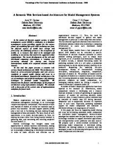
The case study describes the design of a monitoring system for an industrial process (see Fig. 7). Monitoring activities are focused on the two core distillation columns: an extractive distillation column and a solvent stripping one, working together in a highly integrated manner. The system should monitor: • control loops and temperature sensors, by continued acquisition of real-time process data, tracking set-point values, alarm conditions and outputs of valves, and comparing them with “normal” patterns behavior. • process state, using real-time process data previously processed (e.g. averaged or integrated) in combination with expert knowledge in order to maintain process stability and performance • flowrate sensors and validate material balances. This task should be carried out using cumulative values of flowrate data for sensor reconciliation and detection of solvent accumulation in the circuit.
M. L. Roldán et al./Proc. of Argentine Symposium on Software Engineering (2005) 19-33
29
In order to meet all these functional requirements, the system should be connected to input and output devices. Input devices allow the system to get the real time data from the process equipment and output devices are used by the system to inform the plant operator about process anomalies, like: solvent inventory buildup, sensor fault, abnormal process pattern, etc. Input-Output Devices
Fig 7. Monitoring System for an Industrial Process
The main functions considered in designing the monitoring system include: administration of users (process operator, plant supervisor, etc.) and permissions, configuration of input/output devices, priority-based event management, process diagnosis, specification of warning and process protective actions. In addition, all monitored information and process operator interactions should be recorded for future use. One of the key aspects of the system is its reactivity, which is how the system recognizes certain events and triggers corrective or warning messages. The model evolution for the proposed case is analyzed in the next sections. For reasons of space, some intermediate design versions will not be shown, and the associated rationale will not be detailed for all executed steps. Also, the last version obtained here can be further improved, applying additional operations. The goal of this case study is to show how the extended PVAM could support the SADP. 4.1 The First Model Version The first model version resulting from the SADP is shown on Fig. 8. It is the result of applying a sequence of operations φ1 to the initial model version. The initial model version is an empty one. The sequence φ1 includes the addSystem(MonitoringSystem) operation, which adds a first object version of MonitoringSystem at the version level and a versionable object on repository. Also, a series of addQualityRequirement and addFunctionalRequirement operations are carried out when φ1 is performed. These functional and quality requirement, are associated to MonitoringSystem. These are the quality scenarios to be considerated: i) a new type of sensor is attached, and the system has to get it without other modifications (ScModif1); ii) if an abnormal situation is detected by sensors, the system should start corrective or alarm actions in response to it in less than 1 second (ScPerf1); iii) a process operator should very easily configure 70% of system functionality (ScModif2); iv) the average time taken to provide a response to any kind of event should not be longer than 5 seconds
30
M. L. Roldán et al./Proc. of Argentine Symposium on Software Engineering (2005) 19-33
(ScPerf2); v) new events can be defined, and they may change their priorities and carried information. These modifications should have minimal impact on the system, while the level of response of the system to events should be maintained (ScPerfModif1); vi) in order to incorporate personalization or deal with new devices, new configuration rules can be added, (ScModif3). Finally, the component Monitor is added by the addComponent( MonitoringSystem, Monitor, {RAdmin1, RConfig1, REvent1, RDiag1, RConfig2, RStore1},{}) operation. The responsibilities are derived from the system functional requirements and quality scenarios. The scenarios are derived from the system quality requirements. The responsibilities associated to Monitor component are: Administration of users and permissions (RAdmin1); Input/Output devices configuration (RConfig1); Priority based event management (REvent1); Diagnostic (RDiag1); Warning and protective actions specification (RConfig2); Register and store every monitoring information for future uses (RStore1). During the SADP these object versions can be modified, eliminated, refined (giving rise to new objects), delegated, etc., resulting in the various model versions. Applied Operations: φ1= { addSystem, addFunctionalRequirement, addQualityRequirement , addQualityScenario, addComponent, addResponsibility}
FuncReq1
Modifiability
MonitoringSystem
Performance
FuncReq2
SCPerf1
FuncReq2
SCPerf2
Monitor
RAdmin1
SCModif1 RConfig1
SCModif2
REven1
RConfig2 RDiag1
RStore1
SCModif3
SCPerfModif1
Fig. 8. A First Model Version resulting from the Software Architecture Design Process
4.2 An Intermediate Model Version i In Fig. 9, we can observe the model version i where the main component Monitor belonging to a previous model version has been refined in four components: Control&Diagnosis (with responsibilities in priority based event management, protective actions execution, warning launch, input/output devices configuration); UserInterface (with responsibilities related to user interaction issues: set parameters values, show information, rule administration); SensorActuatorLayer (with
31
M. L. Roldán et al./Proc. of Argentine Symposium on Software Engineering (2005) 19-33
responsibilities like sending out commands to actuators, receiving information from sensors); Configuration. The responsibilities are delegated to the new components, and Monitor component has been deleted.
MonitoringSystem
RAdmin1
REvent1
SCPerf1
UserInterface
RDiag1
SCPerf2 RConfig1 RStore1
Control&Diagnosis
RConfig2
Configuration
Applied Operattions: φi+1= {applyControlLoop, refineResponsibility, addConnector}
SCModif2
Resp1
SCModif1
Resp2
SensorActuatorLayer
SCPerfModif1
View of Model Version i
SCModif3 RPMgr6 RPMgr5
RPMgr4 RPMgr3
MonitoringSystem
RPMgr2
C&Dv,1
SCPerf1
P1C&Dv,1
PolicyManager
RConfig1
SCPerf2
Model Version i ∩ Model Version i + 1
Configuration
P2C&Dv,1 RReact5
P3C&Dv,1 applyControlLoopHistory Model Version i + 1
RAdmin1
UserInterface
RPMgr1
Model Version i
>
Reactor
RReact4
RDiag1.1 RDiag1.2 RDiag1.3
Diagnosis
RReact3 RReact2 RReact1
SCModif1
P1Reactv,1
RConfig2
SCModif2
SCPerfModif1 RSA1 RSA2 RSA3
SensorActuatorLayer
SCModif3
View of Model Version i + 1
P2PMgrv,1
Reactv,1
P1PMgrv,1 PMgrv,1
P1Diagv,1
Diagv,1 version
version
Repository
C&Do P3C&Do
P2C&Do
Diago
P1C&Do
PMgro Reacto
P1Diago P2PMgro P1Reacto
P1PMgro
Fig. 9. Evolving the Products of the Software Architecture Design Process
From this model version, the designer can continue with the SADP, choosing refine Control&Diagnosis component by applying the applyControlLoop operation. This operation creates three new components: Diagnosis, PolicyManager, and Reactor. The applyControlLoop operation asks the necessary information for delegating responsibilities, and for reconnecting previous connections to the new configuration (see Fig. 5 for applyControlLoop specification).
32
M. L. Roldán et al./Proc. of Argentine Symposium on Software Engineering (2005) 19-33
Fig. 9 shows a partial view of the Version and Repository levels from which model version views can be inferred. This partial view is focus on the version of Control&Diagnosis evolution to a set of versions of components and connector due to applyControlLoop operation. This is traced by an instance of the history link (Fig. 1) which associates the previous versions with the successor versions. Additionally, other operations were applied on the model version i to obtain the model version i+1 that are not illustrated on Fig. 9 at version and repository levels. One of them arises due to the need of associating PolicyManager and Configuration components, so a new connection and their roles objects are added, applying addConnector operation. Using again operation addConnector, a new connection between PolicyManager and SensorActuatorLayer is added. It enables PolicyManager to receive information from and to send information to SensorActuator (see Fig. 9, View of model version i+1). It is important to note that the proposed extension of PVAM enables applied operations on SADP´s products (Fig. 2) to be captured. For example, responsibilities are refined using refineResponsibility operation. The RDiag1 responsibility (Fig. 9, view of model version i) was refined on the following responsibilities: i) listening notifications of situations coming from SensorActuator (RDiag1.1); ii) getting devices information (RDiag1.2); iii) probing device (RDiag1.3) (Fig. 9, view of model version i + 1).
5
Conclusions
The model proposed in this paper, an extension of PVAM, captures the operations that generate each design product during the SADP. Furthermore, it also offers an explicit mechanism to manage the different model versions generated during the SADP. Thus, it allows the tracing of the SADP and its resulting products, setting the grounds for learning and future reuse of the design process. This is a fundamental step towards the development of computational tools to support the SADP and to guide designers in the different activities of a design project. Situation calculus, the formal background of the framework, let us represent the activities carried out during a SADP, and therefore, it enables the designer to get a better understanding of the information on how the various design objects (systems, components, connectors, functional requirements, quality requirements, quality scenarios, assessment, so on) have been obtained. Thus, the history of operations performed on versions of design objects can be kept. Also, this conceptual framework provides the foundations for the proposal of formal means for detecting potential conflicts. The framework could incorporate extensions to the Domain package, integrated to the version administration model, defining others characteristics not included by ADD or ACME. Furthermore, this contribution uses an operational perspective where design decisions can be modeled by means of design operations. This approach is employed in other contributions [2, 5]. The structure of the conceptual framework permits easily definition of specific design operations, like applyControlLoop and
M. L. Roldán et al./Proc. of Argentine Symposium on Software Engineering (2005) 19-33
33
applyIntermediaryBlackboard, without modify the successor state axiom (Expression 3). Similarly, other design operations, like the ones defined by [5], can be specified.
References 1.
Tekinerdogan, B.: Synthesis-Based Software Architecture Design. PhD Thesis, University of Twente, Enschede, The Netherlands (2000) 2. Diaz Pace, A.: A Planning-Based approach for the exploration of Quality-Driven design alternatives in Software Architectures. Tesis Doctoral, Universidad Nacional del Centro de la Provincia de Buenos Aires, Facultad de Ciencias Exactas (2004) 3. Garlan, D., Monroe, R. T., Wile ,D.: Acme: Architectural Description of Component-Based Systems. Foundations of Component-Based Systems, Gary T. Leavens and Murali Sitaraman (eds.), Cambridge University Press (2000) 47-68 4. Bass, L., Clements, P., Kazman, R.: Software Architecture in Practice: Second Edition. Addison-Wesley (2003) 5. Bass, L., Klein, M., Bachmann, F.: Quality Attribute Design Primitives and the Attribute Driven Design Method. 4th International Workshop on Product Family Engineering. Bilbao, Spain, (2001) 3-5 6. Bachmann, F., Bass, L., Chastek, G., Donohoe, P., Peruzzi, F.: The Architecture Based Design Method. Technical Report CMU/SEI-2000-TR-001 (2000) 7. Bachmann, F., Bass, L., Klein, M.: Preliminary Design of ArchE: A Software Architecture Design Assistant. Technical Report CMU/SEI-2003-TR-021 (2003) 8. Gonnet, S.: Un modelo integrado para la captura y administración del proceso de diseño. Tesis Doctoral, Universidad Nacional del Litoral, ISBN 987-43-9244-4 (2003) 9. Reiter, R.: Knowledge in Action: Logical Foundation for Describing and Implementing Dynamical Systems. The MIT Press (2001) 10. Shaw, M.: Beyond Objects: A Software Design Paradigm Based on Process Control. Tech. Report CMU-CS-94-154, Carnegie Mellon University, Pittsburgh (1994) 11. Garlan, D., Shaw, M.: An Introduction to Software Architectures. Advances in Software Engineering and Knowledge Engineering (1993) 12. Di Nitto, E., Rosenblum, D. S.: Exploiting ADLs to SpecifyArchitectural Styles Induced by Middleware Infrastructures. In Proceedings of the 21st International Conference on Software Engineering, Los Angeles, CA (1999)
Acknowledgments This work has been supported by CONICET, Universidad Tecnológica Nacional and Agencia Nacional de Promoción Científica y Tecnológica (PICT 12628). Authors gratefully acknowledge help received from these institutions.