Article
A Vibrotactile and Plantar Force Measurement-Based Biofeedback System: Paving the Way towards Wearable Balance-Improving Devices Christina Zong-Hao Ma 1,2 , Anson Hong-Ping Wan 1 , Duo Wai-Chi Wong 1 , Yong-Ping Zheng 1 and Winson Chiu-Chun Lee 1,3, * Received: 29 September 2015; Accepted: 10 December 2015; Published: 15 December 2015 Academic Editor: Oliver Amft 1
2 3
*
Interdisciplinary Division of Biomedical Engineering, The Hong Kong Polytechnic University, Hong Kong, China;
[email protected] (C.Z.-H.M.);
[email protected] (A.H.-P.W.);
[email protected] (D.W.-C.W.);
[email protected] (Y.P.-Z.) Rehabilitation Engineering Research Institute, China Rehabilitation Research Center, Beijing 100068, China Institute of Active Ageing, The Hong Kong Polytechnic University, Hong Kong, China Correspondence:
[email protected]; Tel.: +852-2766-4942; Fax: +852-2334-2429
Abstract: Although biofeedback systems have been used to improve balance with success, they were confined to hospital training applications. Little attempt has been made to investigate the use of in-shoe plantar force measurement and wireless technology to turn hospital training biofeedback systems into wearable devices. This research developed a wearable biofeedback system which detects body sway by analyzing the plantar force and provides users with the corresponding haptic cues. The effects of this system were evaluated in thirty young and elderly subjects with simulated reduced foot sensation. Subjects performed a Romberg test under three conditions: (1) no socks, system turned-off; (2) wearing five layers of socks, system turned-off; (3) wearing five layers of socks, and system turned-on. Degree of body sway was investigated by computing the center of pressure (COP) movement measured by a floor-mounted force platform. Plantar tactile sensation was evaluated using a monofilament test. Wearing multiple socks significantly decreased the plantar tactile sensory input (p < 0.05), and increased the COP parameters (p < 0.017), indicating increased postural sway. After turning on the biofeedback system, the COP parameters decreased significantly (p < 0.017). The positive results of this study should inspire future development of wearable plantar force-based biofeedback systems for improving balance in people with sensory deficits. Keywords: falls; postural stability; balance; sensory augmentation; wearable device; plantar force measurement; biofeedback; elderly
1. Introduction Falls and consequent injuries have been and are major public health problems all over the world [1]. About 50% of young adults with long-term neurological conditions have experienced falls [2]. Approximately 30%–50% of people aged 65 or older living in the community, residential care facilities and nursing homes experience falls every year [1,3]. The incidences of falls and consequent injuries have been increasing along with the aging population [4]. The burden of the consequence of falls is heavy. They are associated with significant mortality and morbidity, reduced life span, reduction of quality of life, and huge hospitalization costs [5]. Risk factors of falls have been studied extensively. Balance and gait disorders are the second leading cause of falls, just coming after accidents [6]. Multiple factors contributed to balance and gait disorders, including aging, sensory abnormalities, musculoskeletal disorders, neurologic disorders, cardiovascular diseases, infectious and metabolic
Sensors 2015, 15, 31709–31722; doi:10.3390/s151229883
www.mdpi.com/journal/sensors
Sensors 2015, 15, 31709–31722
diseases, and psychiatric conditions [7]. In clinical practice, static balance is usually trained before dynamic balance. Various balance training devices have been developed to improve static balance. Some of them induce physical challenges to balance by providing unstable support surface. Examples of these devices included wobble boards, ankle discs, balance sandals, foam pads, balance trampolines and tilting platforms, as reviewed in [8]. The balance challenges offered by these devices might not be suitable to people with moderate or severe balance disorders [8]. Some biofeedback systems, as reviewed in [9], have been developed in an attempt to improve the balance of patients with various types of balance disorders. The underlying principle of these devices is to improve balance by supplementing and enhancing somatosensory input [9]. Some systems measure the changes of plantar forces using a floor-mounted force-plate [10–14]. Some other systems mount inertial motion sensors (accelerometers and gyroscopes) on the user’s lower trunk or head to capture torso or head tilt in mediolateral and anteroposterior directions [15–23]. The sensors are wired to computers, which interpret body postures by processing the plantar force and body motion signals and send the corresponding control signals to a display (visual feedback) [24–27], an audio device (audio feedback) [13,14,28], or some type of vibrator (vibrotactile feedback) [16,19,21–23]. The feedback devices provide users with additional augmented sensory information on their body sway. Many biofeedback systems described in the literature were however only designed for use in laboratories and clinics. Patients would normally need to go to the clinics/laboratories to perform the balance training, which usually lasts for at least 2 weeks, as reviewed in [9]. In-home balance training contributes to the continuity and adherence of training [29]. Good compliance rates were achieved in home-based balance training programs [30,31], however, whether the training device is convenient to use could affect the compliance in patients. Large sensing/feedback elements and the need of a wired connection to a computer would discourage people from using the systems at homes. Making the biofeedback systems portable and convenient to use is necessary to allow them to be used at home. While current advanced technology enables microprocessors to be small and lightweight, which allows them to be wearable, little attempt has been made to turn hospital training biofeedback systems into wearable devices. Thin-film, in-shoe force sensors are ideal for the wearable purpose. They are obviously smaller and lighter than any force plates. In addition, it is possible for the thin-film sensors together with the associated electronic components for power supply, force analysis, and data transmission to be attached to the shoes. The replacement of inertial motion sensors with in-shoe force sensors would reduce the total weight of electronic components to be worn on the upper body. While some mobile in-shoe force measurement systems have been used to measure plantar pressure distribution with success as shown in [11,12,32–34], those devices did not provide real-time feedback of the changes in plantar forces to the users. In addition to force sensors, some studies have attached vibrators to the insoles [11,12,33]. Those vibrating insoles delivered stochastic resonance sub-threshold vibrations to the plantar surface of heel and the metatarsal heads upon floor contact, which was found to improve plantar sensation and balance [11,12,33]. However, the vibrating insoles led to pain and discomfort since the vibrators had to be made of rigid steel which produced excessive pressure on the metatarsal heads and heels [32]. With current wireless data transmission technology, consideration can be given to positioning the vibrators on other areas of the body while wirelessly maintaining the sensor connections. The parameters accessing center of pressure (COP) excursions, which include mean distance and range, have been commonly used to evaluate postural stability during standing [35]. The ability to maintain good stability while standing still is a key indicator of fall risks [36]. Generally, increased COP movements are interpreted as an overall deterioration of postural stability [37], although a previous study found that other factors like anxiety could also increase of the COP displacements [38]. There was also evidence suggesting that better static balance performance is associated with better dynamic balance [35,39].
31710
Sensors 2015, 15, 31709–31722
The objectives of this paper are: (1) to present a wearable biofeedback system, which measures and analyzes the changes in plantar forces and wirelessly sends control signals to vibrators located on the trunk and (2) to report the findings of an experiment conducted to evaluate the effects of the use of this system on static balance, assessed by measuring the COP movements of young and elderly people whose plantar tactile sensory input was experimentally reduced. This paper will also discuss some possible approaches for making the wearable device able to provide real-time postural feedback in dynamic situations. The ultimate goal is to pave the way towards the development of a wearable device which could improve balance in daily living. 2. Experimental Section 2.1. Participants A convenience sampling approach was adopted to recruit thirty healthy subjects (including fifteen elderly adults aged over 65 years and fifteen young adults aged between 18 and 35 years). The young subjects were university students, and the elderly subjects were attendees at a local senior-citizen college. The sample size (a total of thirty subjects) produced a statistical power of 0.8, assuming a medium effect size of 0.5 and two-sided significant level of 0.05 on a two-way mixed-design ANOVA. Table 1 summarizes the subject information, including age, gender, height and weight. The subjects were fully independent, living in a community-based setting, and were capable of ambulation without assistive devices. Subjects with any neurological or vestibular disorders, diabetes, severe cardiovascular or pulmonary diseases, previous history of foot injury, foot deformity, amputation of the lower limbs, inability to attend the necessary re-evaluations, or inability to follow the instructions and procedures of the research protocol were not included in the study. This study was registered on the Chinese Clinical Trial Registry (ChiCTR-IPB-15006530, http://www.chictr.org.cn/ showprojen.aspx?proj=11141) and the Hong Kong Clinical Trial Registry (HKCTR-1853, http://www.hkclinicaltrials.com/). Ethical approval was granted from the authority of local university (Application Number: HSEARS20140211002). All participants signed an informed consent form after receiving oral and written descriptions of the research and the experimental procedures prior to the experiments. The subjects were aware that they could stop their participation if they encountered any kind of discomfort during the experiments. Table 1. Subject Information. [Mean ˘ SD]
Older Subjects (n = 15)
Young Subjects (n = 15)
Age (years) Gender Height (cm) Weight (kg)
70.1 ˘ 3.7 6 females and 9 males 160.6 ˘ 7.6 61.7 ˘ 11.4
26.7 ˘ 2.9 7 females and 8 males 167.6 ˘ 5.8 61.4 ˘ 11.2
2.2. The Vibrotactile Biofeedback System The vibrotactile biofeedback system consisted of two separate components of: (1) a plantar force acquisition unit and (2) a vibration feedback unit. The plantar force acquisition unit consisted of six thin-film force sensors (A301, Tekscan Co., Ltd, South Boston, MA, USA), a microprocessor unit (ATMEGA328P, Atmel Co., Ltd, San Jose, CA, USA), a wireless transmitter module (HC-05, HC Information Tech. Co., Ltd, Guangzhou, China), and a rechargeable lithium-ion battery (FLB-18650-3.0, UltraFire Co., Ltd, Shenzhen, China). The vibration feedback unit consisted of four vibrators (XY-B1027-DX, Xiongying Electronics Co., Ltd, Shanghai, China), a wireless receiver module (HC-05, HC information Tech. Co., Ltd.), and a rechargeable lithium-ion battery (FLB-18650-3.0, UltraFire Co., Ltd.). A total of six thin-film force sensors (25.4 mm ˆ 14 mm ˆ 0.203 mm, sensing area 9.53 mm diameter each) were attached to a pair of flat insoles with adhesive tapes. A series of insoles (2 mm thickness) with different sizes were manufactured by a certified orthotist using medium firm 31711
Sensors 2015, 15, 31709–31722
Sensors 2015, 15, page–page
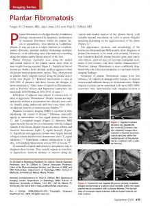
(30–35 ShoreCo. A Hardness) (EVA, Foot Footcare & Products Co.each) Ltd, & Products Ltd, Hongethylene-vinyl Kong, China).acetate Four vibrators (10Specialist mm diameter × 2.7 mm height Hong Kong, China). Four vibrators (10 mm diameter ˆ 2.7 mm height each) were mounted at the were mounted at the anterior (the manubrium level), posterior (the first thoracic level), left anterior (theand manubrium level), posterior (the first thoracic level),byleft (acromion) and right (acromion) (acromion) right (acromion) side of subject’s upper trunk adhesive tapes (Figure 1). Except side of subject’s upper trunk by adhesive tapes (Figure 1). Except for the force sensors, electronic for the force sensors, all electronic components in the plantar force acquisition unit wereallfastened to components in the plantar force acquisition unit were fastened to the lateral side of the lower the leg the lateral side of the lower leg by an elastic strap. The plantar force acquisition unit acquired by andata elastic The plantar acquisition unit acquired force data the foot soles and force at strap. the foot soles and force delivered appropriate processedthe signals to theatvibration feedback delivered appropriate processed signals to the vibration feedback unit via the Bluetooth communication unit via the Bluetooth communication protocol. The vibration feedback unit activated the vibrators protocol. vibration feedback activated the vibrators based on processed vibrating signals. based on The the processed vibratingunit signals. The vibration frequency andthe strength of the vibrator were The vibration frequency and strength of the vibrator were 220 Hz and 1 G, respectively, which 220 Hz and 1 G, respectively, which were found to be highly recognizable by humans [40]. were Both found to befrequency highly recognizable by humans [40]. Both10sampling and transmission rate were were sampling and transmission rate were Hz. Thefrequency force sensors and vibrators 10 Hz. Theby force and wereforce powered by the batteries thevibration plantar force acquisition powered the sensors batteries invibrators the plantar acquisition unit andinthe feedback unit. unit and the vibration feedback unit. Rechargeable batteries with a capacity of 3000 mAh used, Rechargeable batteries with a capacity of 3000 mAh were used, which enabled the entirewere system to which enabled the entire function continuously forsystem 24 h. to function continuously for 24 h. Excluding the the rechargeable rechargeable batteries, batteries, the the dimensions dimensions of of the the plantar force acquisition unit and Excluding plantar force acquisition unit and vibration feedback unit were 4.0 cm ˆ 1.5 cm ˆ 1.7 cm, and 4.5 cm ˆ 2.2 cm ˆ 2.0 cm, respectively. vibration feedback unit were 4.0 cm × 1.5 cm × 1.7 cm, and 4.5 cm × 2.2 cm × 2.0 cm, respectively. The The entire biofeedback system weighed than with theplantar plantarforce forceacquisition acquisitionunit unit weighing weighing entire biofeedback system weighed lessless than 200200 g, g, with the 75 g and the vibration feedback unit weighing 78 g (including the high-capacity rechargeable batteries). 75 g and the vibration feedback unit weighing 78 g (including the high-capacity rechargeable batteries).
Figure 1. The vibrotactile system, consisted of a plantar force acquisition unit, a vibration feedback Figure 1. The vibrotactile system, consisted of a plantar force acquisition unit, a vibration feedback unit, and six six force force sensors sensors attached attached to to aa pair pair of of flat flat insoles. insoles. unit, four four vibrators vibrators and
Force sensors were located at the heels, as well as the first and fifth metatarsal heads to monitor Force sensors were located at the heels, as well as the first and fifth metatarsal heads to monitor the subjects’ postural sway. The force sensors located at the first metatarsal head and the heel were the subjects’ postural sway. The force sensors located at the first metatarsal head and the heel were used to detect the degree of anteroposterior body sway, and the force sensors located at the left and used to detect the degree of anteroposterior body sway, and the force sensors located at the left and right fifth metatarsal heads were used to detect the degree of mediolateral body sway. The right fifth metatarsal heads were used to detect the degree of mediolateral body sway. The anatomical anatomical locations of heel, the first and fifth metatarsal heads were verified by a certified orthotist. locations of heel, the first and fifth metatarsal heads were verified by a certified orthotist. Baseline Baseline readings were first collected while each of the subjects stood still with eyes-closed for 90 s in readings were first collected while each of the subjects stood still with eyes-closed for 90 s in three three repeated trials. The forces detected at each sensor across the 90 s in three test trials were repeated trials. The forces detected at each sensor across the 90 s in three test trials were averaged, averaged, respectively. The averaged values measured at each sensor were then multiplied by 110%, respectively. The averaged values measured at each sensor were then multiplied by 110%, which were which were used to define the thresholds of allowable anteroposterior and mediolateral postural used to the thresholds ofof allowable anteroposterior mediolateral postural swaytested for each sway fordefine each subject. A series threshold-defining ratiosand (100%, 110%, and 120%) were in subject. seriesand of threshold-defining ratios (100%, 110%, and 120%) were tested in oursway. pilot study, our pilotAstudy, the ratio of 110% produced the best outcomes in reducing postural and the ratio of 110% producedvibrating the best outcomes in reducing postural sway. Four vibrators providing stimulations were attached to the anatomical landmarks at Four vibrators providing vibrating stimulations were attached to the anatomical landmarks the the anterior (the manubrium level), posterior (the first thoracic level), left (acromion) and at right anterior (the manubrium level), posterior (the first thoracic level), left (acromion) and right (acromion) (acromion) sides of upper trunk, which corresponded to anterior, posterior, left and right postural sway. Once the detected forces exceeded the preset thresholds, full magnitude of vibrations would 31712
4
Sensors 2015, 15, 31709–31722
sides of upper trunk, which corresponded to anterior, posterior, left and right postural sway. Once the detected forces exceeded the preset thresholds, full magnitude of vibrations would be evoked at the corresponding vibrators. No vibrators were activated if the subjects’ measured forces were below the thresholds. 2.3. Experimental Design and Procedures All subjects were explained how the biofeedback system functioned prior to the experiments. They were informed that the vibration of each vibrator corresponded to one particular directional (forward, backward, left and right) body sway. They were instructed to move toward the opposite direction of the vibrator that had been activated. During the practice period, the subjects were instructed to incline forward, backward and laterally to experience the vibrations in four different directions to ensure that they understood the function of this system and were capable of using the fed back vibrations as a balance aid. The subjects were given 10 min to become familiar with the new biofeedback system. During the experimental period, a Romberg test was conducted to assess balance control [41]. When performing the Romberg test, the subjects were instructed to stand quietly on a force platform with feet together, with the arms crossed resting on opposite shoulders and eyes closed for 90 s for each trial. Such a balance test method and duration has high test-retest reliability [35]. Balance was evaluated under three experimental conditions: (1) without socks and the biofeedback system turned-off (condition 1); (2) wearing five layers of socks and the biofeedback system turned-off (condition 2); and (3) wearing five layers of socks and the biofeedback system turned-on (condition 3). Commercially available socks (Baleno Co. Ltd., Hong Kong, China) was used to simulate reduced plantar sensory input [42,43]. Mechanoreceptors at the plantar surface detect changes in plantar pressure distribution resulting from body motion, and initiate postural reflexes which help prompt the human body to more stable postures [44]. Previous studies have pointed that aging, diabetic malletis, and wearing socks reduced the cutaneous sensation of the plantar surface of the feet, and consequently led to balance disorders [42,43,45]. The socks were 1.6 mm thick, and made of 80.6% cotton, 16.7% polyamide and 2.7% Spandex. Each subject was randomly assigned to one of all possible sequences of three test conditions. Each test condition was repeated three times consecutively for each subject. Between two conditions, the subject was given a 10-min rest to eliminate any possible effect of fatigue. If the subject verbally reported any kind of discomfort during the experiment, the experiment would be stopped with the situation being recorded. 2.4. Outcome Measures A force platform (OR6, Advanced Mechanical Technology, Inc., Watertown, MA, USA) was used to measure the relative location of COP signals to the coordinate origin of the force platform. The COP displacements were computed by the Nexus 1.8.1 software (Vicon Motion Systems Ltd., Oxford, UK), and then used to calculate the COP-based parameters using Microsoft Excel. Based on the computed changes of locations of COP, the (1) mean distance (mm); (2) root mean square distance (mm); (3) the 95% confidence circle area (mm2 ); (4) the 95% confidence ellipse area (mm2 ); (5) planar diameters (mm); and (6) range in anteroposterior (AP) and mediolateral (ML) directions (mm) were calculated [37]. A 5.07/10 g Semmes-Weinstein monofilament (Connecticut Bio-instruments Inc., Bronx, NY, USA) was used to assess the plantar touch-pressure sensation of the feet with and without wearing the socks, which followed the standard testing procedures as specified in [46]. The dominant side was chosen for the testing, and determined by documenting the preferred leg for kicking a football [47]. The subjects were instructed to seat in a chair with their feet resting comfortably on a platform with their legs straight. Two applications and one sham application of monofilament pressing were performed at the plantar surface of the hallux, the first and fifth metatarsal heads. At each site, the monofilament was pressed vertically to the skin surface and bowed for at least 1 s. The testing consequences of three
31713
Sensors 2015, 15, 31709–31722
different sites and two different types of applications were randomized for each subject. The subjects were instructed to respond “yes/no” after each application. Scores were graded from 0 to 3 based on number of correct answers after three applications at each testing site [46]. The higher score of the monofilament testing represented the better sensation. The monofilament testing was performed on all subjects by the same examiner. 2.5. Statistical Analysis Data analysis was performed using Statistical Package for Social Science (SPSS, version 21.0, IBM Corporation, Armonk, NY, USA). Descriptive analysis included mean and standard deviation values for demographic data. Wilcoxon Signed-Ranks Test was used to compare the monofilament score with and without wearing the socks. Two-way mixed-design ANOVA was used to assess if there were significant differences in all COP parameters (1) among the three different experimental conditions pooling all 30 subjects (effect of conditions, within-subjects effect); (2) between young and elderly subject groups pooling data of all three experimental conditions (effect of subject groups, between-subjects effect); and (3) among the three experimental conditions and the two subject groups (intervention effect). If the ANOVA indicated a significant difference, paired t-tests with Bonferroni corrections were used to perform multiple pair-wise comparisons among the three experimental conditions in elderly and young subject groups as well as combined, and independent-samples t-tests were performed to assess if there were significant differences between the young and elderly subject groups in each of the three experimental conditions. Further analysis regarding the degree of changes in postural sway upon using socks and biofeedback system was conducted by calculating the percentage differences in all recorded COP parameters between condition 2 and 1, as well as condition 3 and 2. Independent-samples t-tests were performed to assess if the percentage differences were significantly different between the young and the elderly subject groups. The level of significance was set at 0.05. Bonferroni corrections were performed to adjust the level of significance to 0.017 when performing multiple pair-wise comparisons. 3. Results and Discussion 3.1. Results As shown in Table 2, the average monofilament scores decreased significantly from 2.9 to 1.1 among elderly subjects (condition 2 vs. 1, p < 0.001), and decreased significantly from 3.0 to 1.0 among young subjects while wearing five layers of socks compared with the conditions of not wearing socks (condition 2 vs. 1, p < 0.001). Table 2. Comparison of monofilament scores with and without wearing socks. Monofilament Scores (Mean ˘ SD) Elderly Subjects (n = 15) Young Subjects (n = 15) Position
Without socks
With socks
p-value
Position
Without socks
With socks
p-value
Hallux 1st metatarsal head 5th metatarsal head Average
3.0 ˘ 0.0 2.9 ˘ 0.3 2.7 ˘ 0.8 2.9 ˘ 0.4
1.1 ˘ 0.4 1.0 ˘ 0.0 1.0 ˘ 0.0 1.0 ˘ 0.1