EXTERNAL. DATA. CREATOR. AND INTERFACE .... International Federation of Robotics, Robotics Newsletter, No 7, March, 1993. 4. O'Brien, J. B., Training ...
Automation and Robotics in Construction XI D.A. Chamberlain (Editor) © 1994 Elsevier Science B.V. All rights reserved.
239
A "virtual reality" type simulation system for construction automation system development R. R. Wakefield and J. B. O'Brien Department of Engineering Construction and Management School of Civil Engineering, The University of New South Wales PO. Box 1, Kensington, NSW, Australia
Abstract This paper discusses the creation of virtual reality tools for the detailed planning of construction activities. The development and operation of a prototype interactive construction machine simulator is detailed. A description is then given of the extensions being made to the prototype system to create a generalised construction simulator with advanced visualisation features. Applications of the generalised simulator in construction systems design and automation planning are discussed.
1. INTRODUCTION "Virtual reality" (VR) is a concept that is currently very much in vogue. However what the term "VR" might mean varies widely. To some people VR just a matter of computer graphics "hype", to others VR may be just a simple extension of existing man-machine interface studies. To still others VR may represent a totally new "science fiction" type interaction wherein a person enters Into a fully realistic yet artificial "mind space". In this new world the person can interact - in a full physical and sensory sense - with the environment to do basically everything they could do in the real world. Within the confines of this paper, however, and within the context of the creation of immediately useful tools for the detailed planning of construction activities, we will adopt neither of these two extremes of definition. Instead we will define VR as the process of creating a high quality computer based analogue of a physical system and providing highly intuitive interfaces to a user such that the user might interact with the analogue system under real time operating conditions to discover new knowledge or to acquire new skills. To create these types of computer system, sophisticated information supply to the human, through high quality computer based graphical image synthesis technology and acoustic and kin aesthetic feedback must generally be provided. In terms of the engineering utility of a VR type system, apart from the obvious qualities of the high-technology input-output interfaces and the speed of computational processes, the most important matter is the quality of the central analogue system itself Crude analogues of systems may be provided - as in the analogues of systems used in many video and arcade games or else high fidelity models (in the engineering modelling sense) may be developed as for example in the use of training of pilots for the space shuttle re-entry procedure.
240
To be useful in the construction engineering and robotics system planning context, high engineering-fidelity models are essential. The difference between a simple graphic artist's or animator's view of a construction process and the views that will be described later in this paper is that in the latter a full "engineering-physics" model of the construction process is used. When an operator moves a control, the artificial universe he is interacting with must react exactly - spatially and temporally - as it would do in real life. In these authors view, the central problem in terms of the creation of the "VR construction site" lies not in the computer technology of the display or processing systems but rather lies in the difficulty of development of suitably accurate and computation ally tractable engineering physics models of the construction process. The need for such models and the difficulty of building them has been hinted at in speculations of some earlier writers [1]. These modelling problems become especially difficult where large terrains and complex activities upon these terrains have to be modelled [2]. Further major complications exist where there is physical interaction between machines and their environment with resultant changes in state of the environment. Under such true interaction conditions a dynamic temporal model of the state of the environment as well as of the state of the machine has to be maintained. In the field of manufacturing robot research, VR and advanced simulation ideas have reached a high stage of development [eg. 3]. Unfortunately this work is of limited use to construction engineers since the en vironment is typically highly structured and generally invariant. In addition the robot is fixed in position and is not subject to deflection under load or foundation movement. Weather conditions and other features also do not figure in the factory situation and normally operations are supported by indexed or deterministic, rather than stochastic or variable episodic, material import and export processes. As well comprehensive, closed form mathematical models of the machines and their dynamics are available. Such models are not possible for most common forms of construction machine. 2. THE AIM OF THIS PAPER The aim of this paper is to present - as a form of paradigm for future construction engineering VR-systems - the development and operations of a full-engineering physics based, intuitively interfaced, real time, complex environmentally interactive construction machine simulation system. The system had to confront the full realities of modelling a living construction technology and building in the physics of complex (extant) site machines and the variable operational characteristics of different forms of machine such as to make the whole a useful day to day tool for the construction training industry. Presentation of this work as a fully developed case study will, it is hoped, illustrate to others the nature of the work entailed and the complexity and feasibility of current VR type technology as it applies to construction operations planning and automation systems design and validation. The work discussed is not presented as representative of what the technology can ultimately accomplish but rather as a first - proof of concept - step along a route that will undoubtedly be developed further by future researchers. The particular system that will be described in this paper relates to the problems of modelling the activities of heavy construction plant as it interacts with its environment. This work was done within the context of development of a low-cost general purpose simulator
241
for construction machinery operator training purposes. 3. A PROTOTYPE SIMULATION SYSTEM First efforts in applying simulation technology to the training of earth moving plant operators in the Australian construction industry were made approximately a decade ago [4]. It was however, recognised at the time that the cost of developing such simulators was prohibitive. This was due, in the main, to the cost of the computer hardware necessary to meet the real-time performance requirements of an advanced simulator [5]. In recent times computer performance and costs have changed dramatically. In late 1992 the development of an industrial-grade plant operator training simulator was proven to be commercially feasible. As a proof of this feasibility a simulator project was developed as a joint venture between a team from the School of Civil Engineering at UNSW and the Tasmanian Building and Construction Industry Training Board. The aim of the project was to create a hydraulic excavator simulator suitable for training novice operators and to test it in service. 3.1. Initial investigations and design The first stage of the project was a comprehensive review of available technology to ensure that the computation speed and data transfer problems that arise in the creation of a real-time simulator could be adequately handled. The computer systems investigated ranged from PCs with accelerators, through transputers to high end workstations. Investigations were concentrated on CPU performance, graphics performance, operating system characteristics, expandability, connectability and cost. The most important consideration was the ability of the system to produce three dimensionally realistic images at real-time rates. The specific workstation chosen was a Silicon Graphics Iris Indigo R3000 workstation with an Elan graphics system. The Elan system is a hardware based graphics accelerator with 4 geometry engines, which supplements the graphical capabilities of the basic computer. A decision was made at this stage of the project, to perform all numerical modelling necessary for the simulator operation on a 486 PC. This meant that the bulk of the computational load, arising from the detailed engineering modelling, was removed from the graphics workstation. The workstation is dedicated to the production of high quality 3D images which are critical to the integrity of the simulator from an operator's point of view. 3.2. The computational model The simulator is based on a mathematical model developed on the 486 PC which performs all Calculations relating to the state of the system. The model contains integrated representations of the excavator controls; the prime mover of the excavator; the excavator hydraulics and power transmission; and the excavator structure. Information relating to the machine behaviour and position as well as its environmental interactions are calculated and Provided to the graphics computer in real-time. The mathematical model, as developed, is general in nature and with appropriate data changes can model any hydraulic excavator. The user can specify details of the excavator structure, power system, hydraulic system and controls.
242
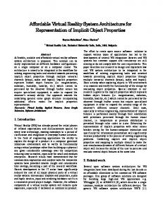
The prototype system uses the following operational logic: system initialisation; excavator specifications read in; numerical model setup; interrogation of operator controls; determination of hydraulic flows; generation of excavator behaviour in 3 dimensions The information regarding excavator behaviour is then transferred to the graphics system The operational logic of the system is shown in Figure 1. In its present state the simulator has data files for several commercial excavators The capacity to quickly configure the excavator being modelled has many advantages in the training environment. The simulator can be easily modified to model other boom based equipment including for example, back hoe loaders and robotic manipulators. 3.3. The graphics system The graphics system uses the information generated by the computational model to produce an "operator's eye view" from the cabin of the excavator. The graphic image is 3D perspectively accurate and updated in real time. The graphics software was created using the C language and the specialised graphics primitives of the Silicon Graphics GL library. The graphics hardware, consists of the Iris Workstation with Elan graphics plus a 19" colour monitor. The system has capacity to draw 40,000 polygons per second in 24 bit colour. This results in an adequately realistic solid 3D image which can be drawn at the required rate of 35Hz for flicker free display. Stereoscopic vision by means of high-speed sequenced left and right eye images and synchronised optical shutter glasses can be provided to improve the immersion of the user in the task. When using presently available technology, a trade-off needs to be made between the level of scene detail, the speed with which the computer can generate 3D images and the cost of the computer. The project team opted for less scene detail with very little surface texturing to ensure that the real time aspects of the simulation were preserved on a computer which was priced within the project budget. Some Gouraud (smooth) shading was used to enhance the three dimensional model by modelling the ambient light conditions. In cases where real time dynamic simulation is not as important an enhanced level of scene detail is possible.
3.4. System interfaces There are three specialised interfaces that enable the integration of the operator controls, the computational model and the graphics system to form the composite simulator. The first interface is between the operator controls and the computational model. The operator controls are electronic and link to a 16 channel analogue to digital card which converts the analogue information from the controls into a digital signal. The digital information is then used by the computational model to generate the hydraulic flow rates. The second interface which occurs between the 486 PC and the graphics workstation was specially engineered by the project team. This interface provides the computational model output to the graphics computer in real time. The performance of this interface is vitally important in the production of a convincing simulation. A third interface that allows the generation of realistic operational sound has also been developed. This interface is based on a sound card which has been installed in the 486 computer. Information relating to engine load is passed from the computational model to a sound card which allows a signal to be generated. This signal is amplified by speakers
243
INTERFACE TO THE REAL WORLD
A TO D CONVERTER
DIGITAL INPUT TRANSFER SYSTEM EXTERNAL DATA CREATOR AND INTERFACE ACTIONS SYNTHESISER
COMMUNICATION LINK - IN
PRINCIPLE.
INTERFACE SYSTEMS MODELLER AND SIGNAL PRE-PROCESSOR
{TEAL TIME CLOCK
MODEL VARIABLE -PARAMETER DATA FILE
ABSTRACT FORM DYNAMIC SYSTEMS MODELLER
y
SYSTEM DESCRIPTION/ STATE MEMORY STORE
SYSTEM STATE AND STATUS REPORTING SYSTEM
COMMUNICATION LINK SERIAL PORT OR ETHERNET BASED
COMMUNICATION SYSTEMS MANAGER
COMMUNICATION SYSTEM S MANAGER
SYSTEM ENTITY AND COMPONENT DESCRIPTION FILES
IMAGE CREATION ENGINE GRAPHICAL; IMAGE CREATION PRIMITIVES
COMMUNICATION LINK
VISUAL DISPLAY UNIT OR UNITS
Figure 1. System architecture and information flows
244
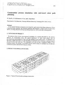
attached to the sound card to simulate the sound an operator would hear when driving the excavator. 3.5. System configuration The operator controls, the computational model and the graphics system are integrated together using the system interfaces to font. the functional excavator simulator. The system arrangement is shown in Figure 2 and Figure 3. 4. THE PROTOTYPE SYSTEM IN OPERATION The prototype system was put into service as a plant operator training tool, by the Tasmanian Building and Construction Industry Training Board in July, 1993. The system is used for the Initial 16 hours of operator training with a graded set of exercises designed to familiarise the trainee with excavator behaviour. The first set of tasks concentrate on familiarisation with the controls and co-ordination to enable simultaneous use of controls. The second set of tasks involve object movement which refine the operators skills for digging and loading. other tasks include trimming a batter, loading a truck and driving the excavator from position to position.
4.1. Comments on the prototype system The prototype system has received virtually complete acceptance from both novice and experienced plant operators. This acceptance demonstrates that low cost advanced three dimensional graphics technology can be developed for effective use in the construction industry. It is interesting to note that the level of immersion technology utilised in the simulator is relatively crude, in that stereo eye wear has not been installed on the prototype. This does not appear to have detracted from the acceptance of the simulator by trainees. Initial results using the simulator indicate that skills learnt during this type of training are immediately transferable to the real excavator. Further work on the transferability of skills and the efficacy of simulator training for plant operators is at present being undertaken by the project team. The successful development of the prototype system has wider implications for the construction industry. Simulation tools, utilising the advanced graphics system and computational techniques used in this project, are now being developed to help solve some of the difficult problems that arise in construction system design and planning as well as other areas of Construction [6]. 5. A SIMULATOR SYSTEM FOR CONSTRUCTION SYSTEM DESIGN AND AUTOMATION PLANNING Based on the platform of the construction plant simulator the project team has begun work on a more generalised construction simulator (The OWP system). The OWP system includes a series of advanced visualisation features that will assist construction automation planners and construction engineering systems designers . These features will be described and potential applications of the OWP system are discussed.
245
5.1. Existing features of the generalised construction simulator The present features of the OWP system include: A movable observer viewpoint The system is able to provide its 3D visual representation from the point of view of a static or moving observer. Any desired observer position can be specified by the user including having the observer moving along a present path during the simulation. The observer position can also be under direct control of the user through a joystick control system.
The effect of this type of observer control is that the simulator user has great flexibility in relating to the dynamic model of the construction activity. For example: a) The observer can be attached to a piece of equipment and move about the construction site. b) The observer can be placed in any number of positions to view the site from overhead, from below etc. c) The observer can move through the site on a preplanned path of under user control giving full walk-through capabilities already available in several software packages [see eg. 1,7]. User configured lensing The system allows the user to place different lenses between the observers eye and the subject. It is possible to have wide angle, telescopic and skew-view lenses. The zoom in and out and width of field of view can be configured by the user. Variable time base Using the software control provided in the system the results of the 3D simulations can be viewed in real time, slow motion, fast time or time-lapse view. Variable control characteristics For any given set of levers or controls the system allows for software setting of particular control characteristics. 5.2. Features under development Work on the OWP system is continuing and new features being developed include: Multi-entry interactive control Facilities for the independent control of more than one object in the system are being added. For example if the simulated situation needs a number of vehicles each vehicle can be individually moved around the site. Therefore the system has the potential to model the interactive behaviour of construction systems. Improved object interaction Algorithms are being developed to improve the fidelity of object interaction. These algorithms improve the modelling of physics of collisions between objects in the simulated environment. It is important to note that the calculations necessary for object interaction must be performed quickly enough to ensure that image generation speed is not reduced. Difficulties in extending the fidelity of terrain interaction are discussed in the military simulator literature [2]. Inclusion of a database facility Development is proceeding on the interfacing of a database with the general simulator Different database systems are being investigated for suitability. It is envisaged that the database will allow the system to access information necessary to portray construction site
246
environs in sufficient detail to be able to carry out virtual construction Equipment simulators Work is continuing to improve the range of construction equipment that can be simulated . This requires the creation of numerical models of different items of equipment including graders, dozers , trucks and tower cranes. Intelligent Systems Modeller
With suitable modification the generalised simulator can be used as a tool in the development of intelligent construction systems . The simulator will be used for testing the performance of information collection systems , operational strategies for the intelligent systems controller and physical systems in the artificial environment 5.3. Applications The authors are confident that the generalised construction simulator has the potential for wide application in the construction industry [6]. Two of the most important areas of application are in construction systems design and automation planning. Construction systems design The real-time 3D graphics of the simulator when combined with a database system will enable construction systems designers to model construction processes. Designers will be able to perform simulated operations in real-time to compare the relative merits of different methods and to improve integration of operations.
It is envisaged that the system will be able to provide a fully simulated construction site environment where 'virtual construction' can be performed by the user. Construction system designers will then be able to step through the construction project solving problems like construct ability, integration of equipment, and interfacing of contractors. Automation planning The 3D simulation of a construction site has a logical extension in the simulation of an automated construction process. The 3D representation of the site can be used to test automated construction systems. The use of different observer viewpoints could provide automation planners with detailed information on object interaction, hazards and difficulties that occur on real sites. There is also the possibility of using the simulated 3D construction site as a map that the construction robot uses to navigate around the real construction site. The map could then be updated to give as constructed information. The additional features required in such a system include the ability to collect, store and retrieve information from the real site to enable the provision of correct information to the construction robot. The three dimensional virtual construction site forms the basis for this system for automated construction.
CONCLUSIONS The development of an advanced graphics based construction simulation system has been described. The development and operation of a prototype system used to train construction plant operators was used to demonstrate the use of simulation technology to produce a virtual' construction system. Further development of the prototype system, which is presently being undertaken, were outlined. The general construction system simulator arising from this development was then placed in the context of a design and analysis tool for construction systems designers and
i
247
automation planners. It is concluded that VR type systems, as described here, will prove extremely useful in the future of the construction industry. REFERENCES 1. Hendrickson, C. and Rehak, D.R., The potential of a virtual construction site for automation planning and analysis, Automation and Robotics in Construction X, G.H. Watson, R.L. Tucker and J.K. Walters (eta.), Elsevier, Amsterdam, 1993. 2. Moshell, J.M. et al., Nap-of-earth flight and the realtime simulation of dynamic terrain SPIE Vol 1289, Cockpit Displays and Visual Simulation, 1990. 3. International Federation of Robotics, Robotics Newsletter, No 7, March, 1993. 4. O'Brien, J. B., Training machines and simulators, Lecture to the Queensland Department of Employment and Labour Relations, 17th January, 1983. 5. Caduri, A. and Kourie, D. G., Cost effective visual simulation based on graphics workstations, South African Computer Journal, 5, 58-69, 1991. 6. Wakefield, R.R. and O'Brien, J.B., Realtime visual output simulation - a new tool process tool for construction planners and managers, Proceedings of the National Construction and Management Conference, Sydney, Australia, February 18-19, 1994. 7. Fisher, D. J. and O'Connor, J.T., Piping erection construct ability issues in a semiautomated environment, 6th International Syposium on Automation and Robotics in Construction, June 6-8 , 1989 . PHYSICAL FEEDBACK ---W PATH --------1
MANUAL CONTROL INTER -FACE
ANALOGUE TO DIGITAL CONVERTER SYSTEM
4b_ I
MODELLING "ENGINE"
VISUALISATION SYSTEM
ARIABLE VARIABLE HOLISTIC MODEL MODELS PARAMETER AND SPEED SETTINGS
VARIABLE EYE PARAMETER AND POSITION SETTINGS
Figure 2- Functional model of the complete simulator -----I 19" Graphics monitor
Speaker
Sound card Silicon Graphics Iris Indigo Workstation
z
A-D card Operator controls Figure 3 - General layout of the simulator
486PC