1Xilinx Research Labs, Longmont, CO 80503 USA. 2Ecole Polytechnique Fédérale de Lausanne (EPFL), CH-1015 Lausanne, Switzerland. 3IMEC, Kapeldreef ...
A VIRTUAL SOCKET FRAMEWORK FOR RAPID EMULATION OF VIDEO AND MULTIMEDIA DESIGNS Paul Schumacher1, Marco Mattavelli2, Adrian Chirila-Rus3, and Robert Turney1 1
2
Xilinx Research Labs, Longmont, CO 80503 USA Ecole Polytechnique Fédérale de Lausanne (EPFL), CH-1015 Lausanne, Switzerland 3 IMEC, Kapeldreef 75, 3001 Leuven, Belgium ABSTRACT
Traditional design and test of complex multimedia systems involves a large number of test vectors and is a difficult and time-consuming task. The simulation times are prohibitively long on current desktop computers. Driving actual design scenarios and timing burst behavior which produce real-time effects is difficult to do with current simulation environments. This paper describes a rapid emulation framework for accessing multiple hardware IP blocks on an FPGA. This solution involves an abstraction of the FPGA platform by having a virtual socket layer that resides between the design and the test vehicles. A rapid prototyping platform is thus created, and its use with complex video and multimedia systems is described. 1. INTRODUCTION Video compression standards in the never-ending search for higher and higher compression performances have reached an extremely high level of complexity. While at the very beginning of the MPEG activities the “text document” was the traditional form for the reference specification of the standard, already with MPEG-2 we have seen the appearance of non-official, but publicly available software versions. It is with MPEG-4 standardization efforts that the software description of the algorithm has become the standard description and the textual part [1] is just provided for clarity and documentation purposes. Any possible ambiguous interpretation is solved by referring to the software description. Therefore, the generic and non-optimized software description has also become the starting point for any implementation activity of the standard. Unfortunately, working and reasoning on architectural solutions or on appropriate software/hardware (SW/HW) partitioning on several tens of thousands of lines is a very time- and resource-consuming task [2]. In the traditional way of designing HW blocks, the full rewriting of the reference software to isolate candidate HW blocks and
0-7803-9332-5/05/$20.00 ©2005 IEEE
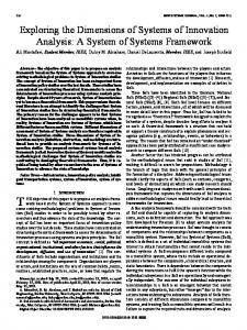
architectures and to generate appropriate test vectors for the correct elicitation of the designed HW system are mandatory tasks that could result in even more resourcedemanding tasks than the HW design itself. Realizing the fact that the starting point of the implementation process is too far removed from a complete implementation, two initiatives have been taken within the MPEG committee. The first is to develop a generically optimized reference software version of the standard (MPEG-4 Part 7 [3]). The second is to derive from such versions mixed SW/HW descriptions for which some parts of the reference software are described by alternative blocks described in an HDL form (MPEG-4 Part 9 [4]). Supporting such mixed SW/HW standard description with appropriate test and emulation platforms is critical to their deployment and acceptance in the industry. The ideal architecture for such platforms includes an easily programmable board that can be plugged into a standard SW environment. Therefore, the tool needed to realize such a platform is a virtual socket that enables a truly integrated, platform-independent environment for SW and HW developments. This paper describes such a virtual socket platform to enable rapid emulation of video and multimedia designs and verify various IP targeted for such systems. In Section 2, the concept of the virtual socket platform is described. Section 3 explains our implementation using an FPGAbased platform. Section 4 then gives results for an entire MPEG-4 decoder instantiated in the platform. 2. VIRTUAL SOCKET PLATFORM A virtual socket platform has been created to aid in the rapid emulation, test, and verification of FPGA designs for complex multimedia standards [5]. This system was targeted specifically to support high-throughput and high data rates usually required by video and multimedia, however, all types of designs could benefit from such an integrated platform. Figure 1 shows the block diagram of the FPGA-based virtual socket platform including N slots
Figure 1: FPGA-Based Virtual Socket Platform for hardware accelerators. Any number of these slots can be utilized for a given build of the platform. A single interface is provided to access the multiple accelerators. All required data and controls for the processing in the hardware accelerators are sent through the interface block. To allow for both controllability and observability of the accelerators by the test/emulation engine, the platform allocates four different memory spaces to each hardware slot in a manner extending the work of [6]: 1. 2. 3. 4.
Table 1: Virtual Socket Memory Allocation Scheme
Write-only register file (written to by test/emulation engine) Read-only register file (read by engine) Write-only block memory Read-only block memory
The register file memories are for the writing and reading of control signals. The write-only register file can be used for important flags and parameters that are necessary for the processing performed by the hardware slot. The test/emulation engine controls how often these values are updated (e.g., video frame type updated every frame). The read-only register file is included for observation of critical run-time controls and can be used to either convey important computed parameters back to the test/emulation engine or for various diagnostic purposes. The block memories are included for the passage of data to/from the test/emulation engine. An example of this would be a discrete cosine transform (DCT) hardware element included in a hardware slot. The input data would be an 8x8 block of 8-bit pixel values, while the output would be an 8x8 block of 12-bit DCT coefficients. Disregarding pipelining, the minimum size of the block memories for this element would be 64x8-bits and 64x12bits, respectively. Table 1 shows a memory addressing allocation scheme assuming N hardware slots and M address locations per memory space for each slot. If N and M are pre-determined values in a system, then an API
Figure 2: Block Diagram of Virtual Socket Platform can be provided to aid in the calculation of memory addresses, abstracting the process away from the software engineer. Figure 2 shows the block diagram of a typical hardware accelerator slot. Note that while the start/end flags and information registers are accessible through the register file memory space, the input/output data uses the block memory space. Figure 2 shows just one example of starting/stopping an accelerator controlled by flags exchanged with the test/emulation engine. Either a push or pull model can be created, where the finish flag can either be polled by the test/emulation engine or can be used as an interrupt signal to the processor. Another method would be a streaming-data model triggered by the availability of the input data as well as the availability of unused locations in the output memory. This type of model would most likely configure the input/output RAMs as FIFOs, allowing for the capture of multiple output values before a read procedure by the test/emulation engine is required. This expands on the capabilities in [7]
Figure 3: Example Hardware Identification Value where only a single I/O set is captured and shifted out using JTAG. Both the push and pull methods of data capture are supported in the proposed virtual socket platform. In order to support access to multiple hardware accelerators on the platform shown in Figure 1, a hardware identification (ID) value is included accessible via a readonly register file location in the master socket. An example of the hardware ID value is shown in Figure 3, where an N+1 bit word is used to specify the active hardware slots in the current build. The test/emulation engine would read this value and determine that two slots are included at locations 1 and 6. There are then two methods for the test/emulation engine to determine the functionality available in this build: 1) use a predetermined table of slot numbers and their corresponding hardware functionality (e.g., a DCT engine is always in slot 6); or 2) use a read-only information register to inform the test/emulation engine the exact functionality that the hardware designer included in a given slot. The actual usage of the hardware slots by the software running on the test/emulation engine can be decided at either compiletime or at run-time as described in [8]. 3. IMPLEMENTATION Figure 4 shows the block diagram of the environment used to verify the concepts of the virtual socket platform described in Section 2. For this exemplary system, the WildCard-IITM PC card is the target platform, providing an excellent co-processing platform in a small, portable CardBusTM form factor [9]. This card is used in conjunction with a laptop where the microprocessor on the laptop becomes the heart of the test/emulation engine for the system. The WildCard-II contains many of the elements necessary for our desired co-processing platform, including the following features: 1. 2. 3. 4. 5.
Xilinx Virtex-IITM XC2V3000 FPGA for processing [10] 64 MB of DDR SDRAM 2 MB of ZBT SRAM 32-Bit / 33 MHz PCI interface Multi-channel DMA controller
Figure 4: Virtual Socket Platform Test Environment A virtual socket interface and hardware API was created for this card providing an HDL/EDIF wrapper for any design. The targeted language supported is VHDL, however, any synthesizable HDL could be used. This interface performs the multiplexing/demultiplexing for accessing the multiple hardware accelerators and also provides access to the two on-board memory chips. For our system, the number of hardware slots, N = 31, providing simple access to the 32-bit hardware ID over the PCI bus. A memory controller is included in the virtual socket interface to arbitrate access to the memories amongst the hardware accelerators as well as provide a simpler, non-physical interface. The test/emulation engine also has access to the memories on the WildCard-II. For faster access to/from the virtual socket platform, the interface also supports DMA transfers. Software code is written for the laptop to perform any functionality not off-loaded to the WildCard-II, including: reading and writing of files; transferring data to/from the WildCard-II; and performing real-time analysis of the results. Examples of such back-end analysis include: comparison of results versus expected values; monitoring sequences of run-time parameters for verification of correct operation; and real-time playing or displaying of results. Since the test/emulation engine has access to both register file and block memory spaces for all hardware accelerators, debug and verification can be performed on not just IP outputs but any desired internal signals and debug counters. This allows very good observability for the operation of an IP. A software API layer written in ANSI C is provided for platform-independent functions to communicate with the platform on the WildCard-II [5]. Functions such as VSWrite() and VSRead() are provided, with the user needing to know the hardware slot number and the starting address value in the shared memory space. Following the scheme shown in Table 1, our system uses a fixed locations per memory space value of M = 512, so the API
also provides macros to simplify the address calculation. Note that the API is layered such that the software designer can write his code in a manner regardless of the actual hardware platform used. 4. RESULTS The virtual socket platform implemented on the WildCard-II was used to verify the FPGA design of an MPEG-4 Simple Profile video decoder. As described in [2], this debug step was used after the VHDL design was verified in the ModelSim simulator [11]. It proved to be an invaluable debug step, not just for verifying actual FPGA hardware, but providing a “bursty” data transfer environment to strain the communication primitives in the design. In order to verify the operation of this complicated decoder design, software code was written for the test/emulation engine to: read the encoded bitstream file(s) located on the laptop; write the bitstream to the WildCardII; read the results from the WildCard-II; and render the output. Since a video design was targeted, the back-end analysis involved displaying the reconstructed video in a DirectX window for both debug and demonstration purposes. On an as-needed basis, the platform also provided access to a number of internal signals and counters for debug purposes. Table 2 shows the emulation performance results comparing three different test sequences: City QCIF @ 15 fps; City CIF @ 30 fps; and City 4CIF @ 30 fps. These tests were performed using Rev. B of the WildCard-II connected to a 1.7 GHz Dell D600 laptop with 1.0 GB of RAM. The overhead times for hardware include operations done in software such as getting the data ready for DMA transfer, polling the output flags, etc. While the typical DMA read data rate was found to be 35-40 Mbytes/sec, it has been shown to be faster on other laptops [12], providing an even faster emulation environment. The clock rate for the FPGA circuit was 49 MHz, giving a much faster emulation time than previously reported in [6] and [7], where verification was performed at a maximum rate of 1.1 MHz. 5. CONCLUSION A virtual socket platform was described here, providing a rapid test and emulation environment for complicated video and multimedia designs. A novel virtual socket concept was described as well as an implementation of that platform using an FPGA-based PC card. Results for emulating an MPEG-4 Simple Profile decoder design using the platform were described. The platform provided a real data transfer environment to verify the actual FPGA
Run-Time Parameters Bitrate (kbps)
Test Sequences City City City QCIF CIF 4CIF 200 1000 8000
Total Frames
150
300
300
Frame Rate (fps)*
223.9
62.9
14.7
DMA Read
0.10
1.18
4.68
Write
0.03
0.34
1.78
Overhead
0.11
0.42
2.26
Total
0.24
1.94
8.72
Re-order
0.10
0.91
3.38
Display
0.33
1.92
8.32
Total
0.43
2.83
11.70
0.67 4.77 Total Time (sec) * Frame rate found using “free running” mode.
20.42
Hardware (sec)
Software (sec)
Table 2: Emulation Performance Comparison hardware design. A demonstration of the decoder running on the WildCard-II can be shown. 6. REFERENCES [1] Information Technology – Generic Coding of Audio-Visual
Objects – Part 2: Visual, ISO/IEC 144962-2:2004, June 2004. [2] K. Denolf, et al, “A Systematic Design of an MPEG-4 Video Encoder and Decoder for FPGAs”, GSPx 2004, Santa Clara, CA, USA, September 2004. [3] Information Technology – Generic Coding of Audio-Visual Objects – Part 7: Optimized Reference Software, ISO/IEC TR 14496-7:2004, October 2004. [4] Information Technology – Generic Coding of Audio-Visual Objects – Part 9: Reference Hardware Description, ISO/IEC TR 14496-9:2004, June 2004. [5] P. Schumacher and R. Turney, “Integrated Framework for MPEG-4 Part 7, Part 9, Part 10,” ISO/IEC JTC1/SC29/WG11 N6092, Hawaii, USA, 8-12 December 2003. [6] Y. Nakamura, et al, “A Fast Hardware/Software CoVerification Method for System-On-a-Chip by Using a C/C++ Simulator and FPGA Emulator with Shared Register Communication”, DAC 2004, San Diego, CA, USA, June 2004. [7] R. Siripokarpirom and F. Mayer-Lindenberg, “HardwareAssisted Simulation and Evaluation of IP Cores Using FPGAbased Rapid Prototyping Boards”, International Workshop on Rapid System Prototyping, Geneva, Switzerland, June 2004. [8] T. Mohamed, et al, “A Rapid Prototyping Framework for MPEG/H.264-enabled Consumer Products”, ICCE 2005, Las Vegas, Nevada, USA, January 2005. [9] Annapolis Micro Systems, http://www.annapmicro.com. [10] Xilinx, Inc., http://www.xilinx.com. [11] Mentor Graphics / ModelSim, http://www.model.com. [12] Annapolis Micro Systems, WildCard-II Reference Manual, Rev. 2.6, 2004.