the details of low{level issues such as process schedule ... simulation stage is the scheduling and dispatching ..... Software, pages 80{83, August 15-19, 1988.
A Visual Environment for Designing and Simulating Execution of Processor Arraysy Charles D. Norton and Ephraim P. Glinert Computer Science Department Rensselaer Polytechnic Institute Troy, NY 12180
Abstract
Novis, a visual environment which supports the inter-
active development and animated simulation of special purpose parallel architectures, is presented. In sharp contrast with other systems which concentrate on the representation of parallelism within programs, Novis lets users design networks at an abstract level by placing processing elements into a connected grid of arbitrary (user selected) shape. The environment's underlying philosophy of maximal information hiding makes intimate familiarity on the part of the user with the details of low{level issues such as process schedule maintenance and event dispatching unnecessary. Layout violations and exceptions detected during execution simulation (e.g., deadlock) are automatically reported to the user. An overview of Novis's features is followed by examples that show o� the environment's capabilities in a variety of useful applications.
Introduction
The most commonly used techniques for designing parallel array processors and for developing parallel algorithms employ graph{based methodologies which are visual in nature. The motivation is clear: in the parallel architecture domain, graphical depictions often convey information (e.g., regarding processor connectivity, computational dependencies and physical resources) more readily than either recursive expressions or pseudo{code. Visualization of concurrency in programming languages and systems, although still an open reThis research was supported, in part, by the National Science Foundation under contract CDA{8805910. y
search area, has received some attention in the literature from a variety of perspectives [1, 2, 3]. Our approach in the Novis environment is to support interactive, visual design of complex parallel networks of communicating processes. Computations are speci ed as data ow graphs (DFGs) whose nodes represent processing elements (PEs) which execute instructions in some sequential programming language. The DFG's edges dictate the connectivity among the PEs, and represent the communication paths. Dependencies are speci ed by these edges, while synchronization is enforced by the execution schedule. Once the design has been completed, an animated execution simulation can be viewed on demand. Thus, Novis encompasses the properties commonly associated with both visual programming environments [4] and parallel programming environments. Indeed, it may be thought of as a rst step towards a visual parallel programming environment .
System Overview
Novis runs under UNIX� and MIT's X Win-
dow System on Sun Microsystems SPARCstations and Digital Equipment Corporation DECstation/3100s. In the current implementation, UNIX's multiprocessing facilities are used to simulate on a uniprocessor the e�ect of parallel execution. However, Novis's interprocess communication server executes independently, and could easily be modi ed to allocate process requests to multiple processors if suitable hardware were �
UNIX
is a trademark of AT&T Bell Laboratories.
available. The user interface (UI) utilizes color and icons as signi cant means of communicating information. Therefore, although it is possible to use the system with a monochrome display, this is discouraged. Novis permits simulation of various standard architectures such as SISD, SIMD, MISD and MIMD. Communication among PEs is performed via message passing, where processes send and receive messages containing a variety of information. The message passing system is implemented using a client/server model where communicating processes make server requests and receive acknowledged replies. A exible set of routing primitives is provided. In the current implementation, however, this set is not user{extensible. Although for the most general designs this could be considered a limitation, for a wide range of array processing applications the required set of primitives is well known [5]. The primary operation that occurs during the simulation stage is the scheduling and dispatching of PE events . In this paper, a PE event refers to the execution of the C code fragment represented by the PE, subject to the satis ability of its input speci cation. To schedule an event is to arrange for a PE event to occur along a hyperplane which represents some subset of PEs that will execute in parallel. Events are dispatched when their scheduled hyperplane arrives. We will also refer to input events , which represent the availability of data on the input queues of a PE. When a PE's input events are satis able, the PE event is satis able. We will return to this point later on. The internal system resources for maintaining the parallel simulation environment include the process scheduling and event dispatch system , the process server and the public clients which provide message passing (communication) services to the server. An intimate familiarity on the part of the user with the details of how these issues are handled is unnecessary, since they are largely hidden through the UI. Some knowledge of the features provided is nonetheless desirable. We will point out relevant information when the execution details are discussed. The fundamental UI components consist of the development window , the processor library , the processing element dock , the warning system and
the system utilities . While many of these always remain visible, some only appear (automatically) under exceptional conditions, or at the user's request.
Development Window:
PEs are instantiated into the development window during the design stage. The simulation occurs here as well, and system warning messages and user{requested system utilities also appear here. Execution properties of PEs are location independent. A processor placement grid, normally invisible, may be displayed at the user's request. Scroll bars, located at the top and left edges of the window, are provided for adjusting the eld of view.
Processor Library: This window contains a menu
of all available PEs, both built{in and user{de ned. These are grouped according to common properties, and a scroll bar allows referencing of particular groups. Each processor element is represented by an icon which serves as a visual abbreviation for a sequence of instructions and routing primitives. These icons contain arrows that indicate connectivity and an image that illustrates function. Color is used to denote intrinsic properties of PEs (e.g., state information for input queues).
Processing Element Dock:
This window's purpose is to provide easy access to a subset of PEs selected by the user from the processor library for possible placement in the development window as part of a system design. The PE last selected (whether from the library or the dock) is designated as currently active. PE selection from the dock is accomplished by using the mouse to move the cursor over the appropriate icon; no click (button press) is required. The dock is a dynamic window whose size changes as PEs are added and deleted from it. In the present implementation, it can hold a maximum of ten processors.
Warning System: This important feature informs
the designer of layout and simulation exceptions. For example, due to the exibility allowed in the design stage the potential exists for an inexperienced designer to construct a system that will deadlock. The warning system will detect such violations and graphically report them during the execution of the design. A warning preempts all other activity, and development cannot be resumed until the notice has been acknowledged and the problem corrected.
2
System Utilities:
these are detected and reported by the warning system during the design or execution simulation stage, as appropriate.
These simplify the design and simulation environments. Common utilities include options to select various data les for PE queue loading, for graphical speci cation of wavefront propagation vectors, and for general operations to modify the currently displayed design.
The Simulation Phase
Novis's graphical representation naturally and
The Design Phase
immediately makes clear whether certain attributes essential to an e�ective parallel system are preserved or not. For example, the DFG representation must not contain any isolated nodes. The reason for this restriction is clear: every node (PE) in the DFG must have its input events satis ed before it can execute, and an isolated node will never have satis able input events, so it will never execute. Directed edges in the DFG mindicate the transfer of messages. The edge � ?! indicates that node requires a message m from node �, and that will not execute until m arrives. The aforementioned property is a fundamental restriction of many multiprocessor environments. In fact, this restriction may cause deadlock! Since a processor may be placed in a manner such that its input events can never be satis ed, the processor will never execute, and the wavefront on which the processor resides will be halted. Novis's process server will detect such errors, however, and send a message to the resource library client, at which point the simulation will be aborted. The policy of unsatis able PE events is dependent on the implementation of the processing element. This is because the execution properties of a PE are independent of the server. The server can detect information regarding the status of the PE computation, but only report this information to the PE implementation module. The default action for system de ned PEs is that all of the PE events must be satis able for a deadlock signal to be prevented. Separation of the mechanism for detecting a di�culty from the policy that resolves it has great advantages, not the least of which is that the user can choose to implement another policy without any modi cation to the server. For instance, any PE event which cannot be satis ed might be assigned some default value; this deadlock avoidance technique is common in many array processor designs.
We begin the design of a parallel system using Novis by selecting PEs of interest from the processor library and transferring them to the processing element dock. The contents of the PE dock may be adjusted on the y as a design evolves. Which PE is currently active is indicated visually to the user. The processor library can now be removed from the display, and the user begins to compose the required design in the development window. As many copies of the active processor as desired may be placed into the grid by simply clicking repeatedly with the mouse over the desired locations. Connectivity of the design is determined by processor selection. After a design has been con gured, various system characteristics including wavefront propagation direction and the contents of the input queues must be speci ed. Input is loaded as unstructured streams of data from user de ned les. System utilities acquire le names automatically through graphical selection. The queue(s) to be loaded with the chosen data is/are similarly determined by pointing with the mouse. No key strokes are necessary. At this point, the design can be simulated and the results can be examined. If the user doesn't like what he/she sees, the design can be modi ed and subsequently re{executed by simply adding or removing processing elements. There is no need to \compile" a design before it can be executed; indeed, this notion has no meaning in an interactive environment like Novis. Naturally, many of the same di�culties that can occur during program development using standard languages can arise when working in Novis as well. Examples include unde ned input and speci cation of operations that can never occur. As previously mentioned, errors such as 3
client/server routing primitives whose arguments de ne the routing direction in a local or global manner as well as the type of message transmitted. Because processor function is implemented by writing a C program, the user has complete
exibility in terms of what privately de ned processors compute. All processors have the capability to send and receive both local and global messages. Mechanisms needed to perform routing requests (e.g., port declarations) are provided and managed automatically, and need not be explicitly spelled out by the designer, who is only concerned with the speci cation of processor functions and routing. PE interface rules are readily observed from the graphical representation. The types of information that may be transmitted include integer,
oating point or character data. The status returned is used to indicate the success or failure of the transmission. Failure during a transmission can range from specifying an improper processor address to sending invalid data types. Under most circumstances, however, the processor address never needs to be speci ed explicitly. This is because the server maintains statistics on executing processes and automatically computes the location of the next processor based on the routing direction. Since global routing primitives are provided, the PE designer is responsible for specifying the correct address of the destination processor under these circumstances. Once a message which arrives on the input queue of a PE is acquired, it is consumed and cannot be recovered, in accordance with the convention that messages are consumable resources in a distributed system. This aids in the development of such systems, since state information is not retained. Thus, the connection of heterogeneous PEs is only dependent on the satis ability of input events. There is no dependence on the content of the message transmitted, unless the PE designer creates a PE where this property is desired.
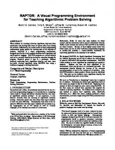
Figure 1: Model of Array Processing. As previously mentioned, the order of execution of PEs depends on the wavefront propagation direction selected, and the e�ects of execution depend on the types of PEs chosen. The schedule de nes the execution order for all PEs in the design. This control thread is contingent upon the availability of the requisite input data. As long as input is available, the system will execute. Thus, a series of wavefronts will be observed at execution time, and the availability of data at the input queues of the design, along with the schedule, create a wave generator. These waves propagate through the design in a direction normal to that of the schedule, until they terminate at the boundary of the design. When all propagating waves have terminated, the simulation ends, and the results (in the output queues) can be examined. We note that the concept of wavefronts as a mathematical de nition of synchronous communication of parallel processes is well documented in the literature [5]. Fig. 1 illustrates these concepts.
Processing Element Details
Novis comes with many built{in processor element types, including I/O queues, addition, multiply, comparison and weighted sum operations, to mention but a few. The designer can also create private PEs using a set of six built{in
Example Applications
We now brie y describe three special{purpose parallel systems and their implementation using Novis (cf. Fig. 2). In all cases, to derive the 4
Figure 2: Novis Simulation of Sorting (top), Matrix{Vector Multiplication (bottom left) and Convolution (bottom right) on a Parallel Array Processor. 5
required DFG we must formulate our algorithm recursively so that it yields a set of space/time relationships among the data and values computed from them. The associated index space determines the location and connectivity of PEs in the DFG lattice. The data dependencies in the algorithm are represented by the edges, while the PEs represent the function computed.
Sorting:
in the Figure. This can be seen from the following recursive expression, derived from the original sum: z = z ?1 + x � y ? i;k
end
where i and j represent indices in the lattice space such that i increases toward the east and j increases toward the south. The k[i; i] are preset to ?1, and the original (unsorted) collection of integers x(i) are loaded into x[i; 1]; the nal (sorted) sequence k[j ] is equal to fk(n; j )g1� � represented in decreasing order. n
Matrix{Vector Multiplication: Given an n � n matrix A and an n � 1 vector ~b, we would P like to compute the n � 1 vector ~c such that ~c = =1 A ~b . A recursive formulation for this equation is given by:
References
n j
ij
j
[1] L. Snyder. Parallel Programming and the POKER Programming Environment. IEEE Computer , 17(7):27{ 36, July 1984. [2] P. D. Stotts. The PFG Environment: Parallel Programming with Petri Net Semantics. In Proc. 21st Hawaii Int. Conf. on System Sciences (HICSS{21), Kailua Kona|Volume 2: Software Track , pages 630{ 638, January 5-8, 1988. [3] S. Sobek, M. Azam and J. C. Browne. Architecture and Language Independent Parallel Programming: A Feasibility Demonstration. In Proc. 1988 Int. Conf. on Parallel Processing, University Park, PA|Volume 2: Software , pages 80{83, August 15-19, 1988. [4] E. P. Glinert, M. E. Kopache, and D. W. McIntyre. Exploring the General{Purpose Visual Alternative. J. Visual Languages and Computing , 1:3{39, March 1990. [5] S. Y. Kung. VLSI Array Processors. Prentice Hall, Englewood Cli�s, NJ, 1988.
c +1 = c + a b where c 1 = 0, a = A and b = b~ . The natural lattice space for this expression places the a into the PEs, while the b are loaded from the west. The c (which represent ~c at index space j ) will emerge from i;j
i;
i;j
i;j
i;j
ij
j
j
j
i;j
j
Convolution: fx(i)g0� � i
i;j
i
the south.
Given two sequences of numbers
?1 and fy(i)g0� � ?1 , we must compute:
n
i
z (i) =
n
X x(k)y(i ? k) i
k
k
parallel programming. The system's goal is to give free rein to the user's creativity while letting him/her work in a natural and convenient manner. Information hiding is employed where{ever possible, as a means to encouraging the design of parallel arrays from an abstract perspective. Since the environment is interactive, the user may modify the DFG representation \on the y" and resimulate the design immediately. The keyboard is rarely used (in fact, its sole function is to save and recall design le names). Most operations can occur in any order, and the e�ects are immediate. SIMD machines have been available for some time. However, Novis encourages the development of heterogeneous systems containing hundreds of PEs. Potential application domains for environments such as Novis therefore include image processing and neural network simulations. Future enhancements may involve increasing the representation to higher dimensional space, and porting the system to a multiprocessor architecture.
n
max [x (i ; j ); k (i ; j )] ?! k (i + 1; j ) min [x (i ; j ); k (i ; j )] ?! k (i ; j + 1)
i
i
Novis represents a new approach to dealing with
for i := 1 to n do for j := 1 to i do begin
j
k
Future Research
Given a sequence of integers fx(i)g1� � and a recursively{formulated sorting algorithm, the required transformation is straightforward; hence the suitability of this problem as a rst example. The algorithm we shall use for the design of our array is the following: i
i;k
=0
where the y(k) are loaded from the south, the x(k) are loaded from the west, and the z (i) ow from the north
6