VERTIPH is a visual programming language that has ... subset of ANSI-C with hardware-oriented syntax extensions such as ..... York, NY, USA, 6th edition, 2001.
Hindawi Publishing Corporation EURASIP Journal on Embedded Systems Volume 2006, Article ID 72962, Pages 1–8 DOI 10.1155/ES/2006/72962
A Visual Environment for Real-Time Image Processing in Hardware (VERTIPH) C. T. Johnston, D. G. Bailey, and P. Lyons Institute of Information Sciences and Technology, Massey University, Private Bag 11222, Palmerston North 4442, New Zealand Received 14 December 2005; Revised 4 May 2006; Accepted 28 May 2006 Real-time video processing is an image-processing application that is ideally suited to implementation on FPGAs. We discuss the strengths and weaknesses of a number of existing languages and hardware compilers that have been developed for specifying image processing algorithms on FPGAs. We propose VERTIPH, a new multiple-view visual language that avoids the weaknesses we identify. A VERTIPH design incorporates three different views, each tailored to a different aspect of the image processing system under development; an overall architectural view, a computational view, and a resource and scheduling view. Copyright © 2006 C. T. Johnston et al. This is an open access article distributed under the Creative Commons Attribution License, which permits unrestricted use, distribution, and reproduction in any medium, provided the original work is properly cited.
1.
INTRODUCTION
FPGAs (field programmable gate arrays) are ideal in many embedded systems applications because they have several desirable attributes: small size, low-power consumption, a large number of I/O ports, and a large number of computational logic blocks. As they have grown in size and functionality, there has been increasing interest in using them as implementation platforms for image processing applications, particularly real-time video processing [1]. Images have a high degree of spatial parallelism, and thus image processing applications are ideally suited to implementation on FPGAs, which contain large arrays of parallel logic and registers and can support pipelined algorithms. However, there is a significant cost in obtaining the increased performance of FPGAs because their architecture differs significantly from the fixed architecture of standard processors. As Offen [2] has stated, the classical serial architecture is so central to modern computing that the architecturealgorithm duality is firmly skewed towards this type of architecture. Consequently, most image processing practitioners are not familiar with parallel programming issues such as concurrency, pipelining, priming, and bandwidth issues. Programming FPGAs differs significantly from writing software for conventional single-processor, large-memory systems in another respect. With FPGA-based designs one designs not only the algorithm, but also the architecture on which it is implemented. FPGA-based designs generally comprise a large number of simple processors which all work in parallel and may compete for memory access or other re-
sources. In designing an appropriate algorithm for the FPGA it is therefore necessary to take into account the limited bandwidth, particularly when accessing memory. The three main processing models used for image processing algorithms on FPGAs—stream, offline, and hybrid processing—have differing characteristics. In stream processing, data is presented as a one-dimensional pixel stream by means of a suitable access pattern [3], typically raster order (in which pixels are presented left to right for each image row beginning with the top row). This converts the spatial distribution to a temporal stream and is often used for processing video data in real time as the data is streamed through the system. This type of processing is well suited to stand-alone configurations—for example, a system in which an FPGA fed directly by a continuous stream of data from a video source is acting as the “front end” of a smart camera, processing the image from a sensor before storing the result into memory. The strict time constraints involved with stream processing depend on the video capture rate and image size (e.g., each of the 25 frames that PAL produces per second contains a 768 by 576 colour image). Stream processing constrains the design into performing all of the required calculations for each pixel at the pixel clock rate. If this is not possible, then some pixels in the stream will be missed and so will not be processed. In some nontrivial applications, such as lens distortion correction [4, 5] or object tracking [6, 7] it is difficult to achieve these high data rates, because each pixel requires complex calculations that may easily exceed a single clock
2
EURASIP Journal on Embedded Systems
cycle. In such situations it is common to break the calculation down into several phases, and to implement the hardware algorithm as a pipeline, with one clock cycle allocated to each stage. At any instant, successive stages of the pipeline will contain pixels at successive stages of processing. The overall rate of output will be one pixel per clock cycle, but there may be a latency of several clock cycles between inputting a raw pixel and outputting the processed result. Pipelining is an important technique for exploiting the temporal parallelism inherent in stream data. In stream processing, memory bandwidth constraints dictate that as much processing as possible is performed on the data as it arrives. For some operations, the order in which pixels are required for processing does not directly correspond to their arrival order from the raster, so the image must be partly or wholly buffered. However, memory is limited on an FPGA, and applications that require full-frame buffering, such as image warping, must typically use offchip memory, which introduces additional latency. In applications where multiple accesses are required such as bilinear interpolation [8], the limited bandwidth and serial access make it difficult to retrieve desired pixel values. Offline processing is commonly used in hosted system configurations. In such a configuration, the FPGA is a coprocessor in the embedded system, whose role is to complement the host computer by accelerating certain tasks. In this mode, there is no longer the strict timing constraint on the processing; random access to shared memory is possible and desired pixel values can be obtained over a number of clock cycles. This allows the bandwidth constraints to be relaxed at the expense of processing time. Hybrid processing combines stream and offline processing. For example, stream processing can be used for image capture and display while offline processing can be used to provide random access to a region of interest in the captured image. VERTIPH is a visual programming language that has been designed to capture algorithms for real-time video processing on FPGAs. This application area has a number of specialised requirements, and VERTIPH provides three views of a design. Each view is tailored to the characteristics of a particular level of abstraction. Before describing these views in detail, we shall characterise some existing languages designed for capturing image processing applications. 2.
PRESENT LANGUAGES
Schematic entry is too low-level as a design tool for image processing as it does not capture the algorithmic nature of image processing functions adequately. HDLs (hardware description languages) were developed to allow designers to capture the high-level temporal behaviour of complex digital designs as well as their circuit structure. Verilog [9] and VHDL [10] are industry standard HDLs. Such languages can be thought of as the assemblers of hardware programming providing great flexibility from gate level up to the behavioural level. As most of them offer similar functionality, we will concentrate on two, VHDL and JHDL. The low-level
constructs supported by VHDL make it a poor choice for implementing complex image processing algorithms. As a general purpose language, VHDL offers no specific support for image processing operations. While HDLs offer a great deal of flexibility in terms of the control logic it is up to the designer to construct any state machines required to control the system. This can be advantageous, thus allowing very efficient control over the execution path. However this burdens the designer with designing both algorithm and the control logic. JHDL [11–13] is a structural HDL developed specifically for custom computing machine design on FPGA devices. This has led to a language which is more intuitive and easy to learn than existing FPGA design tools. JHDL incorporates the ability to design a circuit and simulate this circuit in an integrated package. This includes visualisation tools for the design including: schematics, waveform diagrams, memory views, and hierarchical design viewers. The biggest advantage of JHDL over other low-level HDLs is the integration of the development and debug environments. The power and flexibility of HDLs imposes an exacting low-level programming style that can obscure the broad sweep of a high-level algorithm. There have been a number of approaches to producing high-level design tools that circumvent this problem. One is to modify an existing software programming language to add in the constructs required for building hardware. In most conventional programming languages, statements are executed sequentially following the order of assignment statements, and branches are specified by flow-ofcontrol (while-, if -, etc.) statements. In general, conventional programming languages do not offer the ability to run processes in parallel, although some support process threads. The lengths of data types are defined by either the fixed architecture of the processor (ANSI-C) or by the language (Java). These languages are not designed to be compiled into hardware, so they lack hardware-oriented constructs such as ways to define communication between different processes, to create RAMs, and to assign I/O pins. There are five main areas in which conventional programming languages need to be extended in order to support hardware design. It should be possible (i) to build architectural components such as RAMs, ROMs, WOMs, channels, (ii) to specify that operations occur concurrently and to specify the timing or clock speed of processes, (iii) to define communication between processes running at different speeds, (iv) to create low-level structures such as wires along with bit-level operations such as bit concatenation, (v) to define data types in terms of their bit length. Handel-C compiles algorithms written in a high-level Clike language directly into gate-level netlists. It is based on a subset of ANSI-C with hardware-oriented syntax extensions such as variable data widths, parallel processing, and channel communication between parallel processing blocks. The language is designed to allow software engineers to express an
C. T. Johnston et al.
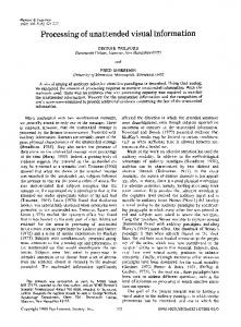
Takes 3 clock cycles
seq a = a + b; b = c; x = y;
3
In normal C flow, the order of instruction flow goes down the page
�
Takes 1 clock cycle
par a = a + b; b = c; x = y;
Develop algorithm C / Matlab Map algorithm to hardware Implement design in HDL
All operations run in parallel so there is no order implied by the layout
�
Figure 1: Logical flow of instructions.
Compile design Place & route on target device Verify implementation on target device
Behavioural and functional simulation Speed/resource optimisation System debug
Figure 2: Image processing on FPGA design flow.
algorithm without requiring any knowledge of the underlying hardware [14]. Apart from the introduction of architectural constructs and bit-level operations, the only significant difference between ANSI-C and Handel-C is the introduction of the par construct. All statements within a par block run in parallel. Handel-C provides a good level of abstraction from hardware design. However, its textual nature makes the data flow in a parallel design difficult to understand. Figure 1 shows that there is almost no visual difference between sequential and parallel codes. This is common to all text-based HDLs. The increased ability to concentrate on algorithm development comes at a cost: loss of control over details such as control flow; Handel-C builds an implied state machine to control the data processors. Another approach is the hardware compiler which takes all the hardware design decisions except data-type lengths away from the designer. This approach has been taken by SAC [15, 16] and MATCH [17]. SA-C incorporates common image processing functions such as array summing for histograms and window loops. It exploits parallelism primarily through loop unrolling and low-level pipelining. These systems take all control away from the designer. They can achieve real-time operation using an offline design model. However they can only optimise an algorithm through pipelining the sequential algorithm. While many image processing algorithms are inherently parallel, they are commonly expressed serially, for implementation on a serial processor. For example a filter is parallel in its specification, but is normally implemented as loops. Most image processing applications involve several steps which can each run concurrently as pipelined processes. It is therefore desirable to have a development tool which allows this parallelism to be captured at an appropriate level of abstraction. 3.
CURRENT APPROACH
When implementing algorithms on an FPGA we have used the design flow shown in Figure 2. Most of the effort in following this path is in the first step: mapping an algorithm into a form suitable for FPGA
implementation, generally using a stream processing model. The aim is to make the implementation as efficient as possible, which we accomplish by coarse-gain pipelining (between operations), fine-grain pipelining (breaking up operations), combining operations into one, utilising look up tables, CORDIC functions, and redesigning a standard algorithm for a single-pass implementation. This high-level design is then implemented onto hardware using a hardware language, such as Handel-C. There is a large semantic gap between our design mapping and the hardware languages used to implement the design. A highlevel language for expressing image processing algorithms in hardware should make this gap easier to bridge. It should (i) allow a mixture of parallel and sequential design; (ii) make it clear to the designer what runs in parallel and what forms part of a pipeline; (iii) be able to detect when concurrent processes may access a shared resource such as a RAM, and manage this accordingly by informing the designer and giving some suggestions as to how to resolve the issue; (iv) be able to handle stream, offline, and hybrid processing models; (v) include some of the common image processing functions and data types as primitives. Examples include row and pixel buffering, window filters, and look up tables (LUT); (vi) be intuitive and easy to use; (vii) provide multiple views onto the design. Currently no system incorporates all of these features, and this paper describes a system which meets these requirements. Visual design tools can aid in the specification and development of image processing algorithms. There have been a number of different visual image processing languages for use on a serial computer including Khoros [18] and OpShop [19]. There are also several general purpose visual languages which can be used for image processing, including LabView [20] and Simulink [21]. Khoros, LabView, and Simulink now have extensions that allow them to be used for FPGA design,
4
EURASIP Journal on Embedded Systems
Camera interface Data flow Control flow
Frame buffer manager RAM1 RAM2
Bilinear interpolation
Video driver
Barrel correction
Keyboard interface
Figure 3: Architecture view of a barrel distortion correction system showing components, control, and data flows.
although this was not their original purpose. Khoros offers a high-level view for algorithm development, but it does not include lower-level design capabilities, as it was not designed to support the implementation of novel image processing operations. Recently other IP-based systems such as Celoxica’s PixelStreams [22] and Xilinx’s DSP block sets [23] have been developed to provide faster development time for projects and provide similar functionality to Khoros. These languages all follow a form of the dataflow paraldigm where streams of data flow through a network of nodes, each of which performs a computation on the tokens within the stream before passing the output data to the next node [24]. It has been noted [25] that dataflow graphs (the natural visual representation of this programming paradigm) are an effective representation for problems in digital signal processing (DSP), both because they are a natural representation for many DSP researchers and because they expose parallelism in the algorithm with limited constraints on evaluation order.
As discussed in Section 3, textual languages represent concurrency and complex scheduling poorly. We have developed VERTIPH, which incorporates a visual representation for representing the parallel design of image processing algorithms. As image processing algorithms often involve a number of largely independent processing blocks, a suitable highlevel view allows the designer to specify the data flow through a sequence of modules. This is then augmented with lowerlevel views that support the definition of parallel computations that make up the higher-level modules. Finally a resource and scheduling view is provided, so that the designer can specify the timing between the operations, and access to resources. These three are the defined views of the VERTIPH system: the top-level architecture view, a computational view, and the scheduling and resource view. A comparison of VERTIPH with other HDLs and its required features was presented in [26]. This work expands on VERTIPH’s features including data types and operators.
as several blocks that operate sequentially on the image data. Khoros and OpShop are other systems that act at a similar level. The use of component blocks allows resources such as frame buffers to be encapsulated, and related computational processes to be logically grouped. For example, a frame buffer component will have both an input stream and an output stream, and it will contain two RAM banks. Other components which communicate with this only see address and data lines and the switching between memory banks can be done within the component. Processors which are logically related to each other are also encapsulated. For example, a colour segmentation and tracking algorithm detailed in [6, 7], represents each uniquely coloured detected object as a bounding box. It stores the bounding boxes for each colour class in a data structure, and it incorporates processors for tracking-related bounding boxes between frames and for calculating the position of all the bounding boxes that have been detected. The data structure and the processors are logically related and should therefore be kept together. This idea of encapsulation borrows from object-orientated software engineering. Encapsulation simplifies the sharing of data and resources and it becomes clear which processor can access them and for what purpose. It can in turn make it easier to schedule these processors, as the developer does not need to remember all the parts of the system which are related to the resource or data structure being used. Hierarchical encapsulation can allow for very complex IP blocks to be built, with one block and interfaces representing a complex system of data structures, resources, processes, and their scheduled operations or response to events. It also allows for a hierarchy of state machines to be used, with each component within a component having its own state machine which may or may not then be controlled by a higher level of the design. The aim of the architectural view is to allow logical separation of image processing operators, to show the data flow through the operators, and to encapsulate data and processors related to each operation.
4.1. Architecture view
Data types
The architecture view (Figure 3) aims to provide the designer with a perspective on the overall system. As image processing algorithms are broken up into blocks which perform very specific processing tasks, they can be developed independently and validated using test image data. This view allows the designer to construct an image processing algorithm
Data types commonly encountered in image processing include 16-, 24-, and 32-bit colour, 8- and 16-bit grey scale, and signed and unsigned integers, and fixed point numbers of arbitrary size. The user therefore needs to be able to specify the type of a data stream; that is, its size and format. And, as communication in FPGAs may be by channel, by register, or
4.
VERTIPH
C. T. Johnston et al. by wire (no storage), it is appropriate to include path-type information in the type specification along with the more traditional size and format information. The data flow between high-level blocks is shown in VERTIPH’s architecture view, so the architecture view editor incorporates type checking to give the user feedback about whether the data being output from one block is acceptable as input to another. This happens as soon as a connection is established between two high-level operators. The data types of the output that drives the connection and the input that it feeds into are immediately compared to ensure that they are of the same type, and the user is informed if they do not match. Floating point numbers have not been included within the system for several reasons: 32- or 64-bit IEEE standard 754 floating point numbers are expensive to implement in terms of memory, circuit size, and power consumption. Image processing operations generally do not require the dynamic range which floating point offers. Fixed point numbers offer better overall noise performance when the probability density function of the signals is uniform [27]. As long as appropriate fixed point word lengths are chosen, almost all standard image processing operations can be implemented (with some degree of rounding error). Fixed point operations have a small footprint in hardware and lead to lowerpower consumption, thus making them the best choice for embedded applications [27]. Figure 4 is the dialogue for specifying the size and range of fixed point numbers in VERTIPH. The dialogue allows the number of bits before and after the binary point to be altered, using either a slider interface or a text box. Another advantage to capturing type information is that this information can be used to automatically align values for arithmetic manipulation, and to generate a register of the correct width to store the result. Figure 5 shows the intermediate registers required to implement a multiphase calculation involving a multiplication, an addition, and a subtraction. It shows that if the order of operations is changed, the registers for the intermediate results must be altered. This is an exacting task, and—if it is performed by the designer—a fruitful source of errors, but the availability of type information in VERTIPH makes it possible to eliminate the errors by calculating the register sizes automatically. Specialised operators Window filters are a very common low-level image processing operator. There are several forms that a window operator can take in hardware [28], and they need to be tailored to the application. Therefore a design wizard for constructing operators of this type has been developed for VERTIPH. As in other fields, certain patterns are found repeatedly in the design of image processing systems. Each application shares some properties with other applications, and each application has some unique parameters. We have therefore designed VERTIPH to allow new patterns to be incorporated into the language as wizards. The window operator is simply the first of these.
5 Data Type Editor Data Type S7.3
Step Size
Range 8.0 : 7.875
0.125
Figure 4: Fixed point data type editor.
S4
�
U5 + U6
S9
+
U4 U6
S10
S4
�
U5 + U6
U4
S9 S10 S10
S U 9
Signed Unsigned 9 bits
Figure 5: Different temporary register sizes depending on arithmetic order.
4.2.
Computational view
Developers who never design their own algorithms can use the architecture view’s editor to assemble predefined library modules into a high-level overview like the one shown in Figure 3. This is similar to the way that other IP-based systems such as Celoxica’s PixelStreams and Xilinx’s DSP block sets operate. However, to allow developers to design their own operations and to help with buffering, pipeline priming, and synchronisation, a lower level timing view is needed. The computational view aims to improve the visualisation of the concurrent aspects of the low-level computations. To accomplish this we have modified the Gantt chart notation [29] which was designed as a visual tool to highlight the temporal relationships and dependencies between phases in large construction projects, and thus make it easy to schedule timecritical activities. In this notation, time flows from left to right, so Figure 6(a) shows a sequential set of operations; operation A is followed by operation B, which is followed by operation C. In Figure 6(b), the operations occur concurrently, and in Figure 6(c) they are pipelined. This representation is an abbreviation of Figure 6(d) which explicitly shows the parallel repeating processes, the passage of data from one to the other, and that each process is active in succeeding phases. Of course, these basic types can be used together as shown in Figure 7, which is the pipeline for row processing used by the barrel distortion algorithm [5]. This figure also shows the if - and while- control structures provided by VERTIPH, which are based on the control structures used in Nassi-Shneiderman diagrams [30]. The top bar displays the
6
EURASIP Journal on Embedded Systems Time A
B
A
C
A
A
A
B
B
B
C
C
C
A B B Concurrency C (a)
C
(b)
(c)
(d)
Figure 6: Process representations: (a) sequential, (b) parallel, (c) pipelined, (d) actual pipeline structure.
While (true) If (videoscanX == visiblecols) xc� xc
sx
xc
x
y+1
y
sy + 2y + 1
sy
Shared register
Two-cycle operation
Register modified by more than one process
Unregistered operation Outputs to next block
Registered operation Elseif (video == visible)
xadd x
3
sqrd sx sy
Kru Interpolated LUT mag
k Correctxmx
y
Correctymy
Clock cycle
Operators xadd: x + 1 sqrd: sx + 2x + 1 Kru: (sx + sy)� k Correctx: mag� x Correcty: mag� y
Figure 7: Low-level view of Barrel distortion block showing control functions, timing, and operation representation. Note that text in dashed boxes are comments added to the figure for clarification; they do not form part of the language.
control expression for the structure, with the vertical bar enclosing the processors controlled. This pipeline view graphically conveys to the developer the time required to prime and flush the pipeline. Operations can be registered or unregistered with unregistered operations having to be fed into a register before a clock cycle can finish. To save space on the screen only the operation or register name is shown, an operations key has the instructions for the block in a C-type syntax. This view shows the same information as a textual language but the layout makes the structure of the algorithm easier to visualise. For example, it is easy to see that the x value must be offset by 3 before it is used in the calculation of the undistorted x value. Additional visual linkage between the operations and the key can be provided by highlighting the operation in the
key when the mouse is moved over the corresponding box, and vice versa. The language should, where possible, automatically generate structures to handle pipeline priming, stalling, and flushing and it should prompt developers when their design might be using values from a different stage of the pipeline. 4.3.
Resource and scheduling view
In an embedded image processing system using FPGAs there are a large number of processors competing for access to a limited number of resources. There are also processors which can only run after certain events have occurred, such as an external trigger or another processor finishing. These competing and cooperative processors need to be managed and
C. T. Johnston et al.
7
Vertical retrace Field retrace Vertical blanking Field retrace Frame01 Write to frame buffer
Frame02
Frame11
RAM0
Frame12
RAM1 Swap banks
Read from frame buffer
RAM1
Write to histogram
Histogram0
Read from histogram
Histogram1
RAM0 Reset to 0
Histogram1 Histogram0
Figure 8: Timing of processes and resources used for a streamed histogram function.
scheduled. VERTIPH facilitates resource sharing by encapsulating resources and the processes that act on them, so that the processes can be scheduled. The resource and scheduling view also allows for both global scheduling for processors and for local scheduling within components. To help the designer avoid resource conflicts such as two parallel processes accessing an external RAM at the same time, a resource usage view is incorporated. This view works like standard Gantt software packages and identifies when resources are used more than once in a time period. The view can then suggest changes in the ordering of events. In the case of a multiprocess design, this would involve either modifying start conditions for processes (to ensure they do not run together) or using semaphores or other similar mechanisms to arbitrate access to the resource. For a time-critical design such as stream processing from a video camera, the blocking approach is not desirable as it can cause data to be lost, such as when writing from a pixel stream to a frame buffer. Fortunately, blanking periods or pixel buffering can often be used to allow changes in the scheduling of competing processes. This view can also help in the scheduling of processes which run only at specific times—for example, when a new frame is received—or for identifying where caching of pixels would be more appropriate than memory access, such as when a RAM access occurs when another process is using the RAM and no rescheduling is possible. One example of this type of resource conflict can occur when a histogram is being constructed and displayed. It is desirable to construct the histogram while the video stream is buffered into one RAM. At the same time, in a different clock domain, both the last full image and its histogram are being processed or displayed. Keeping one of these processes from trying to write to one RAM while the other is reading can be accomplished with a simple condition test. The problem occurs due to the need to reset the histogram values in each bin before the histogram construction algorithm is run, as shown in Figure 8. While this requires a more complex passing of control of resources from process to process, it can also lead to error.
5.
DISCUSSION
This work has identified several existing languages which are used for image processing on FPGAs, and commented on both their benefits and limitations. A new visual language, VERTIPH, has been presented. VERTIPH makes sequential, concurrent, and pipelined operations clear to the developer. It also breaks the design process into three parts to aid in its implementation. VERTIPH includes a block-level architecture view similar to many other DSP block set systems; a computational view based on Nassi-Shneiderman diagrams that expresses the operations required in each block; and a resource and scheduling view to aid in the development of the complex state machines that are required to respond to events and to avoid resource contention between processors. At present the block-level design view and data-type implementation are nearing completion, with the computational and scheduling views still to be implemented. VERTIPH is only one of several approaches that can be taken when developing image processing systems on FPGAs; it is a step towards better tools and methodologies that will make FPGAs more usable and useful for embedded image processing applications. REFERENCES [1] J. Villasenor and B. Hutchings, “The flexibility of configurable computing,” IEEE Signal Processing Magazine, vol. 15, no. 5, pp. 67–84, 1998. [2] R. J. Offen, VLSI Image Processing, Collins, London, UK, 1st edition, 1985. [3] V. M. Bove Jr., M. M. Lee, Y.-M. Liu, C. M. McEniry, T. M. Nwodoh, and J. M. Watlington, “Media processing with fieldprogrammable gate arrays on a microprocessor’s local bus,” in Media Processors 1999, vol. 3655 of Proceedings of SPIE - The International Society for Optical Engineering, pp. 14–20, San Jose, Calif, USA, January 1999. [4] C. T. Johnston, K. T. Gribbon, and D. G. Bailey, “Implementing image processing algorithms on FPGAs,” in Proceedings of the 11th Electronics New Zealand Conference (ENZCon ’04), pp. 118–123, Palmerston North, New Zealand, November 2004. [5] K. T. Gribbon, C. T. Johnston, and D. G. Bailey, “A real-time FPGA implementation of a barrel distortion correction algorithm with bilinear interpolation,” in Proceedings of Image and Vision Computing New Zealand (IVCNZ ’03), pp. 408–413, Massey University, Palmerston North, New Zealand, November 2003. [6] C. T. Johnston, D. G. Bailey, and K. T. Gribbon, “Optimisation of a colour segmentation and tracking algorithm for real-time FPGA implementation,” in Proceedings of Image and Vision Computing Conference New Zealand (IVCNZ ’05), pp. 422–427, Dunedin, New Zealand, November 2005. [7] C. T. Johnston, K. T. Gribbon, and D. G. Bailey, “FPGA based remote object tracking for real-time control,” in Proceedings of International Conference on Sensing Technology (ICST ’05), pp. 66–72, Palmerston North, New Zealand, November 2005. [8] K. T. Gribbon and D. G. Bailey, “A novel approach to realtime bilinear interpolation,” in Proceedings of 2nd IEEE International Workshop on Electronic Design, Test and Applications (DELTA ’04), pp. 126–131, Perth, Australia, January 2004.
8 [9] IEEE Standard Verilog Hardware Description Language, visited on August 2004, http://www.verilog.com/IEEEVerilog. html [10] J. Bhasker, A VHDL Primer, Prentice-Hall, Englewood Cliffs, NJ, USA, 3rd edition, 1999. [11] Brigham Young University, JHDL, visited on 21 February 2005, www.jhdl.org. [12] P. Bellows and B. Hutchings, “JHDL-an HDL for reconfigurable systems,” in Proceedings of IEEE Symposium on FieldProgrammable Custom Computing Machines (FCCM ’98), pp. 175–184, Napa Valley, Calif, USA, April 1998. [13] P. Bellows and B. Hutchings, “Designing run-time reconfigurable systems with JHDL,” Journal of VLSI Signal Processing Systems for Signal, Image, and Video Technology, vol. 28, no. 12, pp. 29–45, 2001. [14] I. Alston and B. Madahar, “From C to netlists: hardware engineering for software engineers?” Electronics and Communication Engineering Journal, vol. 14, no. 4, pp. 165–173, 2002. [15] R. Rinker, J. Hammes, W. A. Najjar, W. Bohm, and B. Draper, “Compiling image processing applications to reconfigurable hardware,” in Proceedings of the IEEE International Conference on Application-Specific Systems, Architectures and Processors, pp. 56–65, Boston, Mass, USA, July 2000. [16] J. Hammes, B. Rinker, W. Bohm, W. Najjar, B. Draper, and R. Beveridge, “Cameron: high level language compilation for reconfigurable systems,” in Proceedings of International Conference on Parallel Architectures and Compilation Techniques (PACT ’99), pp. 236–244, Newport Beach, Calif, USA, October 1999. [17] P. Banerjee, N. Shenoy, A. Choudhary, et al., “A MATLAB compiler for distributed, heterogeneous, reconfigurable computing systems,” in Proceedings of 8th IEEE Symposium on FieldProgrammable Custom Computing Machines (FCCM ’00), pp. 39–48, Napa Valley, Calif, USA, April 2000. [18] K. Konstantinides and J. R. Rasure, “The Khoros software development environment for image and signal processing,” IEEE Transactions on Image Processing, vol. 3, no. 3, pp. 243– 252, 1994. [19] P. M. Ngan, The development of a visual language for image processing applications, Ph.D. thesis, Computer Science, Massey University, Palmerston North, New Zealand, 1992. [20] National Instruments LabVIEW, visited on 16 February 2005, www.ni.com/labview. [21] The MathWorks, Simulink 6.1, visited on 16 February 2005, www.mathworks.com/products/simulink/. [22] Celoxica, PixelStreams Manual, 1st ed: Celoxica, 2005. [23] Xilinx System Generator for DSP Blockset, visited on November 2005, http://www.xilinx.com/products/software/sysgen/. blockset.htm [24] J. T. Buck, Scheduling dynamic dataflow graphs with bounded memory using the token flow model, Ph.D. thesis, Electrical Engineering and Computer Sciences, University of California, Berkeley, Calif, USA, 1993. [25] J. T. Buck and E. A. Lee, “Scheduling dynamic dataflow graphs with bounded memory using the token flow model,” in Proceedings of IEEE International Conference on Acoustics, Speech and Signal Processing (ICASSP ’93), vol. 1, pp. 429–432, Minneapolis, Minn, USA, April 1993. [26] C. T. Johnston, D. G. Bailey, P. Lyons, and K. T. Gribbon, “Formalisation of a visual environment for real time image processing in hardware (VERTIPH),” in Proceedings of Image and Vision Computing New Zealand (IVCNZ ’04), pp. 291–296, Akaroa, New Zealand, November 2004.
EURASIP Journal on Embedded Systems [27] A. S. L. Bainbridge-Smith, “Real number representation for image processing on FPGAs,” in Proceedings of Image and Vision Computing New Zealand (IVCNZ ’05), pp. 471–475, Dunedin, New Zealand, November 2005. [28] K. T. Gribbon, C. T. Johnston, and D. G. Bailey, “Formalizing design patterns for image processing algorithm development on FPGAs,” in Proceedings of IEEE Tencon Conference, pp. 21– 24, Melbourne, Australia, November 2005. [29] J. R. Schermerhorn, Management, John Wiley & Sons, New York, NY, USA, 6th edition, 2001. [30] I. Nassi and B. Shneiderman, “Flowchart techniques for structured programming,” ACM SIGPLAN Notices, vol. 8, no. 8, pp. 12–26, 1973.
C. T. Johnston is a Ph.D. candidate in information engineering at the Institute of Information Sciences and Technology, Massey University, New Zealand. He received a Bachelor of Engineering degree with first class honours in information and telecommunications engineering from Massey University. His research focus has been in the area of implementing image processing algorithms on FPGA hardware, concentrating on designing a visual programming language to aid in the implementation of image processing algorithms. D. G. Bailey has B.E. (Hons) and Ph.D. degrees in electrical and electronic engineering from the University of Canterbury, New Zealand. After spending two years applying image analysis techniques to the wool and paper industries within New Zealand, he spent two and half years as a Visiting Researcher in the Electrical and Computer Engineering Department, University of California, Santa Barbara. In 1989, he returned to New Zealand as a Director of the Image Analysis Unit at Massey University. In 1998 he moved to the Institute of Information Sciences and Technology where he is currently a Senior Lecturer and Leader of the Image and Signal Processing Research Group. His primary research interests are in the application of signal processing, image analysis, and image processing techniques. One research topic of particular interest is the implementation of imaging algorithms on FPGAs. P. Lyons is a Senior Lecturer in the Institute of Information Sciences and Technology at Massey University, where he teaches computer architecture and human-computer interaction, amongst other things. He has been involved in research into visual programming languages for a number of years. Although his main focus in this area has been on general purpose programming languages, he has previously been involved in the design of two VPLs related to electronics design, PICSIL, a pictorial language for silicon compilation, and VISTA, a specialised language for specifying control systems for induction motors, which he designed under contract, and is now in use worldwide.