... the current as it serves,. Or lose our ventures. William Shakespeare (Julius Caesar) ...... Antoine de St Exupéry. 3.1 Introduction. This chapter explores existing ...
A VISUAL LANGUAGE AND ENVIRONMENT FOR REPRESENTING THE EXECUTION OF CONCURRENT OBJECTORIENTED SOFTWARE by Hugo Leroux BSc(HONS), MComp(Res)
Dissertation submitted in fulfilment of the requirements for the degree of
Doctor of Philosophy in the School of Computer Science and Software Engineering
at Monash University 2005
© Copyright by Hugo Leroux 2005
To Nicole, Guy, Simone and George
Alea Iacta Est
There is a tide in the affairs of men, Which, taken at the flood, leads on to fortune; Omitted, all the voyage of their life Is bound in shallows and in miseries. On such a full sea are we now afloat. And we must take the current as it serves, Or lose our ventures .
William Shakespeare (Julius Caesar)
ABSTRACT Program comprehension is an established and important concern throughout the software lifecycle. However, concurrent object-oriented programs are harder to understand than sequential programs. This is primarily due to the inherent non-determinism of threads and the rapid and frequent change in the focus of control within the program during execution. As a result, traditional techniques for program comprehension, such as source code analysis, are ineffective in expediting concurrent program understanding because they are static techniques that do not offer the programmer the ability to fully contemplate the dynamic behaviour of multithreading. Software visualisation is an alternative technique that is effective in bridging the gulf of representation of concurrent programs because it assists the programmer form a mental model of the problem at hand. The use of visual artefacts that exploits the cognitive skills of the programmer facilitates the comprehension of complex scenarios in the execution. This thesis outlines approaches to assist novice concurrent programmers migrate from a sequential to a concurrent programming paradigm. It defines a set of mandatory requirements that need to be met in order to fully support the depiction of concurrency concepts at run-time. It then formulates a model for the dynamic depiction of aspects of concurrency at run-time. This model has been successfully integrated into a visualisation environment that effectively presents all the concurrency issues within a single view. The main contribution of this research is the formulation of a complete model to dynamically visualise all aspects of the execution of concurrent object-oriented software. This thesis has demonstrated that simple notations based on a standard modelling language can effectively alleviate the challenges faced by programmers, migrating from a sequential to a concurrent environment, in understanding concepts associated with multithreading.
DECLARATION
I declare that this thesis contains no material that has been accepted for the award of any degree or diploma in any university and that, to the best of my knowledge, the thesis contains no material previously published or written by any other person except where due reference is made in the text.
Signed:
Date:
School of Computer Science and Software Engineering Monash University Caulfield East, Victoria 3145 Australia
TABLE OF CONTENTS
Chapter 1 ............................................................................................................. 1 1.1 1.2 1.3
Introduction...................................................................................................................... 1 Motivation......................................................................................................................... 3 Research Goals ................................................................................................................ 5 1.3.1 Approach................................................................................................................... 7 1.4 Scope of Research ........................................................................................................... 8 1.5 Structure of the Thesis ................................................................................................... 8
Chapter 2........................................................................................................... 10 2.1 2.2
Introduction....................................................................................................................10 Requirements for the environment ...........................................................................10 2.2.1 Graphical.................................................................................................................11 2.2.2 Ease of Use.............................................................................................................11 2.2.3 Integration...............................................................................................................12 2.2.4 Non-Invasive..........................................................................................................14 2.2.5 Object Support.......................................................................................................16 2.2.6 Concurrency Support ...........................................................................................17 2.2.7 Standard-Based ......................................................................................................17 2.2.8 Platform Independence........................................................................................18 2.3 Requirements for Concurrency Support ..................................................................19 2.3.1 Depiction of Objects ............................................................................................20 2.3.2 Depiction of Threads ...........................................................................................21 2.3.3 Depiction of Messages .........................................................................................22 2.3.4 Depiction of Thread Interleaving ......................................................................22 2.3.5 Depiction of Synchronisation and Conditional Synchronisation................23 2.3.6 Depiction of Object’s Monitor and Mutual Exclusion .................................24 2.3.7 Depiction of Exceptional Behaviour.................................................................24 2.3.8 Depiction of Safety and Liveness Issues ..........................................................25 2.4 Summary .........................................................................................................................27
Chapter 3........................................................................................................... 31 3.1 3.2
Introduction....................................................................................................................31 Javis ..................................................................................................................................32 3.2.1 Requirements for the Environment ..................................................................33 3.2.1.1 Graphical ......................................................................................................33 3.2.1.2 Ease of Use ..................................................................................................33 3.2.1.3 Integrated......................................................................................................33 3.2.1.4 Non-Invasive ...............................................................................................34 3.2.1.5 Object Support............................................................................................35 3.2.1.6 Concurrency Support.................................................................................35 3.2.1.7 Standard Based ............................................................................................35 3.2.1.8 Platform Independence .............................................................................35 3.2.1.9 Summary .......................................................................................................36 3.2.2 Requirements for Concurrency Support ..........................................................36
i
3.2.2.1 Depiction of Objects..................................................................................36 3.2.2.2 Depiction of Threads.................................................................................36 3.2.2.3 Depiction of Messages...............................................................................36 3.2.2.4 Interleaving of Threads..............................................................................37 3.2.2.5 Synchronisation and Condition Synchronisation.................................38 3.2.2.6 Object’s Monitor and Mutual Exclusion ...............................................38 3.2.2.7 Depiction of Exceptional Behaviour......................................................39 3.2.2.8 Depiction of Safety and Liveness ............................................................39 3.2.2.9 Summary .......................................................................................................39 3.3 Javavis ..............................................................................................................................40 3.3.1 Requirements for the Environment ..................................................................40 3.3.1.1 Graphical ......................................................................................................40 3.3.1.2 Ease of Use ..................................................................................................40 3.3.1.3 Integrated......................................................................................................41 3.3.1.4 Non-Invasive ...............................................................................................41 3.3.1.5 Object Support............................................................................................41 3.3.1.6 Concurrency Support.................................................................................42 3.3.1.7 Standard Based ............................................................................................42 3.3.1.8 Platform Independence .............................................................................42 3.3.1.9 Summary .......................................................................................................42 3.3.2 Requirements for Concurrency Support ..........................................................43 3.3.2.1 Depiction of Objects..................................................................................43 3.3.2.2 Depiction of Threads.................................................................................43 3.3.2.3 Depiction of Messages...............................................................................43 3.3.2.4 Depiction of Thread Interleaving............................................................44 3.3.2.5 Depiction of Object’s Monitor and Mutual Exclusion.......................44 3.3.2.6 Depiction of Synchronisation and Condition Synchronisation .............................................................................................................44 3.3.2.7 Depiction of Exceptional Behaviour......................................................45 3.3.2.8 Depiction of Safety and Liveness Issues................................................45 3.3.2.9 Summary .......................................................................................................45 3.4 Jinsight .............................................................................................................................46 3.4.1 Requirements for the Environment ..................................................................46 3.4.1.1 Graphical ......................................................................................................46 3.4.1.2 Ease of Use ..................................................................................................46 3.4.1.3 Integration ....................................................................................................47 3.4.1.4 Non-Invasive ...............................................................................................47 3.4.1.5 Object-Support............................................................................................47 3.4.1.6 Concurrency Support.................................................................................49 3.4.1.7 Standard-Based............................................................................................49 3.4.1.8 Platform Independence .............................................................................50 3.4.1.9 Summary .......................................................................................................50 3.4.2 Requirements for Concurrency ..........................................................................50 3.4.2.1 Depiction of Objects..................................................................................50 3.4.2.2 Depiction of Threads.................................................................................52 3.4.2.3 Depiction of Messages...............................................................................53 3.4.2.4 Depiction of Thread Interleaving............................................................54 3.4.2.5 Depiction of Object’s Monitor and Mutual Exclusion.......................54 3.4.2.6 Depiction of Synchronisation and Condition Synchronisation .............................................................................................................55
ii
3.5
3.6
3.7 3.8
3.4.2.7 Depiction of Exceptional Behaviour......................................................55 3.4.2.8 Depiction of Safety and Liveness Issues................................................55 3.4.2.9 Summary .......................................................................................................56 Jitan...................................................................................................................................56 3.5.1 Requirements for the Environment ..................................................................56 3.5.1.1 Graphical ......................................................................................................56 3.5.1.2 Ease of Use ..................................................................................................57 3.5.1.3 Integrated......................................................................................................57 3.5.1.4 Non-Invasive ...............................................................................................59 3.5.1.5 Object Support............................................................................................59 3.5.1.6 Concurrency Support.................................................................................60 3.5.1.7 Standard Based ............................................................................................60 3.5.1.8 Platform Independence .............................................................................60 3.5.1.9 Summary .......................................................................................................61 3.5.2 Requirements for Concurrency Support ..........................................................61 3.5.2.1 Depiction of Objects..................................................................................61 3.5.2.2 Depiction of Threads.................................................................................62 3.5.2.3 Depiction of Messages...............................................................................62 3.5.2.4 Depiction of Thread Interleaving............................................................62 3.5.2.5 Depiction of Object’s Monitor and Mutual Exclusion.......................62 3.5.2.6 Depiction of Synchronisation and Condition Synchronisation .............................................................................................................63 3.5.2.7 Depiction of Exceptional Behaviour......................................................63 3.5.2.8 Depiction of Safety and Liveness Issues................................................63 3.5.2.9 Summary .......................................................................................................64 Parade ..............................................................................................................................64 3.6.1 Requirements for the Environment ..................................................................64 3.6.1.1 Graphical ......................................................................................................64 3.6.1.2 Ease of Use ..................................................................................................65 3.6.1.3 Integrated......................................................................................................65 3.6.1.4 Non-Invasive ...............................................................................................66 3.6.1.5 Object Support............................................................................................66 3.6.1.6 Concurrency Support.................................................................................67 3.6.1.7 Standard-Based............................................................................................67 3.6.1.8 Platform Independence .............................................................................67 3.6.1.9 Summary .......................................................................................................69 3.6.2 Requirements for Concurrency Support ..........................................................69 3.6.2.1 Depiction of Objects..................................................................................69 3.6.2.2 Depiction of Threads.................................................................................69 3.6.2.3 Depiction of Messages...............................................................................71 3.6.2.4 Depiction of Thread Interleaving............................................................71 3.6.2.5 Depiction of Object’s Monitor and Mutual Exclusion.......................72 3.6.2.6 Depiction of Synchronisation and Condition Synchronisation .............................................................................................................73 3.6.2.7 Depiction of Exceptional Behaviour......................................................73 3.6.2.8 Depiction of Safety and Liveness Issues................................................73 Other Tools ....................................................................................................................74 3.7.1 Visual........................................................................................................................74 3.7.2 Jeliot..........................................................................................................................76 Discussion.......................................................................................................................78
iii
3.9
Summary .........................................................................................................................81
Chapter 4...........................................................................................................82 4.1 4.2 4.3 4.4
4.5 4.6
4.7 4.8
Introduction....................................................................................................................82 General Overview of Jacot..........................................................................................83 General Overview of UML.........................................................................................84 Overview of Selected UML Models..........................................................................85 4.4.1 Sequence Diagram.................................................................................................86 4.4.1.1 Objects ..........................................................................................................86 4.4.1.2 Lifeline...........................................................................................................87 4.4.1.3 Activation .....................................................................................................89 4.4.1.4 Messages .......................................................................................................89 4.4.1.5 Threads and Concurrency.........................................................................90 4.4.1.6 Exceptions....................................................................................................91 4.4.2 State Diagram.........................................................................................................92 4.4.2.1 States..............................................................................................................92 4.4.2.2 Transitions....................................................................................................92 4.4.3 Activity Diagram....................................................................................................93 4.4.3.1 Action and Activity States.........................................................................93 4.4.3.2 Transitions....................................................................................................93 4.4.3.3 Swimlanes .....................................................................................................94 Three-Dimensional Representation of UML ..........................................................94 The Jacot Run-Time Visualisation Language ..........................................................96 4.6.1 The Sequence Model ............................................................................................97 4.6.1.1 Messages .......................................................................................................98 4.6.1.2 Threads..........................................................................................................98 4.6.1.3 Thread Interleaving and Flow Control...................................................99 4.6.1.4 Locked Objects and Mutual Exclusion ..................................................99 4.6.1.5 Exceptions..................................................................................................101 4.6.2 The Thread State Model ....................................................................................103 4.6.2.1 State..............................................................................................................104 4.6.2.2 Thread Icon................................................................................................104 4.6.2.3 Transitions..................................................................................................104 4.6.2.4 Thread Internal Information ..................................................................105 4.6.3 The Exception Flow Model ..............................................................................107 4.6.4 Formalising Jacot.................................................................................................109 4.6.4.1 Sequence Model ........................................................................................110 4.6.4.2 Thread State Model ..................................................................................114 4.6.4.3 Exception Flow Model ............................................................................116 Comparison with Existing UML Models...............................................................117 Summary .......................................................................................................................124
Chapter 5......................................................................................................... 126 5.1 5.2 5.3
Introduction..................................................................................................................126 Rationale for the Environment ................................................................................126 The Inspection Process..............................................................................................129 5.3.1 Inspecting a Program Using Jacot ...................................................................129 5.4 The Sequence View.....................................................................................................133 5.4.1 The Object Pane..................................................................................................134 5.4.2 The Execution Pane............................................................................................135
iv
5.5 5.6 5.7 5.8
5.4.2.1 Lifelines.......................................................................................................135 5.4.2.2 Activations..................................................................................................135 5.4.2.3 Messages .....................................................................................................136 5.4.2.4 Threads and Thread Interleaving ..........................................................138 5.4.2.5 Exception Handling .................................................................................140 5.4.2.6 Destruction of Objects ............................................................................141 The Thread State View...............................................................................................141 5.5.1 State Diagrams .....................................................................................................143 The Exception Flow View ........................................................................................144 Working with Program Output................................................................................145 5.7.1 Normal System Output......................................................................................146 5.7.2 Displaying Errors ................................................................................................146 Summary .......................................................................................................................146
Chapter 6......................................................................................................... 149 6.1 6.2 6.3 6.4 6.5
Introduction..................................................................................................................149 Platform.........................................................................................................................149 Choice of Execution...................................................................................................149 Language .......................................................................................................................150 Architecture ..................................................................................................................152 6.5.1 Event Gathering Layer.......................................................................................152 6.5.2 Event Processing Layer......................................................................................154 6.5.2.1 The ClassPrepareVisEvent Class...........................................................154 6.5.2.2 The MethodVisEvent Class....................................................................155 6.5.2.3 The ExceptionVisEvent Class ...............................................................156 6.5.2.4 The VisEventClass ...................................................................................156 6.5.3 View Formatting Layer.......................................................................................157 6.5.3.1 The MainFrameController Class ...........................................................157 6.5.3.2 The SequenceDiagramController Class ...............................................157 6.5.3.3 The ThreadStatusController Class ........................................................158 6.5.3.4 The ExceptionFlowController Class ....................................................159 6.5.4 Display Layer........................................................................................................159 6.6 Summary .......................................................................................................................159
Chapter 7..........................................................................................................161 7.1 7.2
Introduction..................................................................................................................161 Case 1: The Dining Philosopher problem .............................................................161 7.2.1 Aims of Case ........................................................................................................162 7.2.1.1 Brief Outline of Aims ..............................................................................162 7.2.1.2 Extended Description of Aims..............................................................162 7.2.2 Approach...............................................................................................................163 7.2.2.1 First Approach: Stand-Alone Execution of the Program ................164 7.2.2.2 Second Approach: Using Jacot to Facilitate the Visualisation..................................................................................................................166 7.2.3 Review and Discussion.......................................................................................169 7.3 Case 2: The Readers-Writers problem ....................................................................170 7.3.1 Aims of Case ........................................................................................................171 7.3.1.1 Brief Outline of Aims ..............................................................................171 7.3.1.2 Extended Outline of Aims......................................................................171 7.3.2 Approach...............................................................................................................172
v
7.3.2.1 First Approach: Stand-Alone Execution of the Program ................179 7.3.2.2 Second Approach: Using Jacot to Facilitate the Visualisation..................................................................................................................182 7.3.3 Review and Discussion.......................................................................................186 7.4 Case 3: Exception Propagation Problem ...............................................................188 7.4.1 Aims of Case ........................................................................................................188 7.4.1.1 Brief Outline of Aims ..............................................................................188 7.4.1.2 Extended Outline of Aims......................................................................188 7.4.2 Approach...............................................................................................................188 7.4.2.1 First Approach: Stand-Alone Execution of the Program ................189 7.4.2.2 Second Approach: Using Jacot to Facilitate the Visualisation..................................................................................................................190 7.4.3 Review and Discussion.......................................................................................191 7.5 Case 4: The Car Park problem .................................................................................192 7.5.1 Aims of Case ........................................................................................................193 7.5.1.1 Brief Outline of Aims ..............................................................................193 7.5.1.2 Extended Outline of Aims......................................................................193 7.5.2 Approach...............................................................................................................195 7.6 Summary .......................................................................................................................196
Chapter 8......................................................................................................... 198 8.1 8.2 8.3
Review of Objectives..................................................................................................198 Results and Outcome of the Research....................................................................199 Extending Jacot ...........................................................................................................201 8.3.1 Mutual Exclusion and Non-Blocking Synchronisation...............................201 8.3.2 Logging of Events...............................................................................................203 8.3.3 Forward and Backward Inspection of Programs..........................................203 8.3.4 Automatic Notification of Errors ....................................................................204 8.3.5 Pausing and Slowing Down the Execution of Programs in Jacot.............204 8.3.6 Support for Larger-Scale Application .............................................................205 8.3.7 Providing Execution Metrics to Jacot.............................................................205
vi
LIST OF FIGURES
Number
Page
Figure 1: Components comprising a visualisation environment...........................................13 Figure 2: Examples of sort routine animation (from [23]) .....................................................15 Figure 3: Screenshot of Javis – (from [31])................................................................................34 Figure 4: Depiction of messages in Javis (from [22]) ..............................................................38 Figure 5: Object Diagram showing the objects executing in the program .........................44 Figure 6: Reference Pattern view (from [36])............................................................................48 Figure 7: (a) Actual objects and references; (b) Result of extraction (from [18]) ..............48 Figure 8: Histogram view (from [36]) .........................................................................................49 Figure 9: Reference Pattern view (from [39] )...........................................................................51 Figure 10: The Execution view (from [38]) ...............................................................................52 Figure 11: Interrogating the Execution view (from [38])........................................................53 Figure 12: Call Tree View (from [36]).........................................................................................54 Figure 13: Jitan's (a) textual; (b) graphical interfaces (from [41]) ..........................................58 Figure 14: Part of Jitan abstract syntax tree (from [41])..........................................................59 Figure 15: Depiction of mutual exclusion in Jitan [41] ...........................................................63 Figure 16: Library of views to illustrate KSR pthreads programs (from [44] ) ..................65 Figure 17: The three components of Parade visualisation (from [42] )...............................66 Figure 18: The Function view (from [44]) .................................................................................68 Figure 19: Library of views used to illustrate Conch programs (from [42] ) ......................68 Figure 20: (a) Thread view; (b) Functions view; (c) Invocation History view....................70 Figure 21: The Animation Choreographer (from [42])...........................................................72 Figure 22: The Mutex view (from [44]) ......................................................................................73 Figure 23: The Visual Visualisation System...............................................................................75 Figure 24: The Jeliot 3 user interface (from [48]).....................................................................77 Figure 25: The structure of the animation frame in Jeliot3....................................................78 Figure 26: Sequence diagram with procedural flow of control (from [51]) ........................88 Figure 27: (a) Example of an object’s lifeline and destruction; (b) Example of an object’s activation and nesting of control. .................................................................89 Figure 28: Examples of Messages within UML........................................................................90 Figure 29: Modelling Exceptions (from [50])............................................................................91 Figure 30: Depiction of return from synchronised call...........................................................98 Figure 31: Examples of thread creation and termination depiction.....................................99 Figure 32: Example of the locking mechanism encompassing mutual exclusion ...........100 Figure 33: Non-blocking synchronisation ...............................................................................101 Figure 34: Thread state diagram showing threads in various states ...................................105 Figure 35: Depiction of the Exception Flow Diagram .........................................................108 Figure 36: Reproduction of the Regional State Hierarchy diagram from [60] .................118 Figure 37: Reproduction of the Method Concurrency Diagram from [60]) ....................119 Figure 38: Deadlock detection in Sequence diagram in Javis [29] ......................................120 Figure 39: Deadlock detection in Collaboration diagram in Javis [29] ..............................121 Figure 40: Javavis sequence diagram showing concurrently executing threads [35] .......122 Figure 41: Activity diagram with swimlanes and object flow (from [60]]) ........................123 Figure 42: Set of four overlapping guidelines (from [62]) ...................................................128 Figure 43: File handling dialogue in Jacot................................................................................129 Figure 44: Title bar in Jacot.........................................................................................................131
vii
Figure 45: The complete Jacot Environment..........................................................................132 Figure 46: Title bar showing changed button status..............................................................133 Figure 47: Object pane in Sequence view ................................................................................135 Figure 48: Depiction of thread activity.....................................................................................139 Figure 49: Thread termination in the Sequence view ............................................................140 Figure 50: Thrown and Caught Exception depiction in the Sequence view ....................141 Figure 51: Object destruction in the Sequence view .............................................................141 Figure 52: Thread State View depicting threads in various states.......................................143 Figure 53: Thread State View showing thread information .................................................144 Figure 54: Exception Flow view ................................................................................................145 Figure 55: Normal System output window (left); System Error window (right).............146 Figure 56: JPDA Architecture ....................................................................................................151 Figure 57: Jacot four-layered architecture................................................................................152 Figure 58: Jacot Architecture......................................................................................................153 Figure 59: Screenshot of the Dining Philosopher program executing ..............................165 Figure 60: Deadlock in Dining Philosopher program...........................................................166 Figure 61: Sequence View of the Dining Philosopher program .........................................167 Figure 62: (a) Thread State View of Dining Philosopher program; (b) DiningPhilosopher program deadlocked. ................................................................168 Figure 63: Thread State view showing details of deadlock in Dining Philosophers program ...........................................................................................................................168 Figure 64: Screenshot of the ReaderWriter class executing in normal mode...................179 Figure 65: Screenshot of the Reader-Writer program executing in safe mode ................180 Figure 66: Screenshot of the Reader-Writer program safe and live ...................................181 Figure 67: Screenshot of the Reader-Writer program executing safely and fairly ...........182 Figure 68: Sequence view depicting the Reader Writer executing in normal mode........183 Figure 69: Sequence view depicting the Reader Writer program executing in safe mode ................................................................................................................................183 Figure 70: Sequence view depicting the Reader Writer program executing in Live mode ................................................................................................................................185 Figure 71: Sequence view depicting the Reader Writer program executing in Fair mode ................................................................................................................................185 Figure 72: Screenshot of the Propagation program executing in stand-alone mode......190 Figure 73: Propagation program executing within Jacot ......................................................191 Figure 74: Car Park with two entrances and one exit............................................................193 Figure 75: Depiction of blocking and non-blocking synchronisation ...............................202 Figure 76: Depiction of non-blocking and blocking synchronisation within one activation .........................................................................................................................203
viii
LIST OF TABLES
Number
Page
Table 1: Comparison of level of support for requirements ...................................................80 Table 2: Legend of graphical icons used in Table 1.................................................................80 Table 3: Comparison of Sequence diagram notation between UML and JRVL .............102 Table 4: Thread Internal Information Components .............................................................106 Table 5: Comparison of State diagram notation between UML and JRVL .....................106 Table 6: Comparison of Activity diagram notation between the UML and JRVL .........109 Table 7: Comparison of JRVL additional notation with various models..........................124 Table 8: Comparison of fit to requirements from Chapter 2 ..............................................148 Table 9: Listing of the Philosopher class .................................................................................163 Table 10: Listing of the Chopstick class...................................................................................164 Table 11: Listing of the Reader class.........................................................................................174 Table 12: Listing of the Writer class..........................................................................................174 Table 13: Listing of the ReadWrite class..................................................................................175 Table 14: Listing of the ReadWriteSafe class ..........................................................................177 Table 15: Listing of the ReadWriteLive class..........................................................................178 Table 16: Listing of a portion of the ReadWriteFair class....................................................178 Table 17: Listing of the processIOQueue method ................................................................203
i
ACKNOWLEDGMENTS
I would like to express my heartfelt gratitude to Professor Christine Mingins, my main supervisor. Your guidance, comments and invaluable feedback were much appreciated. I could not have made it through without your encouragement and moral support. I am also very grateful to Dr Annya Réquilé, my other supervisor, who initiated some stimulating and wide-ranging discussions regarding the research and whose contribution towards the design of the model was invaluable. Thank you for your precious advice on how to survive the PhD process. Many thanks go to Dr Christopher Exton, my first supervisor, who initiated me to this research project. Your support and enthusiasm during the early stages of the research provided me with a solid foundation for the entire research project. Special thanks go to Craig Mac Donald, Robin Kirk, Adrian Ryan and Andrew Hunter, whose fervent discussions during the early stages of the research led to development of Jacot. This group, along with Dr Exton was also responsible for part of the trace collection and processing mechanisms. I would also to thank Drs Rosanne Price, David Squire, Kaya Prpic, Matthew Mitchell, Martin Dick, Shonali Krishnaswamy and Alwyn Jones, whose comments, advice and encouragements at various stages of this research made this whole process worthwhile and possible. I would also like to Mr Gerry Butler for his help in formalising the model. Special praise goes to my close friends and colleagues: Drs Simon Cuce and
ii
Campbell Wilson, Ms Megan Seen and Mr Bruce Quig who read large parts of the thesis and always gave me good feedback. I would also like to thank the CSSE and SNC administration and technical staff: Michelle, Allison, Laura, Aleisha, Christine, Leisa, Carmen, Akamon, Rosemary, Duke and See for their assistance throughout the research. I would also like to thank my friends and colleagues: Sonja, Nick, Dean, Joonsang, Sam, Joe, Nisha, Wojtek, Chris, Trent, Tania, Laurence and Gan for making this journey more enjoyable. I also have to thank Guillemette, Homain, Florita, Franchette, Lina, Josee and family for their help, support and encouragement during the journey. Special praise goes to my siblings: Guy and Paola. Your hard-work and dedication to your professional life has been an inspiration to me. Thank you kindly for your encouragement and moral support during the research. Last but not least to my two wonderful parents: Nicole and Guy. Many people dream of one parent like you. I was blessed with the two of you. Words fail me to describe my appreciation and gratitude for your encouragement, moral and financial support and for my general wellbeing. I could not have done it without you and you deserve it more than I do.
iii
Chapter 1
INTRODUCTION « La plus belle théorie n’a de prix que par les oeuvres où elle s’accomplit.» Romain Rolland
1.1
Introduction
Program comprehension is an established and important concern throughout the software lifecycle. Indeed the need for comprehension has intensified with the use of third-party source-code libraries for program development. Furthermore, software reuse dictates that the application developers reacquaint themselves with the underlying model of the software that they are attempting to reuse. One fundamental role of program comprehension is to facilitate the understanding of concepts from the program [1]. Another emerging application of program comprehension is in the realm of computer forensics, to detect software-related crimes [2]. The task of identifying the degree of comprehension that is needed is complex and is defined by many criteria. One such criterion is the purpose of the comprehension task. A developer who is only interested in an abstracted view of the overall program will not demand as thorough an examination of the components of the program as a developer who is debugging the program. Similarly the tasks associated with understanding components of the program during integration testing are significantly different from understanding the same components during unit testing. A second criterion involves identifying the role of the user. Typically, an application developer requires a considerably higher level of interaction with the system and has a broader level of understanding of the system than does a mere application user.
In a modern computing environment, integrated development environments (IDEs) such as JBuilder [3], Visual Studio.Net [4] and BlueJ [5], to name just three, assist the user in carrying out many of the tasks involved in the software lifecycle. In particular, these environments, which often comprise a graphical component, enable the programmer to engage with the software development process at a higher level of abstraction. Many significant tasks such as generating code for visual components from designers are often transparently automated therein. IDEs also help the programmer by organising the software into projects and packages and providing high-level mechanisms to interact with the source code. In actual fact, IDEs provide strong support for working with source code and understanding the static structure of software. Another significant advantage of IDEs is the integration of testing and debugging capabilities within the environment in order to understand the dynamic behaviour of programs. However, as stated by Kačer [6], these features are customized for sequential programs and are not appropriate for concurrent programs. A concurrent program consists of several sequential blocks of code that are capable of executing independently of one another and in parallel or pseudo-parallel1. Existing IDEs are not able to deal effectively with the dynamicity of the execution of these programs. The task of debugging is to identify the root of undesirable program effects and program’s malfunction, often termed a bug [7]. Two techniques can be used to debug a program; tracing and controlled execution [7]. Tracing involves executing a program to completion and capturing the events generated therein. To achieve a controlled execution, breakpoints are inserted inside the code. Breakpoints halt the program’s execution and allow the user to inspect the state of the program [7]. Debugging and program comprehension have different goals and are applied in different context. Debugging is mainly concerned with uncovering errors whereas the aim of software comprehension is to facilitate learning[1, 8-10].
1
The underlying operating system arbitrarily interleaves the execution from one process to another to provide the effect of pure parallelism when the number of processes exceeds the number of processors.
2
1.2
Motivation
Kraemer states: “understanding the behaviour of concurrent programs is more challenging than understanding the behaviour of sequential programs” [11]. This statement is profound in its meaning and its subtleties. It intimates the difficulties associated with understanding concurrency and directs the reader to the problem of formulating a model to facilitate the comprehension of concurrent programs. Typically, in the first part of the previous phrase, one would ask: “Why is concurrency hard to grasp?”; while in the second part, the question would be: “How can the comprehension of concurrency be expedited?”. One of the most commonly encountered justifications for the first question is the non-deterministic nature of threads during execution. Threads are light-weight processes that are capable of executing independently from the main program body. It is almost impossible to predict with absolute accuracy the sequence of execution of a single thread whilst the program is executing. Typically, a concurrent program of average size comprises a dozen or more threads active at any time during the execution of the program[12, 13]. Owing to the non-determinism of threads, the cumulative effect of the execution of these threads makes the program complex and hard to understand, and hence debug, should an error be uncovered. Furthermore, during execution, the focus of control in the program changes rapidly from one object to another as each active thread gets a share of CPU cycles. Indeed, threads compete against each other for shared system resources, such as CPU and memory, further increasing the complexity of the execution of the program. The above discussion describes a situation in concurrency that is often termed the gulf of representation between the execution and the source code of the program. Traditionally, in a sequential environment, the programmer familiarises himself or herself with a program by analysing the source code, executing the program and mapping some sample outputs obtained with the source code. Normally, in these cases, execution is linear and the programmer rapidly gathers some crucial insight into the structure of the program.
3
While it is still possible to do “dry runs” in a concurrent environment, the outcome will not be as straightforward. Firstly, as stated earlier, there is the notion of multiple flows of control that make it hard to effectively follow the path of execution traversal of the program. Secondly, due to the non-deterministic properties that are inherent to all threads, reproducing a particular scenario in the execution can be hard. Thirdly, as highlighted by Kačer [6], while this approach provides the user with some indication as to what happened, it does not indicate why it happened. Source code analysis, being a static process, does not offer the programmer the ability to fully contemplate the dynamic behaviour of multithreading. This is in line with a quote from Dijkstra in his famous letter to the ACM [14]: “Our intellectual powers are rather geared to master static relations and our powers to visualize processes evolving in time are poorly developed” Dijkstra’s statement epitomizes the importance of exploring alternative techniques for the comprehension of concurrent programs. One such technique is Software Visualisation. One definition of Software Visualisation by Knight [8] is: “Software visualisation is a discipline that makes use of various forms of imagery to provide insight and understanding and to reduce complexity of the existing software system under consideration.” Software visualisation is effective for program comprehension because it assists the programmer form a mental model of the problem at hand. The effectiveness of the software visualisation process depends largely on its ability to exploit the cognitive skills of the programmer using powerful visual cues. Several researchers have discussed the merits of images and animation to expedite comprehension and learning. Buzan [15] states: ‘”Pictures are worth a thousand words, because they make use of the massive range of cortical skills: colour, form, line, dimension, texture, visual rhythm, and
4
especially ‘imagination’ – a word from the Latin ‘imagineri’, meaning to picture mentally”. Williams et al. [16], for example, discuss the role of images in facilitating learning. They are, however, quick to point out that images do not replace text, but merely support text in enhancing learning. Petre [17], also points out that pictures are not necessarily superior to text. In particular, she asks: “Does a picture convey the same thousand words to all viewers?” [17], in response to the old adage of a picture being worth a thousand words. The key to effective graphical representation, Petre [17] claims, is judicious use of “secondary notation”. She defines secondary notation as “the use of layout and perceptual cues to clarify information or to give hints to the reader” [17].
1.3
Research Goals
The main goal of this thesis is to propose a unified model to help programmers who are new to concurrency expedite their comprehension of concurrent object-oriented programs. The target audience for this research is experienced sequential programmers who have little or no experience of concurrency. These programmers can be considered novice concurrent programmers. These concurrency neophytes however will have acquired problem solving and abstraction skills through years of practice. Petre [17] highlights the main differences between experts and novices. She states that: “experts are better attuned to semantic structures” and also that “experts are able to handle information at different levels ... able both to develop overviews ... and understand the consequences and significance of detail” [17]. Novices tend to “have difficulty in determining what is important or relevant” [17]. Kolikant and Ben-Ari [18] conclude that concurrency novices have difficulties relating to concurrency concepts. This makes for a challenging design of the visualisation model. On the one hand, the model can be abstracted enough to take advantage of their cognitive skills. However, on the other hand, the model should be simple and intuitive enough to guide them through the intricacies of concurrency
5
To formulate our goal, we ask the following questions: 1. What approaches need to be taken to assist a novice programmer in concurrency make the transition from a sequential mindset to a concurrent one? In essence, we will be asking what information pertaining to a concurrent object-oriented program, at execution time, needs to be presented in order to alleviate the problems associated with formulating a mental model of its execution. Many studies have attempted to address this problem. However, they either aim their studies at programmers experienced in concurrency, in which case their solution is too complex and aims too high or they focus on programming neophytes and miss the point by oversimplifying. 2. How can the information obtained be depicted graphically to the user to assist him or her gain an understanding of the executing program, whilst exploiting cognitive skills previously acquired? Although we target experienced sequential programmers, they are inexperienced with regard to concurrency. The graphical notation that will form the basis of the visualisation model needs to be chosen sensibly as it will impact upon the effectiveness of the visualisation process and ultimately on the acceptance of the visualisation environment. George [19] states that “mental models are unstable and ... graphical representations are a necessary aid to retrieval of novices’ mental models”. Kraemer and Stasko [10] are in favour of graphical representations that the user is familiar with in order to expedite their comprehension of the programs under inspection and facilitate a favourable response to the environment. 3. Can we effectively integrate and present all the concurrency issues within a single environment? There are two aspects to this question. The first refers to the amalgamation of all the tasks involved in the visualisation process. The second aspect refers to the depiction of all the concurrency issues within a single environment. We believe that there is a need not only for the depiction of the concurrency issues to be unified but also to be complete. The main rationale behind our claim is that many aspects of concurrency 6
are related and an integrated environment will not only ensure that they are adequately illustrated but also expedite understanding of the raison d'être of the thread interactions and the relationship between the various entities in the program.
1.3.1 Approach Having defined our three research goals, we outline our approach to addressing those goals. To attend to the first goal, we identify a set of mandatory requirements for visualisation and concurrency support to which a software visualisation environment needs to adhere in order to fully support the depiction of concurrency issues at run-time. These set of requirements will form the basis of the evaluation criteria into a survey of existing visualisation environments with a view to ascertaining gaps in the representation of concurrency issues and general program behaviour. We shall use the outcome of the survey as catalyst to the formulation of a unified model for the dynamic representation of aspects of the execution of concurrent object-oriented programs. This will address the technicalities of the second goal. This model will subsequently be integrated into a visualisation environment that will be consistent with the third goal in terms of incorporating the entire visualisation process and integrating the illustration of all aspects of concurrency into a single view. The visualisation environment will then be subjected to a series of tests in the form of case-studies of concrete examples of concurrency in a bid to assess its appropriateness in depicting the concurrency issues contained within the case studies.
7
1.4
Scope of Research
As previously stated, this research addresses three research goals. Study of these research goals raises a number of issues. These issues are not addressed in the thesis for the following reasons. This thesis will not address the validation of the cognitive aspects of the visualisation process from the novice concurrent programmer’s point of view. We believe that this would bias the thesis too much to the area of cognitive science. Rather, we seek to build on and minimally extend standard notations. Another aspect of the visualisation process that will not be contemplated is that of performance evaluation. The primary purpose of this research is in the formulation of an appropriate model and environment to expedite the comprehension of concurrency concepts to novice concurrent programmers. In this context, performance is not an issue. Correspondingly, we place the highest priority on the clear depiction of all the concurrency issues and we place a lower priority on the ability to illustrate the automatic notification of errors during the program’s execution. The rationale behind this approach stems also from the fact that the visualisation process that we prescribe is targeted at program comprehension and not at testing and debugging. Consequently, the user will not be notified as to the absence of concurrency errors in the program. This is, according to us, more in the domain of testing and model checking than software visualisation.
1.5
Structure of the Thesis
This thesis is organised in eight chapters as follows: Chapter 2 provides the foundations for the rest of the thesis. Firstly, the requirements necessary for a suitable visualisation environment are described in
8
detail. This is followed by a discussion of the concurrency characteristics that need to be supported by a visualisation environment. In Chapter 3, existing tools from the literature are compared to the set of requirements outlined in Chapter 2. These tools have been selected due to closeness of fit to our set of requirements. Gaps in meeting our requirements were identified with regard to the problem at hand. Chapter 4 begins the discussion of Jacot, our model to support concurrent objectoriented program comprehension. In this chapter, we introduce and describe a runtime visualisation language based on the notation from the Sequence, State and Activity diagrams of the Unified Modeling Language (UML). We review the work developed by other researchers in incorporating concurrency within UML and compare the concepts that we bring through our language with the existing work including the three aforementioned UML models. Chapter 5 discusses the design of Jacot, a new environment, in Java, that integrates the model described in chapter 4. This is followed by an analysis of the implementation decisions for the environment in chapter 6. Chapter 7 evaluates the Jacot visualisation environment with the help of four case studies chosen specifically to highlight one or more concurrency issues within the program. Chapter 8 summarises the thesis, provides a general conclusion on the work undertaken and its contributions and establishes the basis for future work.
9
Chapter 2
REQUIREMENTS FOR A VISUALISATION SYSTEM «On jugerait bien plus sûrement un homme d’après ce qu’il rêve que d’après ce qu’il pense » Victor Hugo, Les misérables
2.1
Introduction
In this chapter, we identify and discuss the requirements that need to be addressed by a visualisation environment in order to fully support the depiction of concurrency concepts at run-time. The set of requirements has been chosen as it provides the key to the challenges faced by novice concurrent programmers when they are initially confronted with concurrency concepts [10, 20]. These requirements are intended to serve as blueprint for future versions of software visualisation environments and as the basis for evaluating existing systems in chapter 3. We also use an amended version to assess our visualisation environment in chapter 7.
2.2
Requirements for the environment
As stated in §1.3, novice concurrent programmers require an environment that can guide them through the software comprehension process. As a result, the environment needs to be friendly and non-invasive. Furthermore, the environment needs to be graphical, integrated and adhere to some familiar notation so as to expedite comprehension of complex concepts and assist the user in formulating a mental model of the executing program. Moreover, adequate support for objectoriented and concurrency concepts should be explicit in the environment as these are the building blocks of concurrent object-oriented programs. Additionally, the environment should support an unabridged portrayal of the concepts of program execution and ideally be capable of representation in a platform independent manner. We discuss these requirements below.
2.2.1 Graphical One of the primary tasks of defining a visualisation environment is defining the type of interface that will be provided to the user; whether textual or graphical. It is facile to state that the interface should be graphical. However, a graphical interface per se is not necessarily superior to a textual interface when it comes to expediting comprehension of complex scenarios. This view is substantiated by Petre [17] and Williams et al. [16]. A graphical environment is essential in this case, however, because of the dynamicity of the execution of the programs. Furthermore, textual interfaces are generally one-dimensional and the depiction is either linear or in tabular form from the start to the end of the program. This situation does not allow for complex interactions to be portrayed; nor is it interactive, intuitive and engaging with the user. A graphical interface allows the information from the executing program to be conveyed from a different perspective. Indeed Kraemer and Stasko [10] state: “…graphical animation can provide additional insight and allow the viewer to absorb more information by tapping into our well-developed visual abilities for detecting patterns, for tracking moving objects, and for spotting anomalies in patterns…” We stipulate that the interface should be predominantly graphical to take advantage of the cognitive skills of the programmer and that text should be used, where appropriate, to support and highlight various scenarios in the execution.
2.2.2 Ease of Use One of the key factors in establishing the usability of an environment is identifying the target audience. This is confirmed in a study by Kölling and Exton[21]. The target audience has a major impact on the functionality that needs to be included 11
within the tool. Different users with varying programming skills will have varying requirements in terms of level of functionality within the environment. Novices are characterised by their lack of experience in the problem domain. One common characteristic of such a group is often the starting point. They would ask questions such as: “How do I approach the problem?” These users require a “guidance” system; one that can take them step-by-step through the problem. Experts generally demand more involvement with the environment and are prepared to spend more time learning a new concept if this will pay off in the end. They are not afflicted with the same problems as novices in terms of starting point and approach to the problem. Our targeted audience is novice concurrent programmers who are characterised by their extensive knowledge of problem-solving skills acquired in a sequential environment. However they are novices in the context of identifying patterns in concurrency and uncovering flaws in the execution of a concurrent program. The challenge faced by the designer of a visualisation environment for such a group of users is to take advantage of their cognitive skills, whilst also assisting them in developing further skills to ease the transition. Kölling [22] states that useability necessarily implies a graphical user interface. We agree. However, we believe that ease of use also implies upholding the criteria for “secondary notation” identified by Petre [17]. We further believe that useability virtually equates to the use of an appropriate syntax that is strongly coupled with the semantics understood by the programmer so as to reduce the complexities associated with the execution.
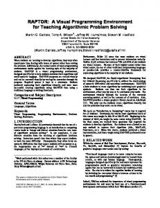
2.2.3 Integration There are three main components of a tool for run-time inspection of software. Firstly, the tool needs to obtain traces from a file or generate them from an actual executing program under inspection. The granularity of the traces that need to be obtained will determine the instrumentation that will need to be used by the tracing 12
component. The second component is the run-time inspector. It takes the traces obtained by the tracing component and “processes” them into something significant that can be visualised. Finally there is the visualisation component. This is the end product of the run-time inspection. In this component, the “processed” traces are displayed on the screen for the user to visualise the behaviour of the program during its execution. This is depicted in Figure 1 where the traces obtained by the Tracing Component are forwarded to the Debugging Component, for processing, and finally to the Visualisation Component to be displayed.
Figure 1: Components comprising a visualisation environment
It is important to integrate these three components in a centralised environment. The rationale behind our belief is as follows. Firstly, it ensures that one of the fundamental rules of object-orientation is maintained: abstraction. By combining all three components into one unit, we are able to hide away the unnecessary details of the run-time inspection from the user. This allows the user to concentrate on the more important aspects of the inspection process, which is to understand the functioning of the program and uncover errors. Our view is substantiated by Kölling [22]. Secondly, it facilitates the task of the user by not forcing temporary files that could potentially be misplaced, corrupted or deleted, on the user. Finally, 13
with less user interaction, integration can lead to a more efficient inspection process with only one single task to perform from the point of view of the user. Another tangent of integration that is worth considering is the integration of the views within the user interface of the tool. This is particularly relevant to the runtime inspection of concurrent programs because many of the concurrency issues are tightly coupled. Depiction of these issues in a centralised user-interface is three-fold. Firstly, it ensures that the aspects of interest of concurrency are adequately depicted. Secondly, it allows the user to relate more closely with the various concurrency issues but also expedite understanding of the nature of the thread interactions. Finally, it allows for more powerful associations to be made between the animation of the program during its execution and the actual implementation of the program. This will, we believe, shed light on the particularities of the relationship between the various entities executing within the program.
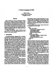
2.2.4 Non-Invasive A run-time inspection tool should not require the program under study to undergo any modifications prior to visualising its execution. Typically, tools that are invasive in their approach are generally not flexible or portable. Let us take the example of a sort routine that we want to animate from a program. One of the aims of such a task may be to expedite the comprehension of a fundamental concept, in this particular case, sorting. We start by annotating a portion of the program to graphically illustrate the sorting procedure on the screen. The outcome of this annotation is a graphical depiction of the sorting as illustrated in Figure 2.
14
Figure 2: Examples of sort routine animation (from [23])
This program, however, is limited to animating a sort routine. If on the other hand, one wanted to animate the creation of objects, another portion of the program would need to be modified and probably reverted back from the previous modifications. This indicates that annotating a program is invasive and may lead to errors being introduced to the program. We discuss the issues associated with this approach next. Modifying a program in order for it to be visualised and animated should be avoided. This can lead to a cyclic chain of modifications and regressions of procedures that can be costly in the end. Firstly, modifying a piece of code may allow further errors to be inserted into the program, thus hindering the essence of the debugging or inspection process that one was trying to achieve in the first place. Secondly, in the case of run-time inspection for the purpose of program understanding, this process requires the user to possess or have access to the source code of the program. Thirdly, and quite importantly in our view, it requires the user to understand the code well enough to be able to annotate it with further code. For these reasons, it is imperative in our view that a run-time inspection tool not need modifications to the underlying source code of the program that it aims to observe. In fact, we believe that the less access that a visualisation environment has to the source code of the program under inspection, the better. We relax our constraint for source code traversal and animation.
15
2.2.5 Object Support In a pure object-oriented program, classes would be designed, and objects instantiated from them, to model an abstraction of a real-world scenario. These objects would have attributes describing their states and methods to demonstrate their behaviour. Methods from one object would interact with methods from the same object as well as with methods from other objects in order to achieve some program dynamics. In our view, it is fundamental that programmers be presented with an explicit view of the set of objects contained within the program. Objects, typically, undergo many changes in their states during execution. We use the term state loosely here to represent the fact that objects are constantly in transition: they go from being created; to being idle; to being accessed; to invoking methods on other objects; and finally to being terminated. In particular the creation and destruction of objects during execution should be clearly pointed out. Similarly, depiction of invocations both on and from an object is crucial in gaining proper understanding of how the program behaves at run-time. It is important to find out how the objects are accessed. In this regard, the user should be presented with the methods that access the various objects. It is also useful, from an object-oriented perspective, to observe the coupling2 of objects within the program and particularly, how often an object is accessed. It is useful to note here, however, that the previous remark should not imply complex software metrics. A simple visual cue similar to a flowchart, for example, supported by some time dimension, will suffice. Similarly, it would also be useful to note how often methods from a particular object access other methods. It could also prove useful to show the behaviour of the object during invocations. Information pertaining to the length of time (time is used loosely in this statement) that the object is accessed, especially if it is being accessed by only one other object, may also be useful to the user. It is important to note here however that while graphical depiction of objects is desirable, as outlined previously in section 2.2.1, it is not a mandatory requirement.
16
Furthermore, another tangent justifying the need for object support within a visualisation environment is as a basis for learning. Once again, work by Kölling [22] supports our claim. A clear depiction of objects can assist users gain an appreciation of the design model and relate more closely to how the objects interact with one another in the code. Ultimately, it should assist programmers in improving their understanding of the code. This is of particular importance to programmers who did not design the code but wish to use the visualisation tool to further their understanding of the program.
2.2.6 Concurrency Support Concurrency is often described as the ability of two or more processes to execute simultaneously. Processes are generally perceived as being a sequential block of code, or even a sequential program in its entirety, that executes a sequence of statements [24]. Processes may in fact contain further processes. There are two ways in which threads communicate to perform their tasks; they either use shared variables or message-passing. Threads are defined as light-weight processes that can execute independently of the main core of the program. A visualisation tool that aims to depict concurrency needs to have an explicit portrayal of threads within its environment, as a minimum requirement. Regardless of whether concurrency is achieved through shared variables or message-passing, the threads therein communicate by invoking some methods on one another. Concurrency adds a further layer of complexity in that these methods’ invocations can be in the form of an asynchronous or synchronous method call. The visualisation environment should be able to clearly differentiate between these two invocations.
2.2.7 Standard-Based Stasko and Kraemer [10] state that: “ … displays are most useful when they closely match the mental model that the programmer/analyst forms through the process of program comprehension”. Indeed, it is advisable to base the visualisation upon an interface that 2
Coupling describes how closely interconnected the methods and objects are within a class. Good object-
17
closely resembles an existing standard notation and one with which the user is familiar. The main rationale behind this statement is that it does not necessitate any learning curve and as a result is likely to increase acceptance of the environment. This is particularly true if the notation chosen is similar to a notation used by the programmer for the design of similar programs. Furthermore, in general people dislike learning a new paradigm particularly if there is the perceived notion of a lack of benefit in the long run in doing so. Similarly, adhering to a well-known notation by the programmer is also helpful, as it allows the programmer to draw upon existing cognitive skills acquired. This argument is valid even if the programmer is not the architect of the software under study. Research has shown that we learn by building associations with the subject at hand [15]. Similarly, programmers who are familiar with a particular notation will find it easier to draw upon existing mental links that they have developed with the notation over time.
2.2.8 Platform Independence With the emergence of object-orientation, many of the traditionally procedural languages, such as Pascal and COBOL, to name just two, have adopted the concept and we have witnessed the introduction of Object Pascal and Object COBOL in recent years. Furthermore, owing to the complexity of newer applications, such as weather forecasting, stock market predictions and complex graphic rendering tasks, many traditional sequential languages, such as Visual Basic and C/C++, have embraced the multi-threading paradigm. The impact of these changes is that implementation of concurrent object-oriented software is no longer confined to a select few languages. In the case of software visualisation, platform independence implies ensuring that the visualisation model is applicable to a wide range of platforms. Additionally, we advocate that the concepts that are being portrayed by the model should be oriented practice dictates loose coupling.
18
sufficiently abstract to facilitate the implementation of the visualisation model using a wide range of programming languages without any loss of information between the various implementations. More importantly, it should provide a direct mapping of the information to the user. In other words, the concepts that a user sees on one platform should be identical to be concepts available on a different platform. The above notion is successfully illustrated in emerging languages in the form of byte code using an abstract or virtual machine. An excellent example of the latter is a project by Gough [25]. In his project, he has defined the notion of an Abstract Stack Machine that allows code to be compiled therein and executed successfully with no loss of functionality on both the Java and .Net platforms.
2.3
Requirements for Concurrency Support
The previous section outlined the requirements for a visualisation environment for the depiction of concurrent programs at run-time. This section focuses on the concurrency concepts that need to be illustrated in order to fully depict the dynamic execution of multithreaded object-oriented code. Multithreading adds further layers of complexity in terms of program comprehension and this is particularly problematic to novices. The first three aspects of concurrent programs that need to be illustrated are objects, threads and method invocation, as these constitute the building blocks of any multithreaded program. Furthermore, thread interleaving also needs to be explicitly depicted as it demonstrates the non-deterministic nature of threads. Synchronisation, monitors and mutual exclusion also need to be portrayed as these mechanisms are not easily understood by programmers and their inclusion in a visual environment would greatly assist in elucidating these concepts. Additionally, we believe that the novice concurrent programmer will benefit from the illustration of exceptional behaviour within the program, as the semantics of exceptions is not generally understood. Finally, one of the goals of this research is to fully represent the safety and liveness issues that may occur during a concurrent program’s execution. In effect, these concurrency issues are triggered by a
19
culmination of several of the key concurrency concepts mentioned previously and depiction of these issues would be desirable.
2.3.1 Depiction of Objects A class is a complex entity. It provides a particular abstraction of the real-world that one is interested in modelling. In particular, it defines the behaviour of this particular abstraction based upon a set of rules. These rules are provided by attributes and methods encapsulated within the class. An object is an instance of such a class. Classes are typically regarded as generic, defining the common behaviour that the real-world entity possesses, while objects are more specific and provide a concrete example. In order to fully appreciate the dynamics of a program, a programmer will seek to be presented with all the objects that exist within the program during execution. It is equally as important to depict objects that are active as those that are inactive or have ceased to exist. Depiction of an inactive object, especially the timing of the object’s destruction, is very important as it can point to a fundamental flaw in the logic of the executing program. In fact depiction of an object that has suddenly become inactive or has ceased to exist may shed more light on the functioning of a program than the depiction of an active object. It is also important to depict the timing of object creation and deletion within the execution, even though the time stamping used is not absolute but merely relative to some logical sequence of events. Many concurrency concepts, such as dormancy and deadlock, rely heavily upon the order of event occurrence. Equally important is the notion of unique object identification. The environment should display the object’s name if it is present within the traces. It is also useful to show the class from which the object has been instantiated together with a unique identifier for the object. The latter would make objects belonging to the same class easier to differentiate. 20
2.3.2 Depiction of Threads Threads are the building blocks of concurrent programs. They enable new processes to execute independently from the main body of the program. In many languages, threads are defined as objects. They are uniquely identified and have a name associated to them. They have internal states and a priority mechanism to manage the order of their execution. Typically, a thread will undergo many changes in its internal state during its lifetime. Threads are inherently dynamic and as such this activity needs to be depicted as it has a major effect on the state and behaviour of the program and helps in program understanding. As in the case of objects, it is useful and important to depict the state and behaviour of threads. It is crucial to show the creation of threads explicitly in the visualisation as the behaviour of the overall program could change dramatically from this point forward. It is equally important to show the destruction of threads. Furthermore, the environment should globally depict the activities of all the threads during execution. This is particularly useful if the activities of one thread can be viewed in the context of the activities of other threads executing within the program. Moreover, illustration of the state of each thread, be it active or terminated, may shed light on problems relating to the execution of the thread. Thread local storage is not depicted as this is an advanced concept and one that is more related to debugging than program comprehension. In essence, the performance of the program is based on the sum of actions of all of its running threads cooperating and sharing resources with one another. Visualising and animating this execution is the foundation in understanding the program and ultimately uncovering errors in the logic therein.
21
2.3.3 Depiction of Messages In a sequential environment, objects communicate by exchanging information between each other using communication channels. For example, a “mouse” object broadcasts to all listening objects that its right button has just been clicked. This does not require any confirmation from any of the subscribing objects and the mouse object continues with its normal execution. Messages can also be used to delegate an activity unto another object. For example, in response to the mouse click event, the “mouse” object may ask the “button” object to update its status to “pressed”. In this particular instance, the “mouse” object needs not know the internal operation of the button object. It is sufficient for the mouse to have instructed the button to update itself. In a concurrent environment, in addition to the two scenarios defined above, a call to a method can be synchronised. A synchronised method differs from a normal method call in that, during the synchronised method call, no other activity that has the potential to affect the state of the object is able to execute. These three variations of message calls are interesting and one would expect the programmer to be presented with such information in the visualisation interface. Normally, in the case of an invocation, the programmer would be interested in determining the object that initiated the call (the caller object) and the intended recipient of the method call (the called object). Typically, the information that will need to be visualised is the caller object, the called object and the name of the method called. Additionally, the type of method invocation is also important.
2.3.4 Depiction of Thread Interleaving One of the main characteristics of concurrent programs is that threads execute in a non-deterministic manner; that is, one cannot predict the precise order of execution of the threads within the program. This represents a major problem for programmers: if one cannot predict the order of execution of the threads, then one cannot foresee the behaviour of the program. This situation is as much of a 22
problem to the programmer writing the code as it is for the programmer attempting to understand or debug existing code. Mechanisms exist to control the order of execution of threads and these are discussed in the following sections. Owing to the potential for conflict, there is also a need, within the visualisation environment, to support the depiction of thread interleaving. Thread interleaving can be illustrated within a visualisation environment by making use of time based mechanisms to depict the delay in method invocation. Precise time stamping is often used and it has the advantage of clearly specifying the time of occurrence. However, simple graphical techniques that provide some visual depiction of interleaving relative to some arbitrary time factor can be as effective, particularly for the purpose of program comprehension and in cases where the absolute time of occurrence is not required.
2.3.5 Depiction of Synchronisation and Conditional Synchronisation One mechanism for controlling the order of execution of threads in a program is the use of synchronisation. Synchronisation provides exclusive access to threads that need to access an object’s internal data. In so doing, the actions of the thread on the particular object appear to be one single non-divisible action. Depiction of synchronisation is useful and important, especially to a novice concurrent programmer, as it differs from non-synchronised invocations on the object. Therefore, illustration of synchronisation in a visualisation environment should be vivid and explicit. Conditional synchronisation describes a situation whereby a thread is blocked until a particular condition holds. Occasionally, however, due to the condition being omitted or incorrectly specified, a situation that the programmer perceives as conditional synchronisation results in non-blocking synchronisation. The ability for the visualisation environment to highlight the three variants of synchronisation described above would be of assistance to the novice concurrent programmer.
23
2.3.6 Depiction of Object’s Monitor and Mutual Exclusion A monitor protects the internal components, data and methods of an object by controlling the way that executing threads access these components. Threads access critical sections of objects by temporarily acquiring the lock to the object’s monitor. As stated by Kramer [13], only the monitor access procedures wait, notify and notifyAll, can read and modify data encapsulated by the monitor. A monitor is a useful concept in concurrency and its depiction, particularly the locking mechanism involved in a thread acquiring an object’s monitor, is crucial in expediting program comprehension and a vital addition to a visualisation environment. It is as useful, in a visualisation environment, to depict the monitors that a thread currently possesses (owned monitors) as it is to depict the monitor that it is waiting to acquire (contended monitor). The use of monitors guarantees mutual exclusion by protecting the data encapsulated within an object. Mutual exclusion refers to a technique whereby access by executing threads to a critical section of an object is controlled in order to avoid undesirable modifications to the object’s data. The locking and unlocking of object monitors during mutual exclusion is important and useful to the programmer and needs to be explicitly and adequately depicted in the visualisation environment. Equally useful is the illustration, to the programmer, of activities occurring within the object while the lock is in place during mutual exclusion.
2.3.7 Depiction of Exceptional Behaviour In an ideal world, properly designed and written software does not crash and always completes successfully. However, despite the best intentions of programmers, external modifiers, such as input, output, disk access and networks, have a negative impact on programs and can cause program failures. Such unforeseen failures in the environment are termed exceptions, because they are, in fact, exceptions to the normal behaviour of programs.
24
When an exception occurs in a sequential program, it is either dealt with directly by the affected method or delegated to another method higher up in the calling sequence to be handled properly. An exception that is not handled properly will escalate along the calling sequence until it reaches the root where the entire program is then halted. In a concurrent environment, due to the presence of multiple threads executing, the situation is different. An exception occurring within a thread may not force the termination of the entire program but instead only that particular offending thread. This can have dire consequences for the programmer as it may be not be apparent that the thread has been terminated until a long time after its death, if at all. This calls for mechanisms to be provided to the programmer, not only to depict the exact location of the occurrence of the exception, but also to follow the progression of the exception along the sequence of post-exception method calls until the point that the exception is either handled or the thread terminated. Visualisation, in this case, can serve two purposes. Firstly, it will indicate to the programmer the presence of a failure in the program, whilst showing that the rest of the program is still executing. This is a situation in which a programmer without much concurrency experience will benefit the most as he or she will not be accustomed to such circumstances. Secondly, it should shed light on the mechanics of an exception; one of the grey areas of programming.
2.3.8 Depiction of Safety and Liveness Issues A safety property asserts that the internal components, in particular data, of an object are not accessed in any manner that compromises the integrity of the object’s state. Safety is normally achieved in a concurrent program with the use of synchronisation constraints and mutual exclusion. A liveness property asserts that events comprising the program’s execution eventually have an opportunity to proceed. Safety and liveness are tightly coupled and a right balance must be struck between the two. Maximising safety may lead to liveness violations. Conversely, upholding liveness may lead to safety breaches. 25
Maintaining safety in a concurrent program involves ensuring that, at most, one thread is allowed to modify an object’s data at any time and that no race condition exists. A race condition is defined as the situation whereby the arbitrary interleaving of threads results in the access and modification of a shared data item by multiple threads in a non-deterministic manner and where the final value of the data item depend on the order of execution [13, 26]. Proving the absence of race conditions in a concurrent program is a non-deterministic polynomial (NP)-complete problem [26]. Visualisation can assist in demonstrating that no actions by threads on the program have the potential to breach the safety property of the program, but visualisation will not prove that the program is safe. The visualisation environment, in this case, will illustrate the synchronisation routines (described in §2.3.5) and illustrate the acquisition of the object’s monitor and mutual exclusion (discussed in §2.3.6). The liveness property in concurrent programs is concerned with ensuring that requests for shared resources are eventually honoured. One of the most common liveness issues is deadlock. A deadlock occurs when all the threads executing within a concurrent program are blocked, waiting for resources from other threads or on some conditions that will never occur. Aside from deadlocks, liveness implies adopting a scheduling policy that ensures fairness in the execution of a set of eligible actions. Two problems that may arise as a result of an unfair scheduling are contention and dormancy. Contention occurs when a thread fails to obtain CPU time. This can be due to a scheduling problem: a thread is assigned a lower priority than other threads; or a fairness problem: waiting threads are placed in a pool and are woken up arbitrarily. Dormancy occurs as a result of a non-runnable thread that fails to become runnable. This is normally due to a thread set on a condition variable that is never met. Dormancy can also hide a synchronisation problem, whereby the execution of threads is interleaved in such a manner that the condition on which a thread must wait is evaluated before the thread has even started waiting, resulting in the thread missing out on a chance to execute. Visualisation can help in detecting liveness failures by providing a history of the execution. In the aftermath of a deadlock, for example, the event sequence is halted, 26
indicating the presence of a failure within the code. Depiction of thread interleaving and condition synchronisation can assist in detecting deadlock as well as dormancy issues. Contention issues, however, introduce additional requirements on the visualisation tool, as they are strongly linked with fairness in the concurrency model of the implementation. Fairness is, in turn, related to the scheduling model of the underlying platform, as the latter determines which one of the waiting processes gets a chance to execute next. However, some degree of fairness can be moulded by the programmer by introducing predicates to ensure that every process has a chance to execute. Visualisation can be used to detect patterns in the model during execution and project them to the programmer. The above discussion describes scenarios where visualisation can assist in detecting safety and liveness issues within a concurrent program. It also refers to the relationship between the various types of concurrency issues. Because synchronisation predicates impact upon the safety properties of the program, while the order in which synchronisation is achieved impacts upon the liveness properties of the program, there is a need for all concurrency issues to be depicted within a unified environment.
2.4
Summary
This chapter discussed the desired characteristics of a visualisation system that is suitable to illustrate the execution of concurrent object-oriented programs. In particular, it has identified the needs of novice concurrent programmers. These programmers are characterised by their analytical skills in a sequential environment. However, they are novices in the context of identifying patterns in concurrency. Consequently, their needs are somewhat different from other user groups. An overview of the main discussion of the requirements of a visualisation environment from this chapter is provided below. These requirements can be summarised as below: 27
1. Graphical – The visualisation environment should be graphical in order to illustrate the complex interactions within the execution and to take advantage of the cognitive skills of the novice concurrent programmer. 2. Easy of use - The environment should be simple and intuitive and provide adequate secondary notations so as to involve the programmer in the learning process. 3. Integration – The tracing, inspecting and visualising components should be integrated within the environment. Furthermore, all the views within the environment should be unified in order to improve understanding and acceptance of the environment. 4. Non-Invasive – The environment must not require the program under study to undergo any changes in order to be visualised. In fact, the environment should not require access to source code and should be able to work with compiled components. 5. Object support – Object support is a sine qua non requirement of the visualisation environment. The basic object support should include object creation and deletion. Furthermore, it should also support depiction of object interaction and structure. 6. Concurrency support – The question asked here is: “Is concurrency supported within the environment?” The environment should provide explicit portrayal of threads and their activities during execution. 7. Standard based – The environment should draw upon existing well-known standards to take advantage of existing cognitive and analytical skills of programmers.
28
8. Platform Independence – The concepts defined by the model should be abstract. The environment needs to be able to execute on various platforms with almost no modifications to the underlying concepts. In addition to the above requirements on the environment, this chapter also discussed requirements for the support of concurrency. In particular, the question that was asked was: “How are the various entities represented?” These are summarised below: 1. Depiction of Objects – There must an appropriate graphical depiction of objects within the visualisation environment, whereby basic aspects such as the name and unique identifier of the object is provided. Furthermore, the base class as well as the type of the object should also be specified. 2. Depiction of Threads – Threads must be depicted graphically, including, if present, the thread’s name and its unique identifier. Furthermore, the state, priority and activity of the thread during execution also need to be explicitly illustrated. 3. Depiction of Messages – Communication between the various entities comprising the executing program need to be explicitly demonstrated. Message depiction also needs to include the originator and intended recipient as well as the message’s name and type. 4. Depiction of Thread Interleaving – Representation of the interleaving of threads is not only useful, it is also important in improving comprehension and engaging the programmer in the program execution. 5. Depiction of Synchronisation and Conditional Synchronisation – Illustrating the concept of synchronisation and the subtleties associated with condition synchronisation is useful in grasping a proper understanding of ensuring safety within the program.
29
6. Depiction of Object’s Monitor and Mutual Exclusion – Depiction of monitors and mutual exclusion - in other words, blocking mechanisms to protect critical sections of objects - is crucial to allow the programmer to gain some insight into the complexities of concurrent programs. 7. Depiction of Exceptional Behaviour – The programmer will benefit from an exposure to the effects of failures occurring during execution. Of particular importance are the recovery mechanisms that are initiated following a failure. 8. Depiction of Safety and Liveness Issues – The environment should emphasize on the comprehensive set of concurrency issues. These issues are interrelated around the synchronisation predicates used and their order of execution, and represent the culmination of the aforementioned concurrency concepts. The requirements outlined in this chapter will serve as means for reviewing existing visualisation environments, from the literature, in the next chapter.
30
Chapter 3
TOOLS FOR VISUALISING CONCURRENCY “Il ne faut pas apprendre à écrire mais à voir : écrire est une consequence” Antoine de St Exupéry
3.1
Introduction
This chapter explores existing software tools that address the visualisation of concurrency. A number of surveys have discussed the issues of software visualisation, namely Kraemer and Stasko [10], Kraemer [11] and Ellershaw and Oudshoorn [27, 28]. The difference between these surveys and our study is the approach taken and the criteria used for assessment. These authors, in addition to providing a comprehensive survey on the state of the art in software visualisation, enlighten the reader on the merits and traps of software visualisation particularly in the area of multithreading and parallelism. Stasko and Kraemer state that “the role of visualization in program comprehension is that of facilitator” [10] and that an effective visualisation can expedite comprehension of the problems and uncover details that would otherwise be buried deep within the execution. The approach taken by Stasko and Kraemer [10] is to draw a comprehensive list of issues pertaining to the visualisation of parallel programs for program comprehension and substantiate their arguments by discussing the functionality of the Parade visualisation tool. One interesting comment in their survey, while discussing animation of concurrent programs, is: “…events that might have been concurrent can be shown concurrently in the display” [10]. This brings forth a new perspective of software visualisation, that of software prediction. However one needs to be careful with predictions so as not to confuse the user with what is happening and what can happen.
The approach taken by Ellershaw and Oudshoorn [27] is closer to a taxonomy of visualisation systems that addresses the different approaches that these visualisation systems take to highlight various aspects of program visualisation. They conclude their survey with an overview of the main focus of each visualisation system and the programming and computing aspects that are highlighted therein. The most pressing question, presently, is: What visualisation environments should be surveyed? Our initial approach was to identify environments that were often referenced in the literature as this was an indication that these environments had some merits. Additionally languages that supported the requirements outlined in Chapter 2 were also considered for evaluation. In this regard, we not only considered environments that specifically addressed all the issues that we raised but also showed the potential to address them in future releases or else possessed characteristics that had been overlooked by their respective creators. This initial survey generated two lists of visualisation environments. The first list offered those environments that were the most important to our survey as they more closely matched the requirements set out in chapter 2; they included: Javis, Javavis, Jinsight, Jitan and Parade. The second list contained environment that did not match our initial criteria as closely but still had some features or concepts worthy of consideration. This list includes Visual and Jeliot. We now review the selected environments according to the requirements established in Chapter 2.
3.2
Javis
JaVis [29-31] is a tool for visualising and debugging concurrent Java programs. The visualisation is performed using Sequence and Collaboration diagrams, based on the UML.
32
3.2.1 Requirements for the Environment 3.2.1.1 Graphical
Javis possesses a rich graphical interface. Its environment is integrated within the UML CASE tool, Together [32]. The entire execution of the concurrent program is animated and displayed in a graphical user interface (GUI). Javis allows the user to zoom in on a selected portion of the executing program, while the entire program execution is iconified on the left hand margin. It has a simple GUI, making use of the Sequence and Collaboration diagrams from within the UML Interaction Diagrams family.
3.2.1.2 Ease of Use
The visual interface of Javis is based on Sequence and Collaboration diagrams, the two diagrams from the UML Interaction diagram family. Javis, therefore, offers a degree of familiarity to users who are already accustomed to the UML paradigm. Furthermore, Javis makes some simple and straightforward extensions to UML. These extensions are well-defined and documented and should not require any further learning prior to the use of the tool. Overall, Javis is an easy tool to use, albeit showing some ambiguity in the depiction of a synchronised method.
3.2.1.3 Integrated
Javis is a fully integrated environment comprising of a tracing and a visualising component. Collection of the traces by the Tracing component is done in a postmortem fashion. The tracing component within Javis is also used to detect errors, mainly associated with deadlocks, inside an executing concurrent Java program. The traces, thus obtained, are used to replay the execution of the program at a later stage within the Visualising component. To facilitate dynamic replay, the traces are delivered in the form of a script. The visualisation component is comprised of a Sequence and a Collaboration diagram. This component is integrated within the Case tool Together. Having the visualisation component integrated within the Case tool allows Javis to fully utilise 33
all the functionalities of the Case tool as well as possessing a centralised interface. Most importantly, Javis is then able to abstract the entire execution and provide an overview of the executing program on the left column. Furthermore, Javis provides tabbed views, where different scenarios from the program execution can be animated. A screenshot of Javis can be seen in Figure 3.
Figure 3: Screenshot of Javis – (from [31])
3.2.1.4 Non-Invasive
Mehner [29] is one of the main advocates of upholding the non-invasiveness properties in a software visualisation environment. The Javis environment makes judicious use of tracing to ensure that the source code of the program is not altered in any way during the events gathering phase. This is mainly achieved using the API from the Java Platform Debugger Architecture [33] (JPDA) and a Tracer program within Javis. The tracer program can be attached to an already running program or can start a new program. The debugged program can either be running locally or
34
remotely from the tracer. The tracer mainly gathers information about the blocking of threads in the program, leading to a potential deadlock.
3.2.1.5 Object Support
Javis, being an integral part of a UML Case tool, provides full support for the depiction of objects. Object creation is explicitly depicted in the view and a call to the constructor is illustrated by init. In addition, the objects are properly labelled with the class name and a unique identifier.
3.2.1.6 Concurrency Support
Javis provides good support for concurrency within its environment. Threads and their activities are suitably depicted both in the sequence and collaboration diagrams. In particular, it is able to show the synchronisation and locking of threads within the program.
3.2.1.7 Standard Based
Javis uses a well-known modelling language, UML, as the basis for its visual interface. This allows Javis to draw upon the rich syntax and semantics that UML offers. The justification that Mehner and Wagner [30] offer for the choice of UML is that it is “well suited for modelling concurrent systems. It can describe multiple flows of control in structure diagrams as well as in behaviour diagrams”. More importantly, though, as stated in [29], the main aim is to integrate the visualisation into a modelling language that supports the software lifecycle as it not only increases acceptance but also expertise with the environment.
3.2.1.8 Platform Independence
Javis is implemented in Java and uses the JPDA as the conduit to gathering the traces. This allows Javis to execute on any platform that offers an implementation of the Java Virtual Machine. Javis also takes advantage of the rich programming interface of the Java Debug Interface to allow for remote programs to be debugged and visualised. 35
3.2.1.9 Summary
Javis is one of the most interesting software visualisation environments in the literature. It possesses all the necessary requirements to make a suitable visualisation environment. It has a rich user interface and possesses a non-invasive tracing component that supports platform independence. It has an integrated environment, is based on an established standard, which, a priori, appears easy to use. It also fully supports objects and has strong support for concurrency. We discuss the suitability of Javis to support concurrency concepts below.
3.2.2 Requirements for Concurrency Support 3.2.2.1 Depiction of Objects
Depiction of objects in Javis follows closely the format prescribed by the UML standard. Object representation is diagrammatically similar to the UML model and each object is identified by a unique identifier and class name. The Sequence diagram within Javis also illustrates the relevant timing dimension using lifelines and activation bars.
3.2.2.2 Depiction of Threads
Threads are illustrated in Javis similarly to object depiction. Synchronisation between the threads is depicted with the use of the synchronized keyword and it precedes the name of the method call. It is also possible within the Collaboration diagram to animate the locking mechanisms of the threads using two stereotypes and .
3.2.2.3 Depiction of Messages
Invocation of methods in the Sequence diagram follows closely the format outlined in the UML specifications. Mehner et al [29-31, 34] use a solid line with an empty arrowhead to illustrate messages passed between objects. They illustrate a synchronised method by appending the synchronized keyword to the method name. However, as we stated in section 3.1.6, there is some ambiguity in their depiction of 36
a synchronised method. A return from method call is depicted as a dashed line with a stick arrowhead, consistent with the UML specification. The Collaboration diagram provides a richer notation for the depiction of messages. In addition to the normal notation for methods, as stated by the UML specifications, Mehner et al. [29-31, 34] add two stereotypes to represent the locking and acquisition of objects. These two extensions generate one additional notation to the diagram. In order not to clutter the diagrams too much with directed links, Mehner chooses to have a labelled miniature link that describes the collaboration between the objects at that particular time. These edges or links are depicted in green and red in the tool.
3.2.2.4 Interleaving of Threads
Owing to the use of the sequence diagram paradigm to illustrate the dynamicity of the execution, Javis provides an excellent mechanism to animate the interleaving of threads. In accordance with the semantics of Sequence diagrams, objects are depicted from left to right in order of creation and the activities therein are portrayed from top to bottom. Javis further enhances the depiction of thread interleaving by illustrating a change in the flow of control by stacking the activation bar on the right. This is demonstrated in Figure 4 below.
37
Figure 4: Depiction of messages in Javis (from [22])
3.2.2.5 Synchronisation and Condition Synchronisation
Synchronisation is illustrated both in the sequence and collaboration diagrams in Javis by using the synchronised keyword that precedes the name of the method called as shown in Figure 4. However depiction of synchronisation in the collaboration diagram is not as explicit as in the sequence diagram. This is mainly due to the nature of UML collaboration diagrams which are naturally more focussed on the relationship between the various objects than on the succession of events in the program. Javis, however, does not explicitly illustrate condition synchronisation.
3.2.2.6 Object’s Monitor and Mutual Exclusion
Javis does not explicitly depict the acquisition of an object’s monitor within its views. Furthermore, visual representation of the locking mechanism in the Sequence diagram is somewhat ambiguous, because as Mehner states: “…Together does not support shading of activation bars which would have been more intuitive to distinguish between the two steps of the method call”[29]. Therefore, to represent the acquisition of a lock on an object, Mehner decided to use an additional method call with immediate return. Upon return of the message call, which automatically implied that the lock was obtained, then the same method call with parameters was drawn to show the actual method call. In the Collaboration diagram, however, the locking mechanism is much clearer. The collaboration diagram has been extended and two stereotypes,
38
and have been defined to visually depict the acquisition of an object’s monitor. Mutual exclusion is depicted both in the sequence and collaboration diagrams. In the former, it can be seen that no activities are performed while the lock is in place. In the latter, mutual exclusion is illustrated using the directed edges and two stereotypes.
3.2.2.7 Depiction of Exceptional Behaviour
Javis does not support the depiction of exceptions within its environment.
3.2.2.8 Depiction of Safety and Liveness
One of the main aims of Javis is the depiction and automatic notification of deadlocks from within an executing program. To this end, Javis defines some clear and precise mechanisms with the use of a script, generated during the event generation phase, to uncover the deadlocks. The notification of deadlocks is provided in a textual description to the user with the help of a UML note. As pointed by Mehner [29], the deadlock detection mechanism is currently only available to users in the tracing component. However, it is anticipated that the mechanism will be offered in the visualisation component as well in the future. Javis does not, at present, explicitly support any of the other safety and liveness issues discussed in §2.3.8.
3.2.2.9 Summary
Javis supports many of the requirements for concurrency that we outlined in §2.3. In particular, it is quite powerful in the detection and notification of deadlocks in a concurrent program. The visualisation component proposes some interesting extensions to the UML to facilitate the comprehension of concurrency concepts during program execution.
39
3.3
Javavis
Javavis [35] is an educational software visualisation tool that aims to support the teaching of object-oriented concepts in Java for beginners.
3.3.1 Requirements for the Environment 3.3.1.1 Graphical
The Javavis environment is graphical. It uses the UML paradigm to illustrate the execution of Java programs similarly to Javis. The visualisation system uses concepts from the Object and Sequence diagram paradigm from UML to facilitate the animation of software at run-time and engage programming novices in learning Java. It consists of four windows that offer different perspectives of the execution of a Java program to the novice user. The first window, which normally appears on the top left, controls the execution of the debugged program. The window containing the object diagram is situated below the main toolbar. It provides a visual representation of all the objects executing within the program in a tabbed format. The third window contains a standard input and output view of the system; this allows the user to interact with the running program. Finally, there is a window containing the sequence diagram.
3.3.1.2 Ease of Use
Javavis offers a simple interface to its user through its four windows that display various perspectives of the program during execution. The information provided by the visual interface is so detailed that it acts like a debugger. However, unlike most debuggers, it is not threatening and offers solutions rather than waiting for the user to request additional information. In this respect, it builds the visualisation by animating the execution of the software in real-time. Javavis, however, focuses on details; contents of arrays and links are explicitly presented to the user. This information includes, for example, the types of the parameters being observed.
40
3.3.1.3 Integrated
Javavis provides an excellent model of integration based on the model-view-controller design pattern, both in terms of functionality and layout of its interface. The overall architecture of the visualisation system is built on top of the Java Debug Interface (JDI), for event gathering, and uses the Vivaldi kernel [35], to animate the software execution. The JDI is used to collect traces from the executing program as well as providing a platform to interrogate and control the executing program. The Vivaldi kernel provides the rich library responsible for enabling what the authors refer to as the smooth transitions of the animation sequence.
3.3.1.4 Non-Invasive
Owing to the use of the library methods from the JDI, Javavis is able to perform non-invasive collection of traces from the program under study. The JDI framework also allows them to properly interrogate the virtual machine executing the program under study and provide detailed and visually appealing depiction of the arguments and local variables in the program.
3.3.1.5 Object Support
Support for objects in Javavis is one of the best that we have encountered in the literature. Oechsle and Schmitt [35] have given much thought to what needed to be represented and this is clearly shown both in the object diagram view and the sequence diagram view. The object diagram view depicts all the stages in the lifetime of an object – from its creation right through to its destruction as well as the different states through which it goes. This is chiefly because Javavis’s main purpose is as a learning tool for novice programmers. In the Object Diagram view, each object is shown in a separate tabbed window that is updated after the execution of each statement in the program. In the Sequence Diagram view, the various objects interacting with one another are shown from left to right in order of invocation.
41
3.3.1.6 Concurrency Support
The main focus of Javavis is on sequential program representation and therefore it does not yet support concurrency. However, it has some basic support for depicting active threads from within the program.
3.3.1.7 Standard Based
Similar to Javis, Javavis uses the concepts and notation of the UML paradigm. They make some strong claims for the use of UML in a visualisation tool. They state [35]: “We are convinced that a programming language like Java and a modelling language like UML should be introduced and used together. Using UML not only in the design phase of a software engineering project, but also in the understanding, testing and debugging phase may be a good vehicle for students to better understand and get used to UML.” We agree with their claim and believe that the use of UML concepts within their tool assists in forwarding the concepts of object-orientation and program structure to their targeted audience of novice programmers.
3.3.1.8 Platform Independence
The use of library methods from the JDI accentuates the platform independence of their learning tool. And as they state, the JDI has all the necessary functions to enable the tool to be implemented. The Vivaldi kernel, on which the visualisation component is implemented, encapsulates the standard Java2D API. The choice of the JDI and Vivaldi will enable portability of their tool on several platforms with no loss of concepts.
3.3.1.9 Summary
Javavis is an effective visualisation tool for animating Java programs. It has a simple, yet effective, visual interface and provides some useful insights into an executing
42
Java program. Its main limitation, at present, is its lack of support for concurrency. We briefly describe Javavis’s adherence to our set of guidelines from §2.3 below.
3.3.2 Requirements for Concurrency Support 3.3.2.1 Depiction of Objects
Javavis provides an abounding depiction of objects in its two views. In the Object Diagram view, objects are depicted exactly as laid out in the UML manuals. Objects are depicted by a rectangle with the object name in the top portion. Underneath the object’s name is listed all the variables currently defined in the object. These variables either have their values listed alongside their names, if these are readily available. If these variables are object types, a link is drawn between the variable and the object to which they refer. This is depicted in Figure 5. The sequence diagram complements the object diagram and addresses the dynamic behaviour of the object. The objects are depicted as boxes each with a class name and object identification. Object creation is shown explicitly using the keyword. Interaction between objects is illustrated by the use of activations. Lifelines are used when the object is not involved in any activity but still alive.
3.3.2.2 Depiction of Threads
Javavis does not have an adequate depiction of threads. It is able to show the various threads executing in the program by drawing the activation bars and messages between objects in a different colour. There is no mechanism yet to illustrate the creation and deletion of threads, or to show the state of the threads during execution.
3.3.2.3 Depiction of Messages
Method invocations are depicted by a directed edge in Javavis. The technique used is similar to that used in Javis and consistent with the UML specifications.
43
Figure 5: Object Diagram showing the objects executing in the program
3.3.2.4 Depiction of Thread Interleaving
Despite not providing support for concurrency constructs, Javavis can prematurely show the interleaving of threads within the program. Oechsle and Schmitt’s [35] choice of the Sequence diagram to illustrate the dynamicity of the execution makes this possible. The dynamic nature of sequence diagrams in relation to time allows the view to show the order in which the threads are executed.
3.3.2.5 Depiction of Object’s Monitor and Mutual Exclusion
Javavis in its present form is unable to depict the object’s monitor. However, despite not being able to show the locking of the object, the Sequence diagram view gives an indication of the resources mutually excluded during the interaction.
3.3.2.6 Depiction of Synchronisation and Condition Synchronisation
Although Javavis does not overtly support concurrency, indirectly it is able to depict the typical synchronisation of threads. In the example provided in [35], they show how a semaphore can be visually depicted within Javavis. This is, once more, aided by the use of the sequence diagram. However, Javavis does not support condition synchronisation.
44
3.3.2.7 Depiction of Exceptional Behaviour
Javavis is also unable to depict the outcome of an exception from within the executing program.
3.3.2.8 Depiction of Safety and Liveness Issues
Despite not being able to explicitly support threads and concurrency, Javavis is able to depict safety within a program, albeit a sequential program. The main reason for the above is that Javavis is thorough in its depiction of objects and their interactions. This allows spurious changes in the state of an object to be exposed relatively quickly. However, the situation may not be as simple as it appears. Javavis deals primarily with novices, who are characterised by having little or no programming knowledge. The ability to detect failures, especially related to the state of objects or attributes, is acquired after years of experience in programming. Nevertheless, Javavis may be able to offer the novice programmers some insight into a data integrity violation even in a concurrent program, but will most probably be hard pressed to deliver the same verdict in the case of a data race condition. This is mainly due to the fact that Javavis is unable to depict the locking and unlocking of objects by threads explicitly. Javavis is unable to depict dormancy or starvation. Providing support for concurrency within the tool is not the main objective of Javavis.
3.3.2.9 Summary
Javavis does not support many of the requirements that we identified in §2.3. Its main strength is the elaborate depiction the inner workings of objects in sequential Java programs. However, despite not providing much support for concurrency, we found that it had the ability to depict some important concepts of concurrency, such as thread interleaving and synchronisation primitively. More important is its potential to offer some insight into the preservation of data integrity in a program.
45
3.4
Jinsight
Jinsight [36] is a tool for visualising the run-time performance of Java programs. It can be regarded as a visual debugger. Its strength lies in uncovering memory leaks and exploring the behaviour of a program at run-time.
3.4.1 Requirements for the Environment 3.4.1.1 Graphical
Jinsight [36-39] offers a graphical environment that consists of four views: the Histogram view; the Reference Pattern view; the Execution view; and the Call Tree view. One of the strengths of Jinsight resides in the many views that it provides and their navigational capabilities - or as stated by its authors: “navigation makes the collection of views far more powerful than the sum of their individual strengths” [36].
3.4.1.2 Ease of Use
Jinsight is a powerful visualisation tool aimed at professional developers. It is particularly successful at uncovering critical errors in a complex application. However, owing to this outstanding ability to detect failures, we do not consider Jinsight appropriate for anyone but expert programmers. Our conclusion stems from the fact that the views in Jinsight provide a high-level abstraction of the program under study that relies heavily on filtering mechanisms as a medium for abstraction; we believe that these mechanisms are a double-edged sword in a visualisation environment. Filtering demands that the programmer has a clear understanding of what he or she is looking for beforehand. Furthermore, the richness of information provided by the various views will necessitate a substantial learning curve prior to their use. Owing to our target audience being novice concurrent programmers, who have limited exposure to concurrency, the aforementioned characteristics of Jinsight may discourage the programmer from using the environment.
46
3.4.1.3 Integration
Jinsight is another fully integrated environment similar to Javis. Jinsight offers mechanisms to extract patterns from within the execution and allows views to collapse and expand aggregate information relevant to a wide range of software components [36, 37]. This is particularly applicable to the Histogram, Reference Pattern and Execution views where programmers can expand collapse nodes to explore various objects or methods executing. Jinsight does not only integrate the mechanisms for gathering traces, but also integrates its many views to facilitate navigation within the environment.
3.4.1.4 Non-Invasive
Similar to Javis, Jinsight operates in a non-invasive manner to collect traces using a profiling agent and standard JDI code. Generally traces captured by the profiler are of considerable size. Jinsight, therefore, selectively reduces the size of the traces either by filtering or by performing task-oriented tracing where only relevant information about the execution is preserved without affecting the structure and context of the information.
3.4.1.5 Object-Support
Jinsight provides good support for objects. This support occurs mainly in the Reference Pattern view, but also in the Histogram view. The former depicts objects as coloured squares linked together. The Reference Pattern view displays recurrence of patterns within the execution. Thus it allows objects to be grouped by type and reference. Figure 6 provides an example of the Reference Pattern. Objects are represented by a square whereas collections of objects are shown as twin squares. The strength of Jinsight lies in the richness of its navigational and presentation functionalities.
47
Figure 6: Reference Pattern view (from [36])
The example from Figure 7(a) shows objects instantiated from three classes arranged in a tree-like structure. Because some of the objects share the same class, the forest of trees of reference patterns can be collapsed into a single tree without losing too much of the information that the program is trying to convey to the user (see Figure 7(b)). Indeed, Jinsight’s authors state: “we are shifting our focus from individual objects to group of objects, allowing the user to work with a greater degree of complexity” [39].
(a)
(b)
Figure 7: (a) Actual objects and references; (b) Result of extraction (from [18])
Jinsight also uses the Histogram view to visualise the connections among objects as shown in Figure 8. Objects are depicted as coloured rectangles. Colour, in this case, is used to represent several key software metrics relevant to the object. A more 48
detailed discussion of the above can be found at [36]. The strength of the Histogram view, as pointed out by the authors, resides in the rapid detection of hot spots and memory leaks. More detailed information can be obtained from the histogram view by clicking on the object icon in the view. The view follows the entire lifetime of an object, from the time of its creation to its destruction. In fact, an object that has been garbage-collected turns into an outline [36].
Figure 8: Histogram view (from [36])
3.4.1.6 Concurrency Support
The main objectives of Jinsight are in the detection of memory leaks and exploration of system behaviour at run-time. Therefore, despite being able to depict concurrent programs and threads execution, it does not have the capacity to provide much support for concurrency issues and the analysis of their effect per se unless these errors relate to a problem in the two aforementioned areas.
3.4.1.7 Standard-Based
One of the shortcomings of Jinsight, from a novice concurrent programmer’s point of view, is the complexity of its interface. To the best of our knowledge, Jinsight does not derive its views from any modelling language or environment. However, 49
the Reference Pattern view can be likened to an object diagram in UML, while the Execution view, when it has been expanded resembles a Sequence diagram in UML. To its credit, the aim of Jinsight is not to facilitate the comprehension of concurrent Java programs at run-time for novice concurrent programmers but instead to offer as much detailed information as possible regarding a particular error.
3.4.1.8 Platform Independence
Similar to Javis, Jinsight uses the JDI to obtain traces from the executing program using a profiling agent. This feature and its non-invasive approach to trace collection ensure the platform independence of its environment and its concepts.
3.4.1.9 Summary
Jinsight is one of the most powerful visualisation environments that we have encountered. It has navigational and visualisation strengths, particularly with regard to uncovering deeply-rooted errors. It possesses an integrated environment that is graphical, non-invasive and has excellent support for the depiction of objects. However, it has a complex interface that is ill-suited for novice concurrent programmers and does not specifically target concurrent programs for visualisation. We discuss Jinsight’s ability to visualise concurrency concepts below.
3.4.2 Requirements for Concurrency 3.4.2.1 Depiction of Objects
Jinsight’s ability to depict objects in its visualisation environment is rivalled only by Javavis. The depth of the abstraction of objects in the environment, especially in the Reference Pattern view [37] is unparalleled. Figure 9 shows the Reference pattern view. The grey area denotes the beginning of the interaction and contains class objects, denoted by a diamond. A diamond in front of a square represents a group that also includes the class object for that class [39]. Objects are represented as squares with groups of objects depicted as twin squares. The view also offers more detailed description of the object by moving the cursor over the square illustrating 50
the object and the information is displayed in the status line (as shown at the bottom of Figure 9). And as stated in section 3.4.1.5, the tree of objects can be expanded and collapsed at will.
Figure 9: Reference Pattern view (from [39] )
51
3.4.2.2 Depiction of Threads
Similar to Javavis, Jinsight does not depict threads effectively. The Histogram view allows the user to view the method invocation by threads executing in the program. It also depicts the interaction of threads among themselves as well as with other objects. The Histogram view allows the user to determine the creation and destruction of threads in the program, although this depiction is not explicit. However, there is no mechanism to show the various states that the threads go through during the execution. The Execution view also provides information about the threads executing in the program. The Execution view resembles a bar chart that utilises directed burst tracing [38] with a burst being defined as: “a set of trace execution information gathered during an interval of time” [38]. The Execution view allows the execution of the program to be viewed at various granularity levels. This is one of the navigational strengths of Jinsight.
Figure 10: The Execution view (from [38])
While the duration of interaction of the threads is provided, the Execution view does not depict the states that the threads go through. The only state in which threads are depicted is the Running state (along with the thread creation and deletion in the Reference Pattern view).
52
3.4.2.3 Depiction of Messages
Jinsight provides excellent illustration of the method invocations in the executing program. This is mainly achieved in the Execution view, as shown in Figure 10, but also with a different emphasis in the Histogram view as shown in Figure 8. The aforementioned views provide a high-level abstraction of the invocations. However, more information regarding the fields and arguments of the method can be obtained by interrogating the Execution view as shown in Figure 11.
Figure 11: Interrogating the Execution view (from [38])
The Call Tree view provides yet another perspective of the method invocation. In this case, the various methods executing within the program are listed and a numerical estimate of their contribution in the overall execution of the program is noted. This view is particularly useful for error detection and optimisation routines within a visualisation tool as it provides specific information about performance bottlenecks in the program. The Call Tree view is shown in Figure 12.
53
Figure 12: Call Tree View (from [36])
3.4.2.4 Depiction of Thread Interleaving
In spite of its non-committal portrayal of concurrency, Jinsight is able to stoutly depict thread interleaving. The main basis for this is that the Execution view strongly resembles a Sequence diagram and provides a time dimension to the execution, thus allowing precise illustration of the invocation of methods by thread in the view. Moreover, the use of colour in the visualisation provides an expeditious illustration of the interleaving to the user.
3.4.2.5 Depiction of Object’s Monitor and Mutual Exclusion
Owing to Jinsight being primarily a visual debugger, it can provide the user with the identity of the thread currently holding the lock to a particular object. However, this information is not readily presented to the user, who instead must interrogate the Execution view to obtain this information. Furthermore, Jinsight does not explicitly depict the exclusive locking of an object by a thread. However, because Jinsight acts as a debugger, it is able to depict the condition that must hold to guarantee exclusive access to the object’s monitor. Despite this, however, the information is not explicitly presented to the user. As mentioned in section 2.3.6, explicit information especially with regard to the locking procedure of an object needs to be provided to the user. Consequently, Jinsight neither explicitly depicts object’s monitor nor mutual exclusion. 54
3.4.2.6 Depiction of Synchronisation and Condition Synchronisation
Jinsight is not able to explicitly depict the synchronisation of thread interleaving. However, indirectly, this information can be partly reached by careful inspection of the various views in the environment. Moreover, since concurrent execution is so complex with rapidly changing events, but more importantly because of the wide range of abstraction capabilities of the Execution view, depiction of synchronisation and indeed condition synchronisation within the Execution view is impractical. However, aided by the Execution view, the underlying mechanisms behind condition synchronisation is enhanced in Jinsight compared to the other environments surveyed.
3.4.2.7 Depiction of Exceptional Behaviour
Despite being predominantly a visual debugger, Jinsight is unable to explicitly portray the flow of exceptions that occur during the execution of a program. The user can be made aware of the occurrence of an exception by inspecting the Execution view. However, it does not provide a mechanism to automatically follow the path of the exception back along the call trace stack. As we stated in section 2.3.7, this illustration can be crucial to a novice concurrent programmer. De Pauw et al. [36, 37] stress the importance of visualisation, object interaction and navigation as being crucial in facilitating the understanding of complex program execution. However, while it may be apparent to an experienced programmer why a particular thread has stopped executing, this may not be so to a programmer new to concurrent programming. He or she is entitled to ask questions regarding the terminated state of a thread. The best way to answer these questions is to recreate the method invocations of the failed thread.
3.4.2.8 Depiction of Safety and Liveness Issues
In spite of Jinsight’s authors’ [36] claim that it is able to visualise deadlock adequately, we do not believe that it is as effective as Javis, Jitan and Parade in its portrayal of deadlock situations. Javis, in fact, goes one step better and notifies the user whenever a deadlock occurs during the execution. Jinsight is, however, able to 55
depict safety issues - and particularly those related to the integrity of data items more effectively than any other tools that we have encountered. With regard to dormancy and starvation problems, Jinsight’s limitation in illustrating the state of threads at run-time hinders its ability to effectively depict the aforementioned liveness issues.
3.4.2.9 Summary
Jinsight is one of the most powerful visualisation environments that we have encountered in the literature. Its range of capabilities in dissecting a program at runtime is impressive. Its visual environment possesses a rich graphical interface aided by excellent navigational capabilities. However, Jinsight is aimed at a professional and skilled audience. It does not suit our purposes as most of its views entail a steep learning curve from the user and demand a thorough understanding of abstraction and cognitive skills that the novice concurrent programmer may not yet possess.
3.5
Jitan
Jitan [40] is a text and graphical-based visualisation environment aimed at visualising the execution of sequential and concurrent Java programs.
3.5.1 Requirements for the Environment 3.5.1.1 Graphical
Jitan has both a textual and graphical interface to represent the dynamic execution of a Java program. It consists of a number of windows to demonstrate objectoriented and concurrency concepts. One of the windows, the object-graph, contains ellipses and directed edges. Another window gives a textual representation of the current object list. The status window provides an account of the various threads and objects from their state perspectives. Finally, the Thread and Object Interaction window provides a listing of the interactions, in terms of method calls, of the objects and threads active in the program. The graphical view has zooming capabilities, allowing to user to drill into the visualisation. 56
3.5.1.2 Ease of Use
Jitan has a simple interface consisting of both textual and graphical components illustrated in Figure 13. The textual component uses indentation, white space and a colour scheme to clearly illustrate the program’s execution. The graphical component uses standard geometric diagrams, such as ellipses, arcs, lines and circles to visually demonstrate the various entities executing within the program. The overall visual interface has a welcoming feel to it.
3.5.1.3 Integrated
Jitan offers a functional integration mechanism for its visualisation environment. Its trace gathering component is not based on byte-code. Instead, Jitan uses a proprietary format that is based on operational semantics that deals directly with the source code. To illustrate the execution of a Java program, Jitan uses both a textual and a graphical interface as illustrated by Figure 13. These interfaces are integrated within the environment and present two different perspective of the same information to the user.
57
(a)
(b) Figure 13: Jitan's (a) textual; (b) graphical interfaces (from [41])
58
3.5.1.4 Non-Invasive
Owing to a proprietary format based on Java syntactic specification, Jitan removes the need for the debugged program to be instrumented using standard libraries from the JPDA. Instead, the source code is parsed and the textual code is transformed into a structural representation, which is a syntactically correct abstract tree [40]. Attali et al. [40] state that: “Jitan represents every structured object as an abstract syntax tree”.
Figure 14: Part of Jitan abstract syntax tree (from [41])
The semantics specifications described above is written in Centaur, a generic programming environment [40]. Jitan therefore does not interfere with the code and also provides a non-invasive approach to debugging.
3.5.1.5 Object Support
Jitan provides good support for objects. In the textual view, all the relevant information regarding objects is listed. These include the type of the object, its list of attributes, whether or not it is locked and if so, the thread locking it and the object wait set, if the latter is not empty.
59
There is also graphical support for objects and these are illustrated as ellipses. The graphical component also allows the user to look at the state of objects and visualise their interactions within the program.
3.5.1.6 Concurrency Support
Jitan supports the interactive debugging of threads during execution. Threads are portrayed both in the textual and graphical components of Jitan. The textual view gives an overview of the threads executing within the program. In particular, Jitan depicts the status of the thread and its continuation (the stack of successive calls). This interactive debugging of threads extends to interactions between the threads and the objects executing within the program along with any problem that may be raised by such interactions. The graphical component provides a more explicit depiction of threads and their states. In particular, Jitan uses a colour coding scheme in the graphical view to illustrate thread status.
3.5.1.7 Standard Based
Although Jitan uses familiar notations for its visualisation, it is difficult to associate the interface of Jitan to any known standard. To the best of our knowledge, Jitan does not draw upon the syntax of any modelling language that we have encountered. The graphical component of Jitan can be likened to a data flow diagram, especially with its nodes and links.
3.5.1.8 Platform Independence
One of the main strengths of Jitan is its non-reliance on any virtual machine to debug a Java program. To inspect a Java program, Jitan converts the source code of a Java program into an abstract syntax tree using Centaur, a generic programming environment. The latter contains a set of inference rules based on the Typol formalism.
60
Not being tied to a virtual machine allows Jitan to successfully execute on any platform. The use of Centaur within Jitan’s code, may even allow for language independence.
3.5.1.9 Summary
Jitan is a software visualisation tool that is used to inspect concurrent Java programs. It offers a different approach to software visualisation from Javis and Javavis, the two tools described previously. First, Jitan does not use the standard debugging interface, the JPDA, as a mechanism to collect traces from an executing program. Second, Jitan does not adhere to any popular modelling interface, preferring instead to base its visualisation on simple geometric diagrams. We discuss Jitan’s suitability to visualise concurrency below.
3.5.2 Requirements for Concurrency Support 3.5.2.1 Depiction of Objects
Objects are depicted both in the textual and graphical components in Jitan. In the textual component, objects are illustrated by a number of fields: the type of the object; the list of attributes; an indication of the locked status of the object and the thread currently locking it if it is locked; the wait set of the object, if it is not empty; and finally labelling to distinguish objects from threads. Figure 13(a) provides an example of the textual component. In the graphical component, objects are depicted as ellipses. Each ellipse may be connected to other ellipses using directed edges, to illustrate the collaboration between the various objects. The user is also able to zoom in on each object to inspect the state of its attributes. An illustration of the graphical component can be seen in Figure 13(b).
61
3.5.2.2 Depiction of Threads
Threads are also depicted both in the textual and graphical components of Jitan. The textual information provided for each thread includes its unique identifier, the state that it is currently in and the activities performed by the thread, referred to as its continuation in Jitan. At each execution, the instruction list from the continuation is updated and only the instructions that are yet to execute are provided, not the ones that have already executed. This allows the programmer to focus on the next instruction [40]. The graphical view allows threads to be more accurately depicted. Threads are illustrated by a rectangle around thread names. Furthermore, Jitan uses a colourcoding schemed to represent the status of the threads.
3.5.2.3 Depiction of Messages
Jitan uses black arrows to depict the interaction between the object entities in the program. Jitan also optionally uses labels alongside the arrows to illustrate the interaction between the objects further.
3.5.2.4 Depiction of Thread Interleaving
The interleaving of threads is depicted mainly in the textual component of Jitan. More specifically, the Objects Interaction window provides a listing of the threads visiting objects and conversely the objects being visited by threads. Sadly, despite providing much information about threads and their status, the graphical component does not build upon the depiction of thread interleaving provided by the textual component. We believe that it would have been useful for the user to see the graphical depiction of interleaving and draw parallels between the textual (and more static representation) and the graphical view.
3.5.2.5 Depiction of Object’s Monitor and Mutual Exclusion
Depiction of object’s monitor is mainly achieved in the textual view. In the graphical view, Jitan uses three arrows labelled with an “L”, to represent a lock on 62
an object by a thread; a “B”, to represent that a thread is blocked waiting for a lock on an object blocked by another thread; or “D”, to represent a dormant thread. These three thread state are shown inside a circle on an arrow.
Figure 15: Depiction of mutual exclusion in Jitan [41]
3.5.2.6 Depiction of Synchronisation and Condition Synchronisation
Synchronisation is depicted using the three locking predicates described in the section above. The animation of the synchronisation of the threads here is not as detailed and explicit as the one in Javis. The user needs to inspect the visualisation for a while before the synchronisation mechanism becomes clear. It is not as apparent as with a Sequence diagram.
3.5.2.7 Depiction of Exceptional Behaviour
Jitan, in our view, is not able to depict the occurrence of exceptions during the execution. Nor is it able to depict the progression and the impact that such an exception may have on the behaviour of the program.
3.5.2.8 Depiction of Safety and Liveness Issues
The nature of the visualisation in Jitan allows it to accurately portray elements of both safety and liveness issues. Firstly, the textual view, being quite detailed, allows the user to thoroughly inspect an object and its attributes. In particular, the Object view allows both data integrity and race conditions errors to be detected. 63
Furthermore, the graphical view allows for deadlock to be detected, albeit to a lesser extent than Javis. By animating the sequence of locking, blocking and dormant threads, Jitan is able to visualise a cycle in the locking mechanism and hence detect a deadlock within the execution.
3.5.2.9 Summary
Jitan supports many of the requirements that we outlined in Section 2.2. It has an excellent portrayal of objects and threads and their interactions in the Textual view. However, many of the concurrency concepts, such as the interleaving of threads, are not adequately represented in the Graphical view. This, to us, is a shame because graphical representations provide a much richer learning paradigm than textual representations.
3.6
Parade
Parade [42] is one of the earliest visualisation environment to address concurrency issues. It is a flexible environment that allows the programmer to design almost any visualisation interface required to deal with the problem at hand.
3.6.1 Requirements for the Environment 3.6.1.1 Graphical
Kramer and Stasko [10, 11] substantially contributed to the development of guidelines to graphical visualisation of programs and this is clearly reflected in Stasko’s Parade environment [42]. Unlike the other environments that we encountered in our survey, Parade does not have a predefined graphical user interface. Instead, through its adherence to the Polka animation system [43], it provides the programmer with a rich means of creating a custom-built user interface. One such example is the set of views built for the KSR pthreads package [44] as shown in Figure 16.
64
Figure 16: Library of views to illustrate KSR pthreads programs (from [44] )
3.6.1.2 Ease of Use
One of the objectives of the Parade environment is that: “…should support visualizations of many different types of programs from different architectures, different programming models and languages, and different applications”[42]. Stasko [42] also states that the environment should be easy to use and not demand that the programmer be an expert in graphics. From our point of view, Parade is easy to use. However, owing to the first aforementioned objective, whether or not the interface of Parade is user-friendly depends greatly on the type of programs being visualised and the type of interface created by the programmer. Nonetheless, the flexibility of the Polka animation system gives Parade a strong claim for user-friendliness.
3.6.1.3 Integrated
Aside from Jinsight, Parade provides one of the best examples of system integration covered in the literature. Visualisation under Parade comprises three components, namely program monitoring and tracing, visualisation system, and mapping from program execution to visualisation as shown in Figure 17.
65
Figure 17: The three components of Parade visualisation (from [42] )
Parade gathers traces from the executing program by instrumenting the latter to collect the trace. Tracing is performed through the use of the Polka library of visual functions. Bridging the gap between tracing and visualisation is the prerogative of the Animation Choreographer [42]. In addition, the views in the Polka animation system are neatly incorporated to create the overall visualisation environment.
3.6.1.4 Non-Invasive
One of the limitations of Parade, from our point of view, is that it relies on instrumentation to acquire the traces from the executing program. And as stated by Stasko: “the most basic way to gather execution information is to have the programmer hand annotate his or her code with output statements” [42]. Parade also makes use of a parallel communication library, Conch [42], that can be modified to support run-time activation and de-activation of trace production. However, this technique still requires the programmer to turn on tracing in the program. This poses a problem if the source code is unavailable.
3.6.1.5 Object Support
While Parade is not particularly focused on object-oriented program visualisation, we believe that it can accommodate the visualisation of object-oriented programs. This is mainly due to the capabilities of the Polka system that provides an object66
oriented design model to programmers [42] but it also stems from the fact that virtually any program can be instrumented to be visualised under Parade. A view similar to the Function view, depicted in [44], can support the visualisation of objects and their interconnection and activities.
3.6.1.6 Concurrency Support
Parade has strong support for concurrency concepts, similar to Javis and Jitan. Owing to the concurrency and parallel communications library upon which it draws, Parade is able to extract concurrency routines from the executing program. These routines are then passed on to the Choreographer that packages them prior to their visualisation under Polka. Thus, Parade supports the visualisation of many concurrency concepts.
3.6.1.7 Standard-Based
Intrinsically, the visualisation environment in Parade is not based on any modelling standard. However, owing to the versatility of the Polka system, Parade can produce a myriad of views that are customised for the task at hand. Figure 16 has provided us with various examples of views such a static call-tree and a Venn diagram-styled view, among others. Figure 19 provides yet another example of the plethora of views possible.
3.6.1.8 Platform Independence
Parade does not offer much in terms of ease of platform independence. First, it is implemented in C/C++, which requires platform-specific compilation. Second, Polka, the visualisation system upon which it is built, is implemented in C++ on top of X Window and Motif. This restricts Parade to execution solely on Unixbased platforms.
67
Figure 18: The Function view (from [44])
Figure 19: Library of views used to illustrate Conch programs (from [42] )
68
3.6.1.9 Summary
Parade is a powerful visualisation environment that is also flexible in its ability to create views. Parade supports many of the requirements for an environment outlined in section 2.2. Parade is not specifically aimed at the visualisation of objectoriented programs, although it does provide adequate support for the latter. However, Parade provides an invasive approach to tracing and is not platform independent.
3.6.2 Requirements for Concurrency Support 3.6.2.1 Depiction of Objects
Objects cannot be effectively depicted in Parade despite its flexible visualisation interface. In particular, information relating to the class from which it is instantiated, the name of the object (if present) and the unique identifier of the object is not readily available.
3.6.2.2 Depiction of Threads
The Thread view allows the programmer to see the number of threads that exist in the program. The view especially lists each thread as a rectangle in a unique colour, to assist the programmer in distinguishing between the various threads executing. The state of the threads is also depicted within the Thread view, as shown in Figure 20(a), by painting the rectangles depicting the thread. If the thread is running, then the entire rectangle is painted in the colour of the thread. If the thread is idle or blocked, then only half the rectangle is painted. A rectangle is painted black when the thread terminates but its address space has not yet been reclaimed. We believe that depiction of three thread states is not adequate.
69
(b)
(a)
(c) Figure 20: (a) Thread view; (b) Functions view; (c) Invocation History view
The Invocation History view, depicted in Figure 20(c), shows the execution history of threads. In the view, each row represents a thread. The X-dimension represents the execution of the thread in time and flows to the right. The colour of the shadow of each bar matches the unique colour of each thread in the Threads view. The bar is segmented and each segment refers to a particular function in the Functions view, shown in Figure 20(b), and is colour-matched accordingly. The invocation of a function is depicted by a tiny arrow head pointing to the right in a segment in the Invocation History view. The latter also depicts the creation of threads by drawing a dotted line from the segment representing the parent thread to the start of the new
70
thread segment. The joining of two threads is illustrated by drawing a dotted arrow from the joining thread segment to the joined thread segment. The Invocation History view is somewhat confusing. First, as can be seen in Figure 20(b), the different threads cannot be easily distinguished because the colours of the threads are so similar. Second, the same problem occurs with the segments. Third, depicting both the creation of threads and the joining of threads in a similar fashion is ambiguous and causes confusion. It would have been more advisable, in our opinion, to depict the creation in a solid line and the join in a dotted line, for example.
3.6.2.3 Depiction of Messages
Method Invocation is depicted in the Invocation view (Figure 20(b)). However, as mentioned in §3.6.2.2, it is confusing because the colour scheme used in the Functions view does not allow the various functions to be easily differentiated. As a result, the segments in the Invocation view do not provide a clear and unambiguous portrayal of the functions executing. Furthermore, it would have been more intuitive to have illustrated the invocation between the calling function to the called function instead of simply depicting an arrow head.
3.6.2.4 Depiction of Thread Interleaving
The interleaving of threads can be depicted in the Animation Choreographer illustrated in Figure 21. However, it is complex. It depicts the execution of threads ordered in time from top to bottom and animates their interactions.
71
Figure 21: The Animation Choreographer (from [42])
The Functions view, see Figure 18, also depicts the threads executing within a function as filled circles that migrate from one function to the next along the edges. In the Function view, the order of execution of threads is slightly more apparent than in the Invocation History view. However, this is only relative to the threads executing within the function, not in the overall system.
3.6.2.5 Depiction of Object’s Monitor and Mutual Exclusion
Depiction of the mechanism for securing the lock to an object’s monitor and mutual exclusion is performed in the Mutex view, as shown in Figure 22. In the Mutex view, the object’s monitor (or mutex) is illustrated by a big circle. The thread attempting to lock the mutex is represented by a smaller circle, filled in the colour of the thread. When the thread acquires the lock to the mutex, the thread, illustrated by the filled circle, moves inside the big circle and remains there until it surrenders the lock. The Mutex view depicts mutual exclusion and this is highlighted by the scenario in Figure 22 where the thread is in the middle of a move inside the mutex. 72
Figure 22: The Mutex view (from [44])
3.6.2.6 Depiction of Synchronisation and Condition Synchronisation
Despite possessing a flexible user interface, none of the views in Parade [42] or the KSR pthreads [44] depict the synchronisation of threads.
3.6.2.7 Depiction of Exceptional Behaviour
Similar to the other environment surveyed, Parade does not support the depiction of exceptions nor their progression along the stack of called methods.
3.6.2.8 Depiction of Safety and Liveness Issues
Parade is able to depict the occurrence of a deadlock through its Mutex view. However, it is not as apparent as in Javis. The main drawback is the lack of cohesion between the views that Javis and Jinsight particularly possess. As mentioned in [44], in the case of two Mutex views, one view may show that thread 1 holds the mutex and thread 2 waits outside, while the second view shows that thread 2 holds the mutex and thread 1 waits outside. This illustrates the occurrence of a deadlock. However, the user is not told how the program managed to get into such a situation. In Javis, for example, when a deadlock occurs, not only does the user see that two threads are contending for the same lock but the trail of method invocations is also provided explicitly.
73
3.7
Other Tools
In addition to the aforementioned visualisation environments, there are a number of other visualisation tools or algorithm animators that were potential candidates for evaluation but did not make it to the final list. We discuss these secondary tools and the rationale for their exclusion from the main list below.
3.7.1 Visual Visual is a visualisation tool aimed at students to help them visualise thread execution and the behaviour of threads at run-time [45]. Visual executes live but also supports post mortem visualisation as a backup and visualises C/C++ multithreaded programs using its own class library for threads [45]. Aside from the main window (illustrated in Figure 23(a)), Visual provides two windows to display specifics of a concurrent program at run-time. These are the History and Thread Status windows. The History window, as shown in Figure 23(c), provides a history of each thread. Visual uses an intuitive colour scheme to depict the state of threads with various colours indicating the different status of a thread. Tags are also provided to indicate what has happened to a particular thread, such as “Join” (JN), “Semaphore post” (SP) and “Semaphore wait” (SW). The Thread Status window, shown in Figure 23(b) displays the current status of each thread and is updated as the thread status changes. While we agree with the concept, the Thread Status view replicates much of the information that the History view already provides to the user, namely the executing threads and their status. Furthermore, the layout of the Thread status window will make it hard to visualise many concurrent threads executing as these will be appended to the right, thus requiring the use of scroll bars to navigate through the entire thread pool. Moreover, the choice of different icons seems redundant to us if their only purpose is to illustrate a different state as this is already apparent by having each state on one row of the table.
74
Figure 23: The Visual Visualisation System
75
In addition to the two aforementioned views, Visual provides five additional windows to depict mutual exclusion (mutex), Semaphore, Read-Write Lock (RWLock), Barrier and Monitor windows. Furthermore, the views are linked to a source code window as shown in Figure 23(d). Visual provides a powerful mechanism for linking the visualisation with the source code. This should be a useful feature for students as it enables them to form an association between the execution and the code responsible for the execution. Such a feature would not be functional in a fullscale visualisation environment encompassing dozens of events concurrently. Visual introduces interesting visualisation concepts and could have been considered for the main survey. However, we believe that Visual is not a true visualisation environment as it only depicts aspects of an executing program rather than the entire execution. Furthermore, Visual does not specifically target object-oriented languages and has little or no support for the depiction of objects within the visualisation, our sine qua non criterion for visualisation environments. Moreover, Visual depicts C/C++ programs and requires a separate library of threads for execution, hindering its prospect at platform independence.
3.7.2 Jeliot The Jeliot family of program animation environments [46-49] is aimed at the teaching of computer science to high school students. The environment is similar to Javavis, but is aimed at a beginner audience. Jeliot does not assume any computing or programming knowledge [48]. The main goal of Jeliot is to initiate the novice programmer to programming concepts and algorithms. It focuses on data and control flow and provides animation of all aspects of object-orientation. A screenshot of the user interface of Jeliot 3 is depicted in Figure 24.
76
Figure 24: The Jeliot 3 user interface (from [48])
Jeliot 3, depicted in Figure 24, consists of several views animating the various aspects of the source code. The Theater view, pictured on the top right of Figure 24 consists of four areas, namely the Method Frame, Expression Evaluation, Constants and Instance areas, as depicted in Figure 25, to keep the layout consistent. This view animates the source code depicted on the left of Figure 24. Jeliot provides a integrated environment that has strong interconnectivity between the various views. The user is also able to control the speed and flow of the source code animation, even rewinding through animated components. Jeliot does not meet our visualisation requirements as it mainly supports a neophyte audience. However, the main contribution of Jeliot to our cause lies in their thorough approach to visual representation and layout.
77
Figure 25: The structure of the animation frame in Jeliot3
While neither Visual nor Jeliot meet our research goals, the five environments presented in the first part of the chapter all have potential to support the visualisation of concurrency. These five environments are evaluated below.
3.8
Discussion
In this section, we look at the five visualisation environments introduced in this chapter and discuss their effectiveness at addressing the issues proposed in chapter two. We are particularly interested in discussing the level of support that they provide to each of the sixteen requirements posed in chapter two. Of all the visual environments surveyed, Jinsight provides the most graphical environment due to the richness of its various interfaces. Javavis, however, offered the most user-friendly environment, mainly because its objectives are to cater for novice programmers. All five environments surveyed exhibited a carefully integrated visual environment, while Jinsight provided the more comprehensive case due to its task-oriented tracing approach.
Javis provided the most thorough
example of non-invasiveness, mainly because of its judicious use of tracing in conjunction with the JDI interface to capture the traces from the executing program. Jitan also deserves a mention for its unique approach towards trace collection. Most of the environments also had good support for objects with Jinsight and Javavis outperforming the rest. Javis and Jitan had excellent support for concurrency by providing good mechanisms for the depiction of threads and their 78
interaction while Parade provided adequate support in this regard. Javavis and Jinsight, however, did not provide much support for concurrency with Javavis clearly lagging behind. Owing to its UML-based interface, Javis provided the fittest solution based on a common modelling standard. Owing to its use of the JDI and a profiling agent, Jinsight offers a more platform-independent solution to visualisation. Depiction of objects was adequate in all the environments surveyed. However, Jinsight offered a thorough portrayal of objects mainly due to its rich navigational characteristics but also because of its debugging characteristics. Depiction of threads was more effectively achieved in Jitan, where both the textual and graphical views provided an unabridged illustration of threads. Four of the five visualisation environments provided excellent depiction of messages, especially in Javis, Jitan and Javavis, where they were similarly illustrated. Owing to its use of the Sequence diagram paradigm, Javis offered the best depiction of thread interleaving and synchronisation. According to us, Parade provided the best portrayal of an object’s monitor and mutual exclusion. None of the environments surveyed had support for the illustration of exceptions and their progression along the stack of called methods. Finally, only Javis and Jitan provided satisfactory support for a comprehensive illustration of safety and liveness issues. Table 1 provides a summary of the fit to the requirements by the five visualisation environment surveyed. Javis was the closest in terms of adherence to our set of requirements. However, it had no support for the depiction of exceptions and did not provide a complete model for the depiction of safety and liveness issues. Parade was the least suitable for our purposes, mainly because it cannot properly depict objects; it is invasive and did not provide platform independence.
79
Table 1: Comparison of level of support for requirements
Requirements
Javis
Javavis
Jinsight
Jitan
Parade
Graphical
☻
☻
☻
☻
☻
Ease of Use
☻
☻
☻
☻
Integrated
☻
☻
☻
☻
☻
Non-Invasive
☻
☻
☻
☻
Object Support
☻
☻
☻
☻
☺
Concurrency Support
☻
☺
☻
☻
Standard-Based
☻
☻
☺
☺
☺
Platform Independence
☻
☻
☻
☻
Depiction of Objects
☻
☻
☻
☻
Depiction of Threads
☻
☺
☺
☻
☺
Depiction of Messages Depiction of Thread Interleaving Depiction of Synchronisation and Conditional Synchronisation Depiction of Object’s monitor and Mutual Exclusion Depiction of Exceptional Behaviour Depiction of Safety and Liveness Issues
☻
☻
☻
☻
☺
☻
☺
☺
☺
☻
☺
☺
☺
☺
☺
☻
Table 2: Legend of graphical icons used in Table 1
LEGEND
☻
☺
Level of Support
Strong
Moderate
Limited
None
80
3.9
Summary
A survey of some of the visualisation environments that are currently in the literature revealed that none of them fully supported the requirements proposed in Chapter two. Each of the environments that were investigated provided some benefits above the rest in at least one of the raised issues from Chapter two. The intended user group of each of these environments varied as did aspects of software visualisation on which their respective authors deemed more important to focus. However, there were many attributes that were common among most of the tools, such as an integrated graphical environment that is non-invasive in its approach to the collection of traces. The various visualisation environments also recognized the need for objects and methods to be adequately depicted. While some of the environments surveyed were not overly concerned with the visualisation of concurrency concepts at run-time, their respective creators all agreed that some basic needs for the illustration of threads was required. Analysis of the survey revealed that environments that were based on concepts emanating from a known modelling paradigm appear to provide a more user-friendly interface and improve understanding. In the next chapter, we propose our solution for a visualisation environment, employing a notation based upon a standard modelling language.
81
Chapter 4
THE JACOT MODEL “La perfection est atteinte non quand il ne reste rien à ajouter, mais quand il ne reste rien à enlever.” Antoine de St Exupéry
4.1
Introduction
In the previous chapter, various tools comprising the literature in terms of visualization support for concurrent object-oriented programs have been discussed, with a major focus on Java visualisation tools. None of the tools, however, fully met the requirements for novice concurrent programmers, set in Chapter 2. Javis, for example, met most of our requirements. Jitan also had good support for the requirements, while Jinsight and Javavis, had average support. Parade was the least able to meet our requirements. In this chapter, we build upon the strengths and limitations of the above tools and discuss Jacot, a model for the visualisation of concurrent object-oriented programs at run-time. We present, in §4.2, a general overview of the Jacot model. This is followed in §4.3 by a general overview of the UML family of models. In §4.4 a brief overview of the three UML models that we are mostly interested in: the Sequence, State and Activity diagrams, is provided. We only address the concepts and notation that we utilise. An unabridged definition of the UML notation and semantics can be found in [50, 51]. In §4.5, we discuss three-dimensional UML models and their use for dynamic software visualisation. In §4.6, we present the Jacot run-time visualisation language. This is followed, in §4.7, by a comparison with existing work in UML. We summarise and conclude the chapter in §4.8.
4.2
General Overview of Jacot
Jacot is a model for the run-time visualisation of concurrent object-oriented programs and comprises three sub-models: the Sequence model, the Thread State model and the Exception Flow model. The Sequence model is the dominant model within Jacot. It provides a general outline of the structure of the executing program. It is also responsible for illustrating the objects and threads created during the execution of the target program. In this regard, the Sequence model explicitly depicts the creation and destruction of objects along with their activities during the target program’s execution. Furthermore, it provides a vivid depiction of thread creation, deletion and interaction throughout the target program’s execution. The Thread State model provides a graphical representation of the state of all threads executing within the target program. In particular, the Thread State model provides detailed information regarding each thread. This information can be correlated to information provided by the Sequence view. The Exception Flow model outlines the flow of exceptions that may have arisen during the target program’s execution. Depiction of exception generation is twofold in Jacot. First there is the occurrence of the exception and its notification is depicted in the Sequence model. Second there is the depiction of exception flow that is illustrated within the Exception Flow model. We have decoupled the notification of the occurrence of the exception from the depiction of the exception flow because the nature of an exception generation is to provide minimal disruption to the overall execution of the program. This is discussed in more detail in §4.6.3 and §5.4.2.5. One of the findings derived from the survey was that concepts from standard modelling languages appeared to increase usability, improve comprehension and ultimately lead to acceptance of the environment. Furthermore, the inference that can be drawn from the study of Javis and Javavis, two environments based on a 83
standard modelling language, is that the illustration of objects, threads and method invocations, therein, is comprehensive. Consequently, the Jacot model is based on a run-time visualisation language that borrows most of its syntax from the Sequence, State and Activity diagrams paradigm from the UML. The Sequence, Thread State and Exception Flow models, in Jacot, are based upon the Sequence, State and Activity diagrams, in UML. However, part of the semantics associated with the UML syntax is redefined in Jacot, as we deal exclusively with software artefacts at the run-time, not at the modelling stage, as is usually the case. Furthermore, Jacot introduces some additional notation to facilitate the dynamic visualisation of concurrent objectoriented programs at run-time. In the next sections, we provide a background study of UML and elaborate on the rationale behind the use of the three aforementioned UML diagrams as the foundation of our model. We also discuss UML’s suitability to provide support for concurrent object-oriented programs and evaluate its ability to support dynamic visualisation of executing concurrent object-oriented programs.
4.3
General Overview of UML
UML is a “general-purpose visual modeling language that is used to specify, visualize, construct, and document the artifacts of a software system.” [51]. UML consists of nine diagrams that are used to model a system before its implementation. Booch et al. [50] state that UML is process-independent although it is more appropriately used when the application is “use-case driven, architecture-centric, iterative and incremental”. Despite only offering a static representation of the application, the nine diagrams of UML can be classified into two categories of views: static and dynamic. The static view shows the organisation of the objects, participants or components within the application and comprises of the Class, Object, Use-Case, Component and Deployment diagrams. The dynamic view provides an outlook of the behaviour of 84
the application as a result of the simulation of a particular scenario. The word ‘dynamic’ here can be misleading because the actual view itself does not change as a result of one or more events. The view simply illustrates the outcome of a series of actions performed on the application. The dynamic view comprises the State-chart, Activity, Sequence and Collaboration diagrams.
4.4
Overview of Selected UML Models
This section provides an overview of three of the nine UML diagrams that we are mostly interested in. The Sequence diagram paradigm is the one that we draw the most out of, while the two other diagrams, namely the State and Activity diagrams, provide us mostly with the notation. We outline the rationale behind our choice below. The Sequence diagram paradigm was chosen because we wanted to provide a standard environment for our visualisation. In addition, Sequence diagrams have an explicit time axis and are powerful at depicting the interaction between the objects by illustrating the invocation of messages. Furthermore, the combination of the time dimension and message-passing capabilities allow for the interleaving of events to be clearly depicted. The latter is one of the main reasons why the Collaboration diagram paradigm was not chosen for our model although semantically, it provides the same information as a Sequence diagram. Collaboration diagrams are powerful at depicting the relationship between the different objects interacting. However, they do not naturally represent time sequences; instead, they rely on sequence numbers to illustrate the time element of the interaction. The State Machine paradigm was chosen firstly because we wanted to standardise our model and fully utilise UML concepts. Secondly, the UML State Machine provides a structured approach to specifying the state of the entities, which suited our purposes.
85
The Activity diagram paradigm was chosen primarily because we wanted to standardise our model and also because we believe that it is suitable for illustrating the flow of exceptions. Our rationale is threefold. First, as stated in the UML: “whereas interaction diagrams emphasize the flow of control from object to object, activity diagrams emphasize the flow of control from activity to activity”[50]. This is akin to the progression of exceptions during execution. An exception that is not handled or mishandled traverses down the sequence of calling methods until it either reaches a point where the exception can be handled or the bottom of the sequence, where the thread that raised the exception is terminated. Second, Activity diagrams are generally used to depict events that are internal to objects. While exceptions may span across methods in many objects, they are generally perceived to be more internal operations than normal method invocations. Third, activity diagrams offer a clear depiction of the flow of control of operations, which is ideally suited for visualising the progression of exceptions.
4.4.1 Sequence Diagram The Sequence diagram is part of the UML Interaction diagram suite, which consists of the Collaboration and Sequence diagrams. The two diagrams are semantically similar, but each one provides a different emphasis on the information abstracted. As stated in [52]: “a sequence diagram shows the explicit sequence of communications and is better for real-time specifications and for complex scenarios.” Collaboration diagrams are more suited to describing the structural organisation and relationships between the various entities present in the program.
Figure 26 provides a depiction of a
standard UML sequence diagram.
4.4.1.1 Objects
Objects are shown as rectangles with the name of the object centred in the rectangle. In addition, the name of the class from which the object is instantiated is often included, preceded by a colon. The composed name, thus obtained, is underlined to indicate that it represents an instance as opposed to a class. Objects 86
are typically drawn from left to right, in order of instantiation, on the Sequence diagram, along the X-axis.
4.4.1.2 Lifeline
Once an object is created, a lifeline is drawn to illustrate the existence of the object over time. Lifelines are vertical dashed lines and start underneath the object diagram and proceed downwards for the entire duration of the object’s lifetime. The destruction of the object is shown by a large X to illustrate the end of its lifetime. A depiction of an object’s lifeline can be seen in Figure 27(a).
87
Figure 26: Sequence diagram with procedural flow of control (from [51])
88
(a)
(b)
Figure 27: (a) Example of an object’s lifeline and destruction; (b) Example of an object’s activation and nesting of control.
4.4.1.3 Activation
During the object’s lifetime, the object may partake in many interactions with other objects. A tall, thin rectangle, often termed the activation, is used to illustrate the period during which an object is performing an action. The action can either have been initiated by the object or instigated by an outside method. As pointed out in [52], an activation represents: “both the duration of the performance of the Action in time and the control relationship between the activation and its callers”. Indeed, an activation is useful in portraying the shift in the focus of control among the objects participating in an interaction. The top of the activation represents the start of the action, while the bottom represents the completion of the task. UML facilitates the shifting of focus of control that may occur as a result of a call from one method in an object to another or by a call-back from another object by allowing the nesting of activations. Activations can be stacked onto one another on the right up to a certain depth. In addition to the nesting of activations, UML specifies that a portion of the activation may be shaded to further illustrate the focus of control.
4.4.1.4 Messages
Messages describe communication between two objects. UML defines a set of four message format to be used to describe various communications between the objects. A solid line with a filled solid arrowhead is used to depict a procedure call; 89
in other words, a synchronous communication channel. The call to the method blocks until the entire sequence of events contained within the call is completed. A solid line with a stick arrowhead is used to denote asynchronous communication. This is a non-blocking call whereby the sender sends out the message and does not wait for the message to return before proceeding with the next event. A dashed arrow with a stick arrowhead is used to denote a return from procedure call. UML states that the return call may be omitted in a procedural method call. A curved arrow is used to depict a self-call, also referred to as a local call invocation. It depicts a method from one object calling another method from the same object. Messages sent and received by the objects are drawn from top to bottom as time progresses along the Y-axis. By showing the objects along the X-axis and the messages along the Y-axis, the sequence diagram allows the user to clearly depict the order of invocation of methods on the objects. Figure 28 provides an example of the four message formats in UML.
Figure 28: Examples of Messages within UML
4.4.1.5 Threads and Concurrency
There is limited support for concurrency and thread depiction within the sequence diagram. Everything remotely related to concurrency in UML revolves around the concept of active classes and objects. An active object is an instance of an active class and is defined by UML as: “an object that owns a process or thread and can initiate control activity.” [50]. An active object is portrayed graphically as a rectangle with thick borders.
90
Specification of concurrency constraints are done using stereotypes ([50] pp 309320). Associated with active classes are two standard stereotypes: process and threads. UML defines a process as: “a heavyweight flow that can execute concurrently with other processes”, and a thread as: “a lightweight flow that can execute concurrently with other threads within the same process” [50]. UML suggests three approaches to specifying synchronisation properties of operations using the sequential, guarded and concurrent stereotypes. Additional information regarding these three stereotypes can be found in [50].
4.4.1.6 Exceptions
In UML, exceptions are special type of signals and these are modelled as stereotypes. Signals are defined as “…a named object that is dispatched (thrown) asynchronously by one object and then received (caught) by another” [50]. The exception is thus modelled in a hierarchy of classes dispatching the exception. UML suggests that for each operation within the model, one should specify the exception that it raises. Figure 29 illustrates a hierarchy of exceptions that may be raised. This is taken from [50].
Figure 29: Modelling Exceptions (from [50])
91
4.4.2 State Diagram The State machine is part of the UML family of models and is generally used to model the dynamic aspects of a program by focussing on the state of one object at a time. UML defines the state of an object as follows: “The state of an object is a condition or situation during the life of an object during which it satisfies some condition, performs some activity, or waits for some event” [50]. UML further states that a state machine can be visualised in two ways. The first way involves an activity diagram to highlight the flow of control from one activity to the next. The second way is to use statechart diagrams to highlight the possible states of the object and the transition between these states [50].
4.4.2.1 States
A state is depicted in UML as a rounded rectangle and it may optionally have a name tab that is a rectangle that rests on the outside of the top side of the state [52]. Alternatively, the name of the state can be encapsulated within the state itself. Consequently, a state may, optionally, be subdivided into five parts. The various parts are the name compartment, entry/exit actions, internal transitions, substates and deferred events. A comprehensive description of these five internal parts can be found in [50]. These parts are separated from each other by a horizontal line. In addition to the above state, UML defines two special states, also called pseudo states [50]. The first pseudo state is the initial state. It consists of a filled black circle and indicates the default starting point of the state machine. The second pseudo state is the final state. It is depicted as a filled black circle encapsulated within an unfilled circle. It indicates the completion of activities either within the state machine or the enclosing state if it is a substate [50].
4.4.2.2 Transitions
A transition is defined as a “relationship between two states indicating that an object in the first state will perform certain actions and enter the second state when a specified event occurs and specified conditions are satisfied” [50]. The transition is said to have fired when the 92
object moves from one state to another. A transition has five parts [50]. These are the source and target states, event trigger, guard condition and action. A more detailed description of these transition parts can be found in [50].
4.4.3 Activity Diagram An activity diagram is a variation of a state diagram. Activity diagrams are a type of flowchart diagram that have been adapted to UML. UML states: “an activity diagram is a special case of a state diagram in which all (or at least most) of the states are action or subactivity states and in which all (or at least most) of the transitions are triggered by the completion of the actions or sub-activities in the source states” [52]. UML further defines an activity as “an ongoing non-atomic execution within a state machine” [50]. Similar to the Sequence and State diagrams described previously, Activity diagrams comprise many components. Some of these are discussed below.
4.4.3.1 Action and Activity States
Action states refer to atomic computations and each action state represents the execution of an action. Action states cannot be decomposed or interrupted and are generally considered to take an insignificant amount of time to execute. Action states are depicted as a lozenge and contain either the name of a simple action or an expression therein[50]. Activity states, on the other hand, are fully decomposable and contain activities that may be represented by further activity diagrams. Furthermore, the activities within the sub-activity diagram are non-atomic and can be interrupted. Activity states are diagrammatically similar to action states, but activity states may include additional parts such as entry and exit actions and submachine specifications [50].
4.4.3.2 Transitions
Transitions in Activity diagrams are semantically and diagrammatically similar to those in the State diagrams. Upon termination of the action or activity in a 93
particular state, control is immediately conveyed to the next action or activity state. Transitions are used to illustrate such actions as described in §4.4.2.2 and [50].
4.4.3.3 Swimlanes
UML specifies that swimlanes “represent a high-level responsibility for part of the overall activity of an activity diagram” [50]. Swimlanes represent the activities within a particular class. The activity diagram is partitioned into one or more swimlanes. Each activity must belong to exactly one swimlane but transitions can go across one or more swimlanes. UML also specifies that conceptually activities of a swimlane are normally regarded as separate from the activities of adjacent swimlanes [50]. Swimlanes are depicted as vertical solid lines.
4.5
Three-Dimensional Representation of UML
Despite UML being predominantly two-dimensional, the last few years have seen much interest in three-dimensional representation using UML. Gogolla, Radfeller and Richters [53] seem to be leading the race in the emergence of this technology. Their model, which is based on the current UML class, object and sequence diagrams, aims at improving comprehension of complex representations, typically associated with real-time, concurrent and parallel systems. The benefits of three-dimensional representation for modelling software are numerous. As discussed in [53], three-dimensional representation allows for a much greater degree of abstraction, emphasis and representation due to its ability to alter the focus and perspective of the subject. In [53], Gogolla et al. demonstrate how the classes constantly gain and lose focus in the visualisation as they are activated by other classes. In this case, three-dimensional representation is an excellent choice as the emphasis is placed on the most important classes, while the not-so-important classes are relegated to the background but still offer a general overview of the system and its interactions. Later, using object diagrams, the paper outlines how blocks of statements, individual statements, variable declaration and expressions can
94
be depicted as three-dimensional entities. Similar to the class diagram paradigm, the object diagram is altered as the lines of code are evaluated. The rationale put forward by Gogolla et al. [53] to defend the need for threedimensional representation of sequence diagrams is of particular interest to us. One of the reasons is the lack of representation of simultaneity in two-dimensional sequence diagrams. They therefore introduce a notation based on cylinders, poles, spheres and pipes to depict the typical functionality of sequence diagrams in threedimension. Casey and Exton [54] also propose a three-dimensional model based on UML-based Geon diagrams for the modelling of software components. In particular, the three-dimensional shapes that are used to depict statements and expressions in a software system are similar to the approach by Gogolla et al.[53]. We are however not convinced of the appropriateness of three-dimensional UML in facilitating the visualisation of concurrent programs during execution. Firstly in our model, the time dimension is of crucial importance. The visualisation of the executing program is facilitated by the inherent progression of the sequence of events through time. Three-dimensional visualisation, with the possible exception of three-dimensional sequence diagrams, does not naturally cater for the depiction of sequence of events. However, even for sequence diagrams, the highly dynamic nature of program visualisation implies that the focus must adapt quickly to these changes to ensure the smooth reorganisation of objects on the screen when displayed in three-dimension. Visualisation of concurrent programs accentuates this problem as one has to deal with multiple threads, which may execute simultaneously making three-dimensional visualisation particularly difficult to manage. Furthermore, the constant shift in focus of objects on the screen may cause more confusion to the user in the overall comprehension of the problem. The claim by Gogolla et al. [53] with regard to simultaneous message depiction is not as much of an issue for concurrent programs as it is for parallel programs. This is largely because concurrent programs execute in pseudo-parallelism and although messages appear to be simultaneously dispatched, they are in fact, closely 95
sequentially dispatched. The invocation of messages can therefore successfully be depicted by interleaving them on the sequence diagram with no loss of information.
4.6
The Jacot Run-Time Visualisation Language
The Jacot model is based on a run-time visualisation language, as stated in §4.2. Initially, during the evaluation of suitable methods to present a model for visualising concurrent object-oriented programs at run-time, we considered extending UML to incorporate concurrency constructs within the language. However, after some careful consideration, we did not take this option. The main rationale behind our choice is outlined below. We ascertained that it was not appropriate to extend UML for our purposes because UML is primarily static in its formulation of a software model. Secondly, UML provides limited support for concurrency natively. Furthermore, UML’s strength is in the formulation of an appropriate model to describe the various aspects of a software system under study prior to its implementation. In contrast, our primary objective is to devise concrete mechanisms for the dynamic depiction of objects, threads and method invocations during the execution of a concurrent object-oriented program. However, owing to the popularity and accessibility of UML and because it is a wellproven standard for software modelling, we decided to make use of existing UML notations in order to reduce the learning curve for the model and also to improve its acceptance. We therefore borrow part of the syntax from UML and propose the Jacot run-time visualisation language (JRVL) based upon the UML notation. JRVL is a language that is exclusively aimed at the depiction of concurrent objectoriented programs during their execution. It consists of three models, whose basic notation has been borrowed from the UML sequence, state and activity diagrams. We do not, however, adopt the semantics behind the notation as discussed below.
96
We believe that there is little risk of ambiguity between our proposed language and UML mainly because the context to which JRVL is applied is different. UML is predominantly used in a single-threaded environment, while our model is mainly multi-threaded. UML is concerned with the modelling of software prior to its implementation, while JRVL deals exclusively with fully implemented programs. In the following section, we present our three models and elaborate on the additional notation that we provide to each of them. We formalise our proposed visualisation language using the Extended Backus-Naur Form (EBNF), ISO 14977 standard [55]. Two separate studies by Henderson-Sellers [56, 57] and Price [58] advise against using the extension mechanisms in UML, particularly stereotypes, tagged values and constraints, to extend the meta-model, to support the additional notations proposed by our model. Price [58] in particular, found many inconsistencies relating to the definition and use of extension mechanisms, especially stereotypes. The EBNF standard was chosen because it is a well-established formal language and is also an ISO standard.
4.6.1 The Sequence Model The sequence model from JRVL borrows many of the concepts described previously in §4.4.1, namely the representation of objects, lifelines, activations, messages and active objects. However, due to the limited support for concurrency in UML, many of the concepts that we discussed in Chapter 2 are not suitably illustrated. We discuss, in this section, some features that are unique to JRVL and draw parallels with work undertaken by other researchers in the field. Rather than repeat the description of existing concepts, we omit the description of the concepts that we do not modify from UML.
97
4.6.1.1 Messages
JRVL maintains the same format as that used by UML for the depiction of messages. In this regard, it supports synchronised method calls (filled arrowhead), unsynchronised method calls (stick arrowhead), self-calls (curved arrow) and return from method calls (dashed arrow with stick arrowhead). In addition to the above, JRVL introduces an additional notation designed to illustrate a return from a synchronised method call. The latter is depicted as a dashed arrow with a filled arrowhead. It is our belief that a clear distinction needs to be made between a normal return from method call and a return from a synchronised method call. This will serve to expedite comprehension of all forms of method invocations in the mind of the novice concurrent programmer. The new notation is also of assistance in the portrayal of mutual exclusion.
Figure 30: Depiction of return from synchronised call
4.6.1.2 Threads
UML depiction of threads within a program is to add the thread stereotype to the description of the active class from which it is instantiated [50]. This is neither an appropriate representation; nor is it graphical. As discussed in §2.3.2, due to the dynamicity of threads, there is a need to graphically depict the creation, destruction and activity of threads explicitly. Few researchers in UML have dwelt upon how to depict threads within a visualisation environment, preferring to focus their attention on the aspects of threads that need to be modelled. JRVL addresses the problem of thread depiction by defining a set of criteria from which threads can be visualised. First, a colour scheme is associated with each thread executing within the program. This allows for the numerous threads executing within the program to be differentiated. We discuss the challenges associated with implementing such a scheme in chapter 5.
98
Second, the launch of the thread is depicted by superposing a ‘wave symbol’ (“∼”) to the method commencing the thread. Thread termination is depicted by superposing a (“9”) symbol to the method handling the destruction of the thread. The two additional notations are illustrated in Figure 31.
Figure 31: Examples of thread creation and termination depiction.
4.6.1.3 Thread Interleaving and Flow Control
The interleaving of threads, in JRVL, is portrayed in exactly the same way, as UML depicts the sequencing of messages within the Sequence diagram. However, depiction is facilitated, in JRVL, by the use of colour to distinguish between the various threads executing and different message notations. JRVL is thus able to visualise the multiple flows of control present within the program. Nesting of flow of control is depicted almost exactly as described in §4.4.1.3, by stacking the activations to the right. However, the activation diagram that is in control is not shaded. We reserve the shading of activations to depict mutual exclusion. Instead we highlight (increase brightness) the activation that holds the focus of control. This will be described later.
4.6.1.4 Locked Objects and Mutual Exclusion
UML provides, as discussed in §4.4.1.5, the concept of an active object to differentiate between an object that is capable of executing independently from the rest of the program. Whilst this is a start in the depiction of concurrency in an object-oriented multithreaded program, it is not sufficient. To explicitly illustrate the concepts associated with mutual exclusion and highlight an object’s monitor, a visual depiction of the locking mechanism of an object is needed. This is achieved in JRVL by introducing a locked object. It refers to an object that has been locked by a thread for the purpose of mutual exclusion on the object. Similar to an active object, it is depicted as a rectangle with thick borders. However it is drawn in the 99
colour of the thread locking the object and it also contains the thread reference positioned at the bottom right corner. To illustrate mutual exclusion, we follow the approach in [30] and adapt the UML notation to depict the locking sequence of the object by the thread. First, a synchronised method is drawn from the calling object to the receiving object. Second, the portion of the activation diagram pertaining to the lock is shaded in the colour of the thread executing. Thirdly, a synchronised return from method call is drawn from the locked object back to the calling object. In addition to the three steps above, the object experiencing the mutual exclusion is portrayed as a locked object.
Figure 32: Example of the locking mechanism encompassing mutual exclusion
JRVL differentiates between blocking synchronisation, which leads to mutual exclusion and non-blocking synchronisation. The latter can either be a failed attempt at condition synchronisation or a temporary situation during which the thread waits to acquire the lock on the object. We propose, for its depiction, a notation that draws upon the notation for mutual exclusion. The invocation is depicted by a synchronised method call. The activation partaking in the non-blocking synchronisation is painted in the colour of the thread. However, the body of the activation is not shaded. This should indicate to the user that an attempt was made to synchronise the access to a critical section of the program but that either the object’s monitor is unavailable because it has been locked by another thread or the condition on which the synchronisation is based has been omitted or has been inadequately stated. Regardless of the cause, access to the critical section of the
100
object will not be exclusive. Figure 33 depicts the notation for non-blocking synchronisation.
Figure 33: Non-blocking synchronisation
4.6.1.5 Exceptions
Exceptions are modelled as signals in UML [50, 52]. Ahronovitz and Huchard [59] present a detailed approach on how to define exceptions in terms of a class hierarchy; how to organise exception classes based on this hierarchy and some valuable insight into modelling those in UML. In particular the section in their paper dealing with the proposals to represent both the static and dynamic aspect of exceptions holds merit. They propose an Exception metaclass to handle the static aspect and a ThrownException metaclass to reconcile the dynamic aspect of exceptions in UML. They propose that ThrownException be a specialisation of Signal. Although we do not quite follow their approach, we derive our solution from the same concept. Depiction of exceptions in JRVL can be regarded as a visual signal. A thrown exception is depicted by drawing a red star “Ê” next to the method invocation that raised the exception. A caught exception is depicted in almost the same manner as a thrown exception, except that the star is enclosed in a circle “ ”, to indicate that it has been caught.
101
Table 3: Comparison of Sequence diagram notation between UML and JRVL
Components
UML (Sequence)
JRVL
Object
Passive Active Locked Object Creation
none >
>
(a) Asynchronous
Message
(b) Synchronous (c) Normal return (d) Synchronised return
none
(e) Self-call (f) Self-call return Lifeline
Activation
Nested activation
Focus of Control
Threads
>
Colour scheme
102
Thread Synchronisation Exception
Start
none
Death
none
Mutual Exclusion
none
Non-Blocking
none
Thrown
> Ê
Caught
>
Object Destruction
4.6.2 The Thread State Model The Thread State model from JRVL utilises only few concepts from the UML. In particular, it makes use of basic statechart diagram notation and a few of its semantics. The main rationale behind not adopting many of the notations is that the State Machine paradigm from UML is primarily used to depict the shift in state of objects. JRVL uses the concept of state machines to visualise the state of threads during execution. The Thread State Model (TSM) consists of six states. These are the waiting, running, sleeping, waiting on a monitor, terminated and unknown together with an initial and a final pseudo state.
103
4.6.2.1 State
Each state in the TSM is depicted exactly like a normal UML state. It is depicted as a rectangle with a curved border and contains the name of the state as a string in the top compartment of the rectangle. The states in the TSM do not contain any of the internal transition compartment, action labels, sub-states or deferred events as discussed in §4.4.2.1. The internal transition compartment refers to activities that an object can perform while in the state. However, in the thread state diagram, we are dealing with threads. Although threads are often considered to be a special type of object, the activities that they perform are more adequately represented in the Sequence diagram than within the state. As a result, there is no need to define action labels nor deferred events. Furthermore, the states of the threads that we want to outline are non-decomposable and distinct. Therefore, there is no need to support substates within the TSM.
4.6.2.2 Thread Icon
Threads executing within the program must be in exactly one of the above six states. These threads are depicted as filled circles in the colour of the thread following the approach discussed in §4.6.1.2. Each thread icon includes a number inside to indicate the priority of the thread. Each thread icon also internally contains such information as the thread reference, the name of the thread (if it exists), the bound object and the relative time spent in that state.
4.6.2.3 Transitions
The TSM makes use of transitions in almost the same approach as prescribed by UML [50] and discussed in §4.4.2.2. Threads migrate between states as a result of a change in their internal state. Transitions are thus depicted between the source and target states. All the states are interconnected using directed edges drawn in black. Edges are bidirectional between all states except for the terminated state. Edges
104
connecting the various states to the terminated state are unidirectional towards the terminated state because once a thread has terminated, it cannot execute further. Transitions in JRVL do not contain any of the five parts discussed in §4.4.2.2. This is primarily because states in JRVL may contain one or more threads and specifying any of the five parts is not sensible as one cannot unambiguously identify the thread to which the transition parts refer. Besides, most of the transition parts discussed in §4.4.2.2 are available, either implicitly or explicitly, in JRVL. We elaborate on this below.
Figure 34: Thread state diagram showing threads in various states
4.6.2.4 Thread Internal Information
Each thread icon comprises six internal fields (see Table 4) that hold information pertaining to this particular thread. These fields are equivalent to the transition parts described above. The fields contain a unique identifier and a name to distinctly identify the thread. The current state of the thread is also specified. Another field provides an indication of the relative time that each thread has spent in the state. Finally, the 105
object’s monitors that the thread currently holds as well as the monitor on which it is waiting are also provided.
Thread Internal Information Component
Table 4: Thread Internal Information Components
Thread ID Thread Name Thread Status Time Spent Waiting on Monitor Monitors Already Acquired
Table 5: Comparison of State diagram notation between UML and JRVL
Components
UML (Statechart)
JRVL
Initial State Final State
Composite State
State (a) Sequential Substate
None
(b) Concurrent substate
None
Transitions Join
None
Junction State
None
History State
None
106
4.6.3 The Exception Flow Model The Exception Flow Model (EFM) may contain one or more exception flow diagrams depending on the number of exceptions that have occurred during the execution of the program. The exception flow diagram borrows concepts and notations from the activity diagram paradigm in UML, namely action states, transitions and swimlanes. There is no need for branching in the model, since the decision based on guarded expression would have already been made by the executing program prior to the raising of the exception. Similarly, there is no justification in depicting forking and joining as these normally refer to concurrent flow of operations. Despite the fact that we are dealing with concurrent software execution, the flow of exception is intrinsically sequential. Furthermore, there is always only one path that can be traversed and this is based on the nature of the exception. An exception can fork a thread, in which case the execution will not be sequential. However, this is a very advanced concurrent programming concept that is very rarely encountered or adopted even by experienced concurrent programmers. Consequently, postexception execution is assumed to be sequential throughout the rest of this thesis. Owing to the fact that JRVL only utilises a subset of the activity diagram paradigm and on which it makes no extension, we do not feel the need to duplicate the description of activity diagrams already presented in §4.4.3. Furthermore, since the flow of exception is sequential, we find little equivalence with work currently undertaken in incorporating concurrency within the activity diagram paradigm by other researchers, such as [60]. However, we will briefly describe the depiction of an exception occurrence in JRVL. When an exception is raised in the program, a star is automatically drawn on the sequence model in JRVL at the precise location of the raising of the exception. The Exception Flow diagram is then invoked independently from the sequence diagram, which may continue executing events from other threads. In the Exception Flow diagram, the start state (a filled circle) is used to depict the root of the exception. Actions performed during the exception are shown as action 107
states. Messages passed between the objects are shown as transitions. Invocations spanning across multiple objects are depicted using swimlanes. The end of the exception flow, either by the handling of the exception or by the termination of a thread, is shown using the end state (a filled circle inside another circle).
Figure 35: Depiction of the Exception Flow Diagram
108
Table 6: Comparison of Activity diagram notation between the UML and JRVL
Components
UML (Activity)
JRVL
Initial State Final State Activity Transitions Swimlane
Fork
none
Join
none
4.6.4 Formalising Jacot In this section, we provide some formalisation of the syntax of JRVL in terms of Extended Backus-Naur Form (EBNF), ISO14977 standard [55]. We take a topdown approach to the formalism and begin by specifying the entire JRVL and then gradually address the various components of each view of the model. The JRVL is made up of three models: the Sequence model, the Thread State model and optionally the Exception Flow model. JRVL
= Sequence Model, Thread State Model, [Exception Flow Model];
4.6.4.1 Sequence Model
The Sequence model comprises one actor followed by one or more objects added incrementally to the right. These objects then partake in some interactions with other objects as a result of some events taking place and these events occur sequentially from top to bottom. Sequence Model
Actor =
Object
= Actor, Object, {Object}, {Event Sequence};
;
= Rectangle , Object Identifier;
Rectangle
=
;
Object Identifier
= [Object Name], ‘:’, Class Name, integer;
An identifier is a terminal-symbol3 and is a string made up of Unicode characters that follows the same rules as an identifier in Java[23]. Object Name
Class Name
= identifier;
= identifier;
An Event Sequence is defined as one or more events participating in an interaction. Event Sequence
= Event, {Event};
An Event is despatched as a result of an object creation or a method invocation or some actions being performed by a thread or an object being alive or an object partaking in some activities or the death of an object.
3
A terminal-symbol in EBNF, ISO 14977, defines a “sequence of one or more characters forming an irreducible element of a language” (ISO Standard).
110
Event =
Object Creation | Message | Thread Activity | Lifeline | Activation | Nested Activation | Exception Event | Object Destruction;
Object Creation
Message =
= Right Stick Arrow, ‘’;
Asynchronous Message | Synchronous Message | SelfCall | Normal Return | Synchronous Return | Self-Call Return;
Right Stick Arrow
Left Stick Arrow
Stick Arrow
= Solid Line, Right Stick Arrowhead;
= Left Stick Arrowhead, Solid Line;
= Left Stick Arrow | Right Stick Arrow;
Asynchronous Message
Solid Line
= Stick Arrow, Method Name;
=
;
Right Stick Arrowhead =
;
Left Stick Arrowhead =
;
Method Name
= identifier;
Right Filled Arrow
Left Filled Arrow
Filled Arrow
= Solid Line, Right Filled Arrowhead;
= Left Filled Arrowhead, Solid Line;
= Left Filled Arrow | Right Filled Arrow;
Synchronous Message
= Filled Arrow, Method Name;
Right Filled Arrowhead =
;
111
Left Filled Arrowhead = ;
Self-Call
= Half Ellipse, Left Stick Arrowhead, Method Name;
Half Ellipse =
;
Right Return Arrow
Left Return Arrow
Return Arrow
Normal Return
= Dashed Line, Right Stick Arrowhead, Method;
= Left Stick Arrowhead, Dashed Line;
= Left Return Arrow | Right Return Arrow;
= Return Arrow, Method Name;
Dashed Line =
;
Right Synchronous Return Arrow =
Dashed Line, Right Filled Arrowhead;
Left Synchronous Return Arrow =
Left Filled Arrowhead, Dashed Line;
Synchronous Return Arrow =
Left Synchronous Return Arrow | Right Synchronous Return Arrow;
Synchronous Return
Self-Call Return
= Synchronous Return Arrow, Method Name;
= Dashed Half Ellipse, Left Stick Arrowhead, Method Name;
Dashed Half Ellipse =
;
Lifeline = ;
112
Activation
= Non-blocking Activation | Blocking Activation;
Normal Activation =
;
Thick Activation =
;
Blocking Activation
= Normal Activation, Shading;
Non-blocking Activation
= Normal Activation | Non-Blocked Synchronised Activation;
Non-Blocked Synchronised Activation
= Thick Activation, colour;
An activation set corresponds to a non-blocking activation on which a series of blocking and/or non-blocking activations have been arranged vertically and are not overlapping. Activation Set
= Non-blocking Activation, {Activation};
A nested activation consists of either a non-blocking activation on which one or more non-blocking activations overlap horizontally; or, a non-blocking activation where one or more nested activation sets have been arranged horizontally; or, finally a non-blocking activation followed horizontally by a blocking activation. Nested Activation
= (Non-blocking Activation, {Non-blocking Activation}) | (Non-blocking Activation, {Nested Activation Set}) | (Non-blocking Activation, Blocking Activation);
A nested activation set refers to a nested activation followed by one or more nested activations. Nested Activation Set
Thread
= Nested Activation, {Nested Activation};
= Message, Colour;
113
A thread activity begins with the thread start and this is followed by zero or more operations until the death of the thread. Thread Activity
= Thread Start, {Thread Operation}, Thread Death;
Thread Start = ;
Thread Death = ;
Thread Operation
Exception Event
= {Thread};
= Thrown Exception | Caught Exception;
Thrown Exception =
Ø;
Caught Exception = ;
;
Object Destruction =
4.6.4.2 Thread State Model
The Thread State Model contains a single thread state diagram. The latter is made up of an initial state and a final state and exactly six intermediate states. These states are interconnected using twenty-seven arrows. Thread State Model
= Initial State, 6 * State, 27 * Stick Arrow, Final State;
Initial State =
Final State =
;
;
114
A State consists of a name (to denote the state of the thread) and may have zero or more thread icons inside the state. State =
State Name, {Thread Icon};
State Name =
Thread Icon
identifier;
= Thread Graphic, Colour, Thread Priority, Thread information;
Thread Graphic =
Thread Priority
;
= integer;
The information contained within the thread icon consists of the thread ID, the name of the thread, the state of the thread, and the priority that was assigned to the thread at creation time, an indication of the time that the thread has spent within the state, a list of zero or more object monitors that the thread currently holds and the object monitor on which the thread may be waiting. Thread information
= Thread ID, Thread Name, Thread Status, Thread Priority, Duration, Owned Monitor, Contended Monitor;
Thread ID
= integer;
Thread Name
Duration
= identifier;
= integer;
Owned Monitor
= {(object name, ‘:’, object identifier)};
Contended Monitor
= [(object name, ‘:’, object identifier)];
The thread must be in one and only one of six fixed enumerated types. 115
Thread Status
= Waiting | Running | Monitor | Sleeping | Terminated | Unknown;
4.6.4.3 Exception Flow Model
The Exception Flow Model consists of one or more exception flow diagrams that are displayed in separate window tabs. Exception Flow Model
= Exception Flow Diagram, {Exception Flow Diagram};
The Exception Flow diagram consists of an initial state (similar to that of the thread state diagram) and has one or more swimlanes. The diagram ends with a final state. Swimlane Sequence
= Swimlane, {Swimlane};
A swimlane may have only one activity diagram in it. If there are more than one activity diagrams within the same swimlane or across different swimlanes, these must be separated by transitions. Exception Flow Message
Downward Stick Arrow
= Stick arrow | Downward Stick Arrow;
= Vertical Solid Line, Downward Arrowhead;
Vertical Solid Line = ; Downward Arrowhead =
Exception Windback
;
= Exception Method, Exception Flow Message, Exception Method;
Exception Windback Sequence
Swimlane =
= Exception Windback, .;
;
116
Exception Flow Diagram
= Initial State, Swimlane Sequence, Exception Windback Sequence, Final State;
Exception Method
= Rounded Rectangle, Method Name;
Rounded Rectangle =
4.7
;
Comparison with Existing UML Models
In this section, we examine, from the literature, some work being undertaken to extend the capabilities of the UML to incorporate concurrency concepts. Newman et al. [61] proposed a Region State Hierarchy diagram that extends the class diagram paradigm. The main focus of the diagram is the concept of regions given to a group of objects that are sharing or protecting a lock. The diagram illustrates the explicit declaration of shared states within the program. It also depicts the hierarchy of regions and the locks that protect each region. A reproduction of the diagram from [61] can be seen in Figure 36.
117
Figure 36: Reproduction of the Regional State Hierarchy diagram from [60]
In addition to the Region State Hierarchy diagram, Newman et al. [61] also propose the Method Concurrency diagram. The aim of the latter is in the detection of deadlocks and signalling irregularities [61]. The method concurrency diagram is a call graph depicting the locks, the groups of methods protected by each lock and the condition variables needed to define the locking mechanism of the methods. A reproduction of the diagram from [61] that demonstrates the locking mechanisms from the WakeUpManager class can be seen in Figure 37.
118
Figure 37: Reproduction of the Method Concurrency Diagram from [60])
We see no justification in introducing a separate diagram to depict the locking of objects as is the case in [61]. Having already decided on the use of sequence diagrams to illustrate the dynamic aspects of the execution of a concurrent objectoriented program, we believe that it is more appropriate to extend the existing 119
notation to reflect the locked object. This abides by the same philosophy as Javis, which describes the locking mechanism using messages in the Sequence diagram[29] as illustrated in Figure 38.
Figure 38: Deadlock detection in Sequence diagram in Javis [29]
Javis, however, does not make use of colour to differentiate between the various threads executing; nor does it offer an additional notation to indicate the creation and destruction of threads. The state of threads in Javis is also implicit and only running threads are depicted. Finally, Javis does not possess a notation to indicate the occurrence of an exception during the execution. The Collaboration diagram, as illustrated in Figure 39, used by Javis is similar to the standard UML Collaboration diagram. However, Javis introduces two stereotypes: “locks” and “acquire” that are used to illustrate the locking mechanism during mutual exclusion. Javis also uses two colours, red and green, to increase the depiction of deadlock within the visualisation. Deadlock detection is mainly achieved at the trace gathering stage in Javis. Because the visualisation in Javis occurs in a post-mortem fashion, the Tracer is able to parse through the trace file and, using an algorithm to detect wait-for-cycles within the
120
execution, identify terminal locking sequences. This enables Javis to signal every occurrence of a deadlock to the user using a UML note.
Figure 39: Deadlock detection in Collaboration diagram in Javis [29]
Javavis [35] follows our approach of using colour and shading to highlight different aspects of an execution. Similar to the Sequence view in JRVL, the Sequence diagram in Javavis provides the user with the name of the object and a unique identifier. However, Javavis does not force the object diagram to reside at the top of the view, preferring to place it at the exact location of its instantiation. Despite not fully supporting concurrency within the views, as discussed in §3.3, Javavis depicts concurrently executing threads by painting each one in a separate colour as shown in Figure 40.
Similar to Javis, animation of the execution of the program is achieved by the use of lifelines, activation bars and method invocations. Similar to Javis, Javavis does not depict a return call from a synchronised method, nor does it depict the creation or destruction of threads. Consequently, Javavis does not provide more support for concurrency than thread interleaving and shading of activations. It cannot yet depict 121
the state of threads. Javavis also does not provide any support for the depiction of exception occurrence or its progression.
Figure 40: Javavis sequence diagram showing concurrently executing threads [35]
Petriu and Wong [60] propose a model based on the activity diagram paradigm to depict iteration and blocking mechanisms. Their work is related to ours. They argue against the use of Interaction diagrams, in particular Sequence diagrams, because they state that “…interaction diagrams are excellent for representing inter-object behaviour, but are less useful at showing what happens inside an object” [60]. We agree with their statement, which in fact corresponds to the UML specifications. However, we do not see the need to visualise the internals of objects as part of the general visualisation. The Activity diagram that they propose can depict explicitly iteration
122
and blocking mechanisms for a particular scenario by making use of swimlanes and Signal sending and receipt, as shown in Figure 41.
Figure 41: Activity diagram with swimlanes and object flow (from [60]])
123
Table 7 provides a comparison between the additional JRVL notation and the other UML-based models discussed in this section. In this table, a comparison is made only based on the notation that we add because it has been established as the most relevant in depicting concurrency in the chapter. A green tick indicates an equivalent notation to the JRVL proposal; a blue tick indicates an average match while a red cross indicates that the feature is not supported.
Table 7: Comparison of JRVL additional notation with various models
NEWMAN
ET AL.
PETRIU AND WONG
2
2
2
2
2
3
2
3
3
3
2
2
3 3
3
3
3
3
2
2
2
2
Thread death
3
2
2
2
2
Mutual Exclusion
3
3
2
3
2
Non-Blocking Synchronisation
3
2
2
2
2
Exceptions
3
2
2
2
2
Threads state
3
2
2
2
2
JRVL
JAVIS
JAVAVIS
Synchronised return
3
2
Locked object
3
Focus of control Threads Thread creation
4.8
Summary
In this chapter, we discuss Jacot, a model based on a run-time visualisation language, for the visualisation of concurrent object-oriented programs. The chapter starts by providing an overview of the Jacot model followed by an overview of the nine diagrams encompassing the UML. Descriptions of the UML Sequence, State and Activity diagrams ensued. These three models are important and were discussed 124
because they form the basis of the notations that form the Jacot model. We then discussed the inadequacies surrounding UML3D for run-time visualisation of concurrent object-oriented programs. The main argument is that the dynamic nature of program visualisation added to the complexities of multithreading make three-dimensional visualisation difficult to manage. This led us to the discussion of JRVL, a run-time visualisation language for concurrent object-oriented programs. JRVL borrows some of its notation from the Sequence, State and Activity diagrams paradigm in UML. However, owing to JRVL’s main aim of visualising run-time programs, the semantics attached to the various UML notations had to be amended to reflect a more dynamic nature. In particular, JRVL proposes new notations to more adequately depict the creation, operation, animation and destruction of threads. The static nature of the stereotypes within UML was found to be inadequate for proper depiction of software during execution and a whole family of graphical notations have instead been proposed. JRVL’s syntax was then formalised using the Extended Backus-Naur Form (EBNF) notation. This was followed by a brief comparison with existing models from the literature.
125
Chapter 5
THE JACOT ENVIRONMENT “Every portrait that is painted with feeling is a portrait of the artist, not the sitter.” Oscar Wilde.
5.1
Introduction
This chapter describes the overall visualization environment that comprises the three UML-based models described in the previous section. Jacot is an integrated environment that performs all the tasks necessary for visualising a concurrent object-oriented program at run-time, from loading the program to be visualised to displaying the animated sequences of events on the screen. The trace collection mechanism utilised in Jacot will be described in Chapter 6. In the following sections, we outline the steps taken to visualise a running Java program and describe how the three views interoperate to formulate a visual representation of the internal operations of the executing program.
5.2
Rationale for the Environment
The Jacot environment comprises a main window and five sub-windows. The visualisation environment in Jacot is based on three principles: Simplicity, Speed and Scenario. The Jacot visualisation environment makes use of a graphical interface that comprises commonly encountered graphical notation from the software modelling world. This characteristic enables the user interface of the visualisation environment to be simple. The interface of Jacot follows closely typical Microsoft Windows interfaces with menu bars, menu items, buttons, slider bars and workspace areas.
The entire Jacot model, as described in Chapter 4, is encapsulated within a visual environment that provides rapid access to an abstraction of the information needed by the programmer to fully comprehend the execution of the program. Owing to the integration of all the tasks required to visualise the animating sequence of events within the environment, the task of visualising an executing program is significantly expedited. The three views within Jacot, namely the Sequence, Thread State and Exception Flow views, complement each other in providing the programmer with the particular scenario to visualise a particular aspect of the concurrent program executing. The Sequence view is primarily used, for example, when a programmer wishes to identify a data race condition within the program. Similarly, the depiction of a deadlock within the execution is achieved by combining the powers of the Sequence and Thread State views. We will discuss the functionality of these views in more detail later in the chapter. The three principles stated previously are based upon the set of four overlapping guidelines as discussed by Exton [62]. He states that four overlapping guidelines, abstraction, representation, emphasis and navigation, may be contemplated when considering the use of visualisation for concurrent object-oriented systems[62], as shown in Figure 42. Abstraction, he claims, may be used to circumvent the complexities of the implementation language by ignoring the low-level but instead focussing on the high-level aspects of the execution. However, he warns that abstraction may be a double-edged sword when it comes to its use for software comprehension [62]. Jacot makes extensive use of abstraction and only provides a high-level perspective of the program’s execution. We will discuss the intricacies of the implementation in more detail in the next chapter; however, the main rationale behind our use of abstraction is that Jacot is primarily aimed at software comprehension, not debugging.
127
Navigation
Abstraction
Emphasis
Representation
Figure 42: Set of four overlapping guidelines (from [62])
The same information, Exton [62] claims, may be displayed with the same abstraction but with a different emphasis. This is indeed analogous to our criteria for Scenario. By varying the perspective on a particular execution model, it is possible to highlight a particular scenario that we wish to demonstrate. We choose to represent our visualisation in Jacot using a model whose syntax is based on UML notation. Exton [62] states that the judicious choice of representation may serve to increase understanding, enthusiasm and may even help motivate the user. A comprehensive discussion of our model and its strengths in representation can be found in chapter 4. Exton’s guideline for representation fits well within our criteria for simplicity in that we want to provide the maximum benefit to the user while requiring a minimal learning curve. Finally, in his criteria for Navigation, Exton [62] states that it should “…allow the user to explore and interact with the visual environment”. Jacot supports navigation within the three views. The user is able to fully utilise the view or views that more appropriately correspond to the problem that needs to be investigated. When looking at a race condition, for example, the Sequence View should provide the most appropriate perspective to the scenario; similarly, identifying a Dormancy problem is more accurately achieved within the Thread State view. In effect, the user traverses the three views within the Jacot environment during execution to obtain the best possible scenario that he or she wishes to explore. The amalgamation of the three different views should enable the user to inspect more closely the problem at hand. 128
This last statement fits well within our criteria for Speed in that the user is able to obtain the most relevant information pertaining to a problem with relative simplicity and efficiency.
5.3
The Inspection Process
5.3.1 Inspecting a Program Using Jacot The Jacot environment is initiated from the command prompt similarly to any normal stand-alone Java application. The outcome of this process is the main Jacot window as illustrated in Figure 45. The program that needs to be inspected must first be imported into the Jacot environment. The program is opened using the standard graphical dialogue interface common to file handling procedures (depicted in Figure 43).
Figure 43: File handling dialogue in Jacot
The Jacot environment only accepts programs that have already been compiled and are in byte code. In this regard, Jacot accepts all stand-alone Java applications as input, including GUI programs. Jacot cannot compile the source code of the application. In fact, the inspection is totally non-invasive and is only based on “.class” 129
files and requires that at least one of the “.class” files implement a “main” method. At this stage of the inspection process, the entire functionality of Jacot is disabled, except for the file handling mechanism, the menu items and the slider bar. We take this approach to prevent spurious access to the environment prior to a safe initialisation of all internal components. Once the targeted program is selected, it is opened in its own virtual machine separate from the virtual machine running the Jacot environment. However, control of the external virtual machine is now passed on to the Jacot environment. The virtual machine executing the target application, however, proceeds to handle the establishment of all environment variables exactly as it would if the application were executing in a stand-alone mode. The effect of selecting a target program on Jacot is significant. Among the visual changes to the environment is the name of the program being inspected alongside the name of Jacot on the title bar. Furthermore, the “Launch” button that had been disabled all along is now enabled as shown in Figure 44. However, the bulk of the changes happen behind the scenes. The program being inspected is now attached to the Jacot environment through the bias of its virtual machine. Among the first tasks that Jacot now performs on the attached program is to check whether a main method is present. If a main method is not present, the inspection process is terminated as Jacot cannot execute without a driving method in the target program. If a main method is available, then the virtual machine running Jacot takes control of the virtual machine running the target program and the inspection process can now successfully begin. The user controls the inspection process through the main window of the Jacot environment as described below.
130
Figure 44: Title bar in Jacot
Figure 45 depicts the entire Jacot environment window, save for the Exception Flow view. The main window has been designed with simplicity and speed in mind. The interface of the main window is similar to almost every graphical user interface (GUI) that is commercially available, with familiar menu items such as File, View and Help that assist the user with performing several tasks in the visualisation environment. Existing format and wording of the menu items were used to create a more familiar graphical environment for the user. Alongside the menu items are two buttons and a slider bar. These are used to control the inspection of the program under study. The first of these buttons is the multi-purposed “Launch-PlayPause” button that is used to drive the inspection process. Activating this button automatically fires up the Sequence view and the Thread State view and waits for the first events to be captured and visualised. This has also the effect of changing the caption of the button to “Pause”. The slider bar on the left of the “Stop” button is used to control the speed of execution of the program under study, which impacts the rapidity of events being generated and ultimately to the visualisation of these events in Jacot. The primary aim of such a function is to allow users to visualise the events from the program being inspected at a pace that better suits their visual acumen. However, the use of delaying mechanisms during the inspection of the program can also be considered a double-edged sword. By slowing down the program, we may unwittingly alter the order of interleaving of threads and events within the program. While the latter may be considered an excellent mechanism to uncover hidden logic errors in the program, it may amend the course of a particular scenario that the user may be exploring. Consequently, it depends on the purpose of the visualisation by the user. If the purpose is to inspect the program to reveal errors or omissions in the program, then it seems sensible to slow down the execution. However, if the intent 131
is to evaluate the outcome of a particular scenario with some predefined values as input, then the inspection should be performed at the normal speed of the program.
Figure 45: The complete Jacot Environment
During the inspection process, the user may choose to temporarily halt the execution of the target program in order to more easily observe some particulars of the inspection process being animated without the burden of new events being generated. This can be achieved by “pausing” the execution of the target program. The caption to the multi-purposed “Launch-Play-Pause” button changes to “Play” as 132
depicted in Figure 46. When the target program is paused, the virtual machine of the program suspends all its resources but all locks, threading priorities and forecasted order of execution are maintained. This is a useful feature to quickly examine recent events that have occurred. If a more in-depth analysis of the events generation is needed, then it may be preferable to completely stop the program. Stopping the target program releases all the resources in the virtual machine of the target program. However, Jacot provides persistence in the Sequence view, whereby the user can scrutinize the past events that have been generated and animated retrospectively. Persistence is not yet available in the Thread State view. However, this feature will be available soon with the help of appropriate logging mechanisms.
Figure 46: Title bar showing changed button status
5.4
The Sequence View
The Sequence view is fully integrated within Jacot and provides a general overview of the structure of the executing program and all its interactions. The Sequence view can be regarded as the most important component within the Jacot visualisation environment. The core of the information provided by the target program is illustrated within the Sequence view. The Sequence view consists of two panes, although, to the user, it looks like a single pane. The top pane, also referred to as the Object pane contains a list of all the objects that are either executing or have been created during the entire execution of the target program. The lower pane, also known as the Execution pane, is a scrollable pane that provides the main animation of the events during the inspection process.
133
5.4.1 The Object Pane When the program under inspection is launched, an “Actor sketch” is drawn to depict the operation of the “main” thread in the target application. Objects created by the main thread are then displayed horizontally, in order of instantiation, to the right of the actor sketch. This provides a first indication of the order of execution of events in the program. More information regarding the order of execution, however, is gathered once the information from the Execution pane is factored in. The object pane also helps to build an understanding of the organisation of the objects within the program. Each object that is instantiated is displayed as a rectangle, as discussed in §4.6.1. A depicted object contains some mandatory and optional parts. The mandatory parts are the name of the base class from which the object is instantiated and a unique identifier describing the object. In addition to the two aforementioned attributes, a depicted object may also provide the name of the object, if the latter has been defined in the target program. The width of the rectangle is determined by the length of the name of the object and the type and size of fonts used. The type of the object is also graphically depicted – a thin black border to illustrate passive objects; a thick black border to depict active objects; and finally a thick coloured border to depict locked objects – as discussed in §4.6.1.4. Figure 47 depicts the Object pane with examples of the three types of objects described previously. The Server object is an example of a locked object. The Client objects are examples of active objects and the CallBack object is an example of a passive object. If an object is locked, as in the case of the Server object, then the unique identifier of the thread is also depicted at the bottom right corner of the rectangle, preceded by a “T:” to denote that it is a thread ID. A locked object is in fact the depiction, in Jacot, of a thread holding an object’s monitor.
134
Figure 47: Object pane in Sequence view
5.4.2 The Execution Pane The Execution pane is positioned exactly below the object pane described previously. It is a scrollable pane that provides a depiction of the latest events that have occurred within the target program. It has the same width as the object pane and is designed so as to appear as the vertical continuation of the object pane.
5.4.2.1 Lifelines
Once an object is instantiated and depicted in the object pane, a lifeline is drawn below the centre of the rectangle in the execution pane. Events proceed from top to bottom and each event that is generated results in an increment of the lifeline of the object. Depiction of lifelines is useful to observe the behaviour of the object throughout the execution of the target program. In particular, it is one of the first mechanisms employed to ascertain the presence of a dormancy problem during execution.
5.4.2.2 Activations
Once an object is activated, either by invoking a method or having one of its methods invoked by another object, then the lifeline is replaced by an activation bar, as discussed in §4.6.1. There are three types of activations: a normal activation, a non-blocking activation and blocking activation. A normal activation is one that immediately follows a normal method call; a non-blocking activation occurs as a result of a method being synchronised but not requiring the thread to block until a particular condition becoming true; and finally a blocking activation implements mutual exclusion whereby a thread is forced to wait for the lock on an object until a particular condition holds.
135
Activation bars are useful to the inspection process. First, the length of the activation bar gives a clear indication as to the duration of the object activeness because similar to the lifeline, the activation bar is incremented vertically following every event generation in the target program. Second, it serves to observe how the objects and the methods interact during the execution. But equally important is to observe the depth of the interaction. The user may observe the progression of the nested method call. Ascertaining the progression of nested method calls is important, especially with regard to further detecting the risk of a deadlock or livelock within the execution. Third, nested activations, as is the case with the “upDated” message in Figure 45, may provide indications of the possibility of a data integrity violation within the program, if the resources accessed need to be protected by the use of synchronisation primitives. In a nested activation, the activation currently having the focus of control is highlighted to indicate which part of the nested activation is currently acted upon.
5.4.2.3 Messages
There are several types of messages that can be depicted in Jacot. Every message depicted in Jacot has a source object that describes the object making the method call and a destination object that describes the recipient of the call. Each message is also identified by a name (usually the method name in the program). The first type of messages depicted in Jacot indicates the creation of an object. This is an atypical message that is identified by the stereotype and consists of an asynchronous message (see §4.6.1.1) emanating from the creating object to the object being created. The main purpose of such a message is to indicate the relative timing of the object creation during the execution. We also chose to depict the activation for the object creation to provide the user with the events that occur during the initialisation of the object. Normal method invocation, characterised by a non-blocking call to a method in an object by a method from another object, is also depicted in the Sequence view. 136
Normal method calls are depicted using a solid line and a stick arrowhead originating from the object with the calling method to the object where a method is called. In addition, the name of the method that is being called is displayed in italics above the solid line. A normal method is always followed by a normal activation vertically. Upon method return, the line comprising the method invocation is dashed. Jacot also supports synchronised method calls. This ability defines the mechanism for a blocking call to a method in an object by a method from another object. Synchronised method calls are illustrated using a solid line followed by a filled arrowhead originating from the object with the calling method to the object where the method is called. Similar to normal method invocations, the method’s name is displayed in italics above the arrow. A synchronised method call may be followed by a blocking or non-blocking activation, as described in §5.4.2.2. Synchronised method returns are depicted with a dashed line and a filled arrowhead. Clear delineation of the illustration of normal and synchronised method calls, together with their respective return methods is particularly important to expedite the user’s understanding of the program’s execution. Finally Jacot supports the depiction of a single object method call (also known as self-call) where a method from one object calls another method from the same object. Self-calls are illustrated by a curved arrow drawn on the right of the activation of the object where the interaction is being performed. The line comprising the arrow is solid, if it represents method entry or dashed, if it represents a return from the method call. Owing to the fact that all attributes (variables and methods) of an object have unrestricted access to other attributes of the object, the ability to depict interactions within the same object is a particularly important feature of the visualisation environment. Along with the depiction of lifelines and activations, illustrating the invocations of messages between the various objects in the program and particularly, indicating the order of their invocation is paramount to program comprehension. As stated in 137
§1.2, one of the challenges of concurrency is the non-deterministic order of interleaving of events during the execution. Visualising the generation of events in the program using lifelines, activations and method invocations bridges the gap in the gulf of representation of the executing program.
5.4.2.4 Threads and Thread Interleaving
Thread activity is depicted using messages in Jacot as discussed in §4.6.1.2. However, unlike normal method calls, which are executed as part of the main thread, method invocation using user-defined threads is autonomous and therefore needs to be depicted appropriately. Jacot uses a ‘wave symbol’ symbol to depict the start of a user-defined thread activity, as discussed in §4.6.1.2. Furthermore, a unique colour is associated with each thread that executes within the program, including the main thread. Any interaction associated with a particular thread will have the method invocations emanating from this thread painted in the colour of the thread. Figure 48 depicts the execution of an implementation of the CallBack pattern, which has been implemented using thread pools. Jacot is thus able to depict advanced concurrency constructs such as thread pools. Having the interaction colour-coded according to threads, allows the illustration of thread interleaving, synchronisation and mutual exclusion (as discussed in §5.4.2.2) to be more explicit.
138
Figure 48: Depiction of thread activity
Thread termination is also depicted using a message in Jacot. Similar to the depiction of the event associated with the start of a thread, it is equally important to depict the termination of the thread. The relative occurrence of a termination may assist the user in formulating useful information about the thread and its activity. The most common cause of a thread termination is the natural end of the thread’s activity. However, this is not the only cause for termination. Threads can be prematurely terminated, most probably as a result of an un-handled exception in the program. Depiction of thread termination, especially if it is premature, is a particularly important feature of the visualisation environment. Figure 49 depicts an occurrence of a thread termination in Jacot. In this case, the termination was a natural death. We discuss issues associated with premature termination of threads in the next section.
139
Figure 49: Thread termination in the Sequence view
5.4.2.5 Exception Handling
Jacot provides some basic depiction of exceptions in the Sequence view. Essentially, once an exception is generated in the target program, a star is drawn next to the activation that raised the exception. Additional information regarding the exception is provided in the Exception Flow view, which will be discussed in §5.6. The main rationale behind not providing more information in the Execution pane is that, as the name suggests, exceptions are unforeseen and exceptional events that arise during the execution of the program. Furthermore, in a multi-threaded environment, the effect of the exception is, at worse, to terminate the thread in which the exception was raised and proceed with the rest of the execution. Actually, the purpose of an exception generation is to provide minimal disruption to the overall execution of the program. However, the raising of an exception, especially one that is mishandled can have dire consequences for the behaviour of the program and the understanding of the latter by the programmer. From the point of view of the overall program execution, exceptions are regarded as secondary events. However, understanding the hidden method invocations that occur as a result of an exception generation is challenging. Consequently, we have decoupled the notification of the exception from the depiction of the exception handling mechanisms. The programmer is informed that an exception has occurred in the Execution pane; however, the actual information relating to the exception is only provided in the 140
Exception Flow view. Figure 50 provides an example of a thrown and a caught exception in the Sequence view.
Figure 50: Thrown and Caught Exception depiction in the Sequence view
5.4.2.6 Destruction of Objects
Object destruction is portrayed in Jacot using a red X at the bottom of the lifeline or activation, as discussed in §4.6.1. As mentioned in §2.3.1, depicting the precise occurrence of an object’s destruction may shed some light on some hidden behaviour of the objects executing in the program. Figure 51 provides a depiction of the destruction of an object.
Figure 51: Object destruction in the Sequence view
5.5
The Thread State View
The Thread State view is also fully integrated within the Jacot environment and is the second window that is displayed when Jacot is launched, aside from the Sequence view. The main rationale behind the Thread State view is that there is no one-to-one mapping between the event generation in the target program and a change of state 141
of the threads executing. Threads constantly migrate from one state to another during the execution of the target program. However, while the animation within the Sequence view is event-driven, the change in state of the threads in the Thread State view do not necessarily originate from the same event that dictate the Sequence view. The Thread State view executes in a separate thread from the Sequence view. This is because internal events that trigger a change in the state of the executing threads are often generated at different intervals than the ones leading to an event in the Sequence view. Furthermore, one event generated within the target program usually leads to a single event depicted in the Sequence view. However, in the Thread State view, it may lead to a change of state of many threads. As a result, the Thread State view needs to execute in a separate thread to periodically monitor and update its states. This is further discussed in Chapter 6. The Thread State view (depicted in Figure 52) is made up of six State Diagrams, an initial state connected to the unknown (or undefined) state and a final state connected to the Terminated state.
142
Figure 52: Thread State View depicting threads in various states
5.5.1 State Diagrams Each state diagram (SD) represents a state in the life of a thread, as discussed in §4.6.2.1. These SDs are interconnected to indicate the possibility for a thread to migrate between any two states with the exception of the Terminated
SD, as
discussed in §4.6.2.1. Figure 52 depicts the Thread State view during execution. From the Figure, we can see three running threads, two threads waiting on an object’s monitor, one that is waiting to become runnable and one that has terminated. The Figure also shows bi-directional links between all the SD except for the Terminated state where the link is uni-directional towards the Terminated state. This is because a thread, in Java, cannot resume execution once it has been terminated. Figure 53 depicts the Thread State view showing some thread information. We see from the Figure that Thread-5, with thread ID: 643 is waiting on the monitor for object ReadWriteSafe with object ID: 633.
143
Figure 53: Thread State View showing thread information
Depiction of information pertaining to the thread allows the user to formulate a better model of the activity of the thread during execution. Although the user was aware of the thread’s status, information such as the thread’s name and ID, the relative duration of the thread in the monitor state and the monitors owned and on which it is currently waiting were not readily available when looking at the Thread State view. The availability of this information allows the programmer to correlate the information from the Thread State view to that of the Sequence view.
5.6
The Exception Flow View
The Exception Flow view is integrated within Jacot but is not automatically displayed when Jacot starts. Instead, it is only enabled when an exception occurs during the execution of the target program. The Exception Flow view consists of tabbed panes, each of which displays the flow of one exception that has occurred during the execution of the target program. When an exception occurs during execution, it generates an exception event and a star is displayed at the proper position on the activation in the Sequence view. This subsequently results in a tab pane being generated in the Exception Flow view. The 144
Exception Flow view then depicts the exception from the point of initiation (the activation in the Sequence view) and proceeds along the sequence of methods called, in reverse, until it is handled. Figure 54 illustrates the flow of an exception that occurred in the level3 method in the Level object. The exception traverses all previously called methods until it reaches the run method for that particular thread, where the thread is ultimately terminated.
Figure 54: Exception Flow view
5.7
Working with Program Output
The Jacot environment integrates the output from the target program inside the main window. This reinforces our three criteria, especially Speed and Simplicity, as discussed in §5.2 and allows the programmer to give undivided attention to the task of inspecting the concurrent program. One of the tasks of Jacot, once the virtual machine of the target program is attached to the virtual machine executing Jacot, is to redirect all communications between the target program and the virtual machine executing it, to two output windows in Jacot.
145
5.7.1 Normal System Output One of the two output windows described previously redirects all normal program output to a scrollable pane at the bottom of the main window in Jacot as shown on the left of Figure 55. It is anticipated that by providing the programmer with the system output window centrally, it will reduce the need to switch windows during the execution and therefore maximise the effectiveness of the inspection process.
Figure 55: Normal System output window (left); System Error window (right)
5.7.2 Displaying Errors The output pane on the right of the normal output window is the system error window as depicted in Figure 55. Similar to the normal system output window, the error window provides the user with all the error messages that have been generated during the execution of the program. The main objective of the system error window is two-fold. Firstly, similar to the normal system window, it reduces the need for the programmer to switch windows during the execution of the program. Secondly, and most importantly, it differentiates normal program messages from error messages. Essentially, it provides an added value to the execution of the target program. The latter, in stand-alone mode, would probably have the output and error messages merged in the system console.
5.8
Summary
This chapter has outlined the functionality of the Jacot environment. The Jacot environment is rooted from three basic principles: simplicity, speed and scenario. Simplicity, in a visualisation environment refers mainly to the user-friendliness of its user interface. Jacot is a software visualisation environment for concurrent Java programs that has a fully graphical interface. Research [10, 11, 16, 22] has shown that users react positively to graphical user interfaces because it involves them further. The visual interface of the environment is based on three models whose 146
notation have been derived from a popular software modelling language, the UML, that is used extensively in the software community to model apt-sized applications. The three aforementioned models are integrated within the environment together with a non-invasive event generation process. Integration helps keep the layout of the environment fairly simple and improves navigation within the environment, ultimately leading to an improvement in comprehension of the inspection process and finally acceptance of the environment. Speed refers to the ability to obtain the relevant information from the visualisation environment in a timely manner. The timeliness of information gathering is influenced by the usability of the environment and the choice of the interface. As mentioned previously, Jacot utilises a fully integrated graphical user interface that is based on popular modelling notations. Furthermore, the environment promotes an unabridged portrayal of the objects, threads and methods executing within the program. Moreover, the use of colour and shading to illustrate thread activity in the Sequence view expedites the illustration of thread interleaving, synchronisation and mutual exclusion. Scenario is concerned with varying the emphasis of the execution of a concurrent program in order to provide a different perspective of the inspection process. Navigation plays a big role in facilitating different scenarios within the execution of a concurrent program. In this regard, Jacot promotes the highlighting of a particular scenario by allowing the programmer to traverse through the three views encompassing Jacot. Despite the Sequence view being the prevalent view in Jacot, the Thread State view and the Exception Flow Diagram “portent une pierre à l’édifice4” of the entire inspection process. The Thread State view is quite powerful at pursuing the progression of the state of a particular thread and particularly excels at revealing dormancy and starvation problems. The Exception Flow view’s forte is in the portrayal of the flow of exceptions along the sequence of method calls. It is particularly useful in depicting the failure of the handling of exceptions.
4
Literally: To take a stone to the structure; to contribute to.
147
Table 8 presents the summary from Table 1 with the inclusion of the Jacot environment. We can see from the Table that with the exception of the illustration of mutual exclusion and the object’s monitor, Jacot matches or outperforms the other visualisation environments in terms of support for all the requirements.
Table 8: Comparison of fit to requirements from Chapter 2
Requirements
Javis
Javavis
Jinsight
Jitan
Parade
Jacot
Graphical
☻
☻
☻
☻
☻
☻
Ease of Use
☻
☻
☻
☻
☻
Integrated
☻
☻
☻
☻
☻
☻
Non-Invasive
☻
☻
☻
☻
Object Support
☻
☻
☻
☻
☺
☻
Concurrency Support
☻
☺
☻
☻
☻
Standard-Based
☻
☻
☺
☺
☺
☻
Platform Independence Depiction of Objects Depiction of Threads Depiction of Messages Depiction of Thread Interleaving Depiction of Synchronisation and Conditional Synchronisation Depiction of Object’s monitor and Mutual Exclusion Depiction of Exceptional Behaviour Depiction of Safety and Liveness Issues
☻
☻
☻
☻
☻
☻
☻
☻
☻
☻
☻
☺
☺
☻
☺
☻
☻
☻
☻
☻
☺
☻
☻
☺
☺
☺
☻
☻
☺
☺
☺
☻
☻ ☻
☺ ☻
☺
☺
☻
148
Chapter 6
IMPLEMENTATION “Créer pour vivre ou vivre pour créer: Toute la différence entre l’artiste et l’artisan.” Michel Pollac
6.1
Introduction
This chapter briefly outlines the measures taken during the implementation of the Jacot visualisation environment. In particular, important design decisions are commented.
6.2
Platform
The Jacot environment is platform-independent and is portable to any platform that supports the same Java Virtual Machine as outlined in §6.4. However, Jacot is implemented on an Intel Pentium III computer running Windows XP. It is implemented as a stand-alone application running concurrently on the same platform as the program under study. This poses the problem of contention of memory and processor cycles between the program and Jacot. However, this is one challenge that we are prepared to accept since Jacot is a prototype and our primary goal is to validate our concepts. Furthermore, competing for the shared resources on the computer may bring forth hidden errors in the program that may never be encountered if the program were not contending for resources.
6.3
Choice of Execution
One of the main research questions in the literature is the modus operandi of software visualisation systems. This has taken almost religious proportions with proponents of both live and post-mortem visualisation modes, arguing their cases fervently. Kraemer [11], one of the staunchest advocates of visualisation provides a balanced 149
discussion on the subject. She states: “live execution cannot be too detailed as the viewer would find it difficult to comprehend such a rapidly updating, highly detailed display”. However, she is careful not to hastily jump on the post-mortem visualisation bandwagon. She states that post-mortem visualisation allows for a richer display but warns about the overhead that such an approach brings both in terms of processor cycles and disk space. Among the proponents of live visualisation, Dury and Santana [63] state that live execution provide a much greater level of interaction with the environment. Bedy et al. [45] also favour live execution. Their main argument against post-mortem visualisation lies in the need for a program to be instrumented for post-mortem analysis, as well as the risk of incomplete or corrupted data being collected as a result of an abnormal program termination. Jacot executes primarily in live mode, animating the generation of events as they occur during the execution of the program under study. However, Jacot also provides some pseudo-post-mortem visualisation by allowing the user to pause and review previously executed events in the Sequence view. The main rationale behind our choice of mode of execution is our target audience: novice concurrent programmers. We believe that providing them with the visualisation of events as they happen will help them understand the functionality of their program better. They will be better able to relate to events happening within their program while the program is visualised. We alleviate Kraemer’s concerns by providing a simple interface based on popular modelling notations. Jacot also aims to provide full post-mortem capabilities in the future, by allowing the logging of events during execution to facilitate the replaying of the program’s events at a later stage. This is discussed in more detail in §8.3.2.
6.4
Language
The Jacot model can be implemented in any language that supports a virtual machine or intermediate language. However, Jacot is implemented in Java using functionalities from the Java Platform Debugger Architecture (JPDA) [33], an 150
integral part of the Java Standard Development Kit (SDK) [23]1.4.2. Since the Java SDK uses a virtual machine executing byte code, it facilitates the platform independence of Jacot. But more importantly, Java was chosen as a language for implementing Jacot because the JPDA provides mechanism to significantly assist in the gathering of events from the program under study. This is illustrated in Figure 56.
Figure 56: JPDA Architecture
The three layers comprising the JPDA are: •
The Java Virtual Machine Debug Interface (JVMDI): a native interface that defines the debugging services that each VM must provide.
•
The Java Debug Wire Protocol (JDWP): a protocol that defines the communication format between the program being debugged and the debugger.
•
The Java Debug Interface (JDI): a high-level pure Java interface that defines information and requests at the user level in pure Java code. 151
Jacot uses the JDI to obtain valuable information from the executing program. The main advantage of using the JDI is that these traces can be obtained in a non-invasive manner, as prescribed in §2.2.4. A second advantage of using the JDI is that the information obtained is in pure Java code, thus facilitating its inclusion directly inside the methods in Jacot. We discuss our approach to trace collection in §6.5.1 . Furthermore, Java provides a rich graphical interface inbuilt in the language. This enables powerful graphical user interface to be implemented. Jacot uses the Swing and Java2D graphics Application Programming Interface (API) to build its visualisation interface.
6.5
Architecture
The architecture of Jacot consists of four layers, as illustrated by Figure 57. These four layers are implemented using the Model-View-Controller (MVC) design pattern [64] and are supported by several classes, as depicted in Figure 58.
Figure 57: Jacot four-layered architecture
6.5.1 Event Gathering Layer The Event gathering layer comprises mainly the EventObserver class. The latter acts a link between the virtual machine (VM) executing the program under study and the Jacot visualisation environment.
152
Figure 58: Jacot Architecture
In this regard, the EventObserver class works closely with the Jacot class and the VisEvent class to formulate a set of desired events that are then requested from the VM of the target program (debuggee VM). Once the visualisation process has started, the EventObserver object waits and listens for the debuggee VM to place a requested event on its Event Queue. Once an event is generated, it is removed from the queue and “wrapped” inside a message that is forwarded to the next layer by the EventObserver object. This polling process is repeated indefinitely until either an event indicating that the debuggee VM has been disconnected is received or the target program terminates.
6.5.2 Event Processing Layer The Event Processing layer gathers detailed information about each event and encapsulates it into an object that is then sent to higher layers to be displayed. The Event Processing layer comprises mainly the VisEvent class and all its subclasses, namely the ClassPrepareVisEvent, the MethodVisEvent and the ExceptionVisEvent classes
along
with
the
ObjectIdentifier
and
ThreadIdentifier
classes.
The
VisEventListener and ISequenceDiagramController interfaces provide the link between the Event Processing layer and the View Formatting layer. The main function of the Event Processing layer is to determine the type of event that has been received and subsequently query the JDI for more information regarding the event. This is the prerogative of the VisEvent class and its subclasses. This set of classes allows for VM Start, Class Prepare, Method Entry, Method Exit, Thread Start, Thread Death, Caught Exception, Thrown Exception, VM Death and VM Disconnected events to be captured and queried. We briefly discuss the functionality of the VisEvent class and its subclasses below.
6.5.2.1 The ClassPrepareVisEvent Class
The ClassPrepareVisEvent class is responsible for signalling the loading of a new class by the debuggee VM. It is important for our implementation as it provides vital information regarding the base class for objects that are about to be created 154
and it is also used to depict static method invocations in the Sequence view. The ClassPrepareVisEvent class is also used to indicate whether a newly loaded class is an active class.
6.5.2.2 The MethodVisEvent Class
The MethodVisEvent class is one of the most important classes in our implementation for obtaining information from the debuggee VM and is one of the most complex classes as well. This class is primarily used to obtain information relating to Method Entry and Method Exit events. However, it also assists in formulating object creation and object destruction event portrayal. Each MethodVisEvent object has a name corresponding to the method’s name and two associated ObjectIdentifier objects that identifies the calling (source) and called (target) objects partaking in the method invocation. The calling and called objects may be the same in which case the method invocation results in a self-call in the Sequence view. Each event also has a thread associated with it. In the simplest of cases, the bound thread is the main thread. One of the most important roles of the MethodVisEvent object is determining the type of the method that is invoked. In this respect, the MethodVisEvent object determines whether the event corresponds to an entry call or a return call. Furthermore, the event may indicate a call to the object’s constructor. Moreover, the method may be synchronised. As each method invocation has the potential to cause a concurrency issue, such as a deadlock, vital information about the thread generating the event is requested. This includes the list of object’s monitors that have been acquired (the owned monitors) and the object’s monitor on which the thread is waiting (the contended monitor). This information is used by both the Sequence view and the Thread Status view.
155
6.5.2.3 The ExceptionVisEvent Class
The ExceptionVisEvent class is responsible for managing all aspects of exception generation from the inception of the exception to the death of the offending thread passing through the methods handling the exception. An exception that is raised generates two distinct lines of activities within Jacot. First, an icon is placed at the location of the offence on the corresponding activation in the Sequence view. Second, the entire sequence of the exception flow is displayed in the Exception Flow view. This necessitates access to a different sequence of events that is normally encountered within the events depicted in the Sequence view. First, the method that generated the exception and the object from which this method emanated are obtained. This will be used in the Sequence view. Second, we obtain a list of method invocations that the exception traverses as part of its backwards flow. This sequence of method calls along with their respective objects will form the basis of the set of events depicting the exception flow in the Exception Flow view.
6.5.2.4 The VisEventClass
The VisEvent class is responsible for providing information about all events that are not specific enough to demand a class of their own, such as VM Start, Thread Start, Thread Death, VM Death and VM Disconnected events. A VM Start event signals the beginning of the inspection process. Similarly, VM Death and VM Disconnected events signal the death and disconnection of the debuggee VM respectively. A VM Death event may not always be generated [33]. This occurs mainly when the VM is terminated by external circumstances, for example a crash [33]. We use these two events to indicate the end of the inspection process and conduct finalisation procedures. The Thread Start and Thread Death events are slightly more specific than the three aforementioned events. However they are both “notification” events as they provide no additional information except for the fact that a thread has started or has died. This seriously restricts our ability to signal the start and death of a thread 156
graphically in the Sequence view as we do not possess sufficient information regarding the calling and called objects. We address this limitation by using the thread start and death events as flags for the rest of the execution of the thread. However, while this approach addresses the thread start event, it does not deal with the thread death event, which is normally the last event that occurs before a thread terminates. In the following section, we explain how we address the thread death issue temporarily.
6.5.3 View Formatting Layer The View Formatting Layer mainly comprises the MainFrameController, the SequenceDiagramController, the ThreadStatusController and the ExceptionFlowController classes. These classes are assisted in their task by the MainFrame, the SequenceDiagramFrame, the ThreadStatusFrame and the ExceptionFlowFrame classes. The MainFrame class is responsible for displaying the entire Jacot window while the last three classes provide the implementation for the internal frames that display the three views comprising Jacot. A brief description of each controller class is provided below.
6.5.3.1 The MainFrameController Class
The main function of the MainFrameController class is to organise the views inside the main Jacot window. However, it is also responsible for managing the operations leading to the inspection process. In this regard, the tasks of opening the program to be inspected, launching, pausing, resuming and stopping the inspection process are all handled by the MainFrameController object.
6.5.3.2 The SequenceDiagramController Class
The SequenceDiagramController object manages the operations within the Sequence view. Owing to the importance of the Sequence view in the overall visualisation process, the SequenceDiagramController class is one of the most important and most complex classes, along the same lines as the MethodVisEvent class. The SequenceDiagramController class handles all events that are received by the 157
EventObserver class. The SequenceDiagramController object is not only concerned with placement of sequence components inside the view but it is also concerned with the generation of appropriate graphical components to be displayed. The SequenceDiagramController object analyses each VisEvent object collected from the Event Processing layer. First the type of objects represented by the event is identified. Second, in the case of an instance of a MethodVisEvent object, the type of the method is determined. Third, the thread generating the event is determined and information pertaining to this thread is retrieved from the VisEvent object. This allows the SequenceDiagramController object to not only call the appropriate objects in the Display layer but also provide these objects with the appropriate placement information to effectively illustrate the event. The decision-making task of the SequenceDiagramController object can be relatively straightforward, as is the case for an object’s creation, or significantly more complex, as is the case for the depiction of a locked object. In the case of a thread death event, however, due to the absence of relevant information regarding the called and caller object from the Event Processing layer, we address the depiction of thread termination by analysing all method exit events for a “run” method. This takes care of normal thread termination. However, abnormal termination of threads, as is the case following an exception, cannot presently be depicted. One approach to addressing this issue would be to maintain a limited history of method returns that would be queried following a thread death event.
6.5.3.3 The ThreadStatusController Class
The ThreadStatusController class is responsible for monitoring the state of threads that are present during the target program’s execution. The ThreadStatusController class is much simpler than the SequenceDiagramController class and is only interested in events that create a new thread from the Event Processing layer. When an event creating a thread is received in the Event Processing layer, this information is relayed to the ThreadStatusController object. The ThreadStatusController 158
object organises the placement of the thread in the appropriate state diagram and instructs the Display layer to depict the thread. Thereafter, the ThreadStatusController object, executing in a separate thread from the rest of the main Jacot environment, periodically monitors the state of each thread present in the program and updates its state accordingly.
6.5.3.4 The ExceptionFlowController Class
The ExceptionFlowController class is only called upon in the event of the raising of an exception. It manages the placement and generation of the exception flow components to be displayed in the Exception Flow view. When an exception event is received by the Event Processing layer, it is automatically forwarded to the ExceptionFlowController object. The latter analyses the exception flow sequence and identifies the various objects that partake in the interaction. The Display layer is then instructed, and provided with the appropriate placement location, to generate swimlanes and all exception components inside the Exception Flow view.
6.5.4 Display Layer The Display layer consists of approximately a dozen classes and subclasses whose sole purpose is the generation and display of graphical components on the screen inside the three Jacot views. They are simple classes that gather the logical and placement information mainly from the View Formatting layer.
6.6
Summary
This chapter has outlined the important design decisions regarding the implementation of the Jacot environment. Jacot is implemented as a stand-alone application executing on the same platform as the program under study. While this approach poses the problem of contention for resources, such as memory and CPU, it was deemed acceptable as Jacot is a prototype and our primary objective is to validate our model.
159
The run-time inspection within Jacot is performed in real-time. This approach was chosen because our target audience are novice concurrent programmers who would greatly benefit from having immediate feedback from the execution of their programs. Jacot is implemented in Java in order to take advantage of the virtual machine and the inherent platform debugging architecture. Furthermore Java fully supports object-orientation and possesses a rich graphical library. A discussion of Jacot’s architecture, a four-layered model based on the MVC design pattern principles, ensued and the main classes comprising these four layers were highlighted.
160
Chapter 7
EVALUATION “True genius lies in the capacity for evaluation of uncertain, hazardous, and conflicting information.” Sir Winston Churchill
7.1
Introduction
This chapter presents four case studies to assess the effectiveness of the Jacot visualisation environment in illustrating the series of concurrency concepts discussed in chapter 2. Concurrency experts [12, 13, 24] have identified four main concurrency issues, namely deadlock, dormancy, starvation and data race conditions, that novice concurrent programmers face. The following case studies are classic concurrency problems that discuss the aforementioned issues. The Dining Philosopher problem is used to illustrate problems associated with deadlocks. The Readers-Writers problem illustrates dormancy and starvation. The Exception Propagation problem illustrates exceptions and premature termination of threads. Finally the Car Park problem illustrates race-conditions, deadlock, starvation and exceptions.
7.2
Case 1: The Dining Philosopher problem
The Dining Philosophers problem was first introduced by Dijkstra (CSP, 1968). It is a fictitious problem that describes how to use semaphores in order to solve various synchronisation problems. It has particularly been used extensively to depict deadlock and discuss its effect on an executing program.
161
7.2.1 Aims of Case 7.2.1.1 Brief Outline of Aims
-
To illustrate synchronisation concepts
-
To illustrate mutual exclusion (locking of forks/chopsticks)
-
To illustrate deadlock
7.2.1.2 Extended Description of Aims
The Dining Philosophers problem is an interesting one to be visualised, since, aside from demonstrating the interleaving of threads when the philosophers pick up a fork, visualisation may be used to demonstrate many of the difficult concepts of concurrency. One of these important concepts is mutual exclusion, which can be seen, in a well-written version, when philosopher threads coordinate the task of acquiring chopstick objects. Each chopstick may only be grabbed by one philosopher and the other philosophers must wait until the latter releases it. The aim of visualisation in this case consists of not only showing the activities of the various threads interleaved but, perhaps as equally important, of showing the order of the interleaving. Despite ensuring that the safety properties of the program are preserved, mutual exclusion, when not implemented properly, can lead to deadlock and some liveness problems, namely fairness. Typically, the Dining Philosophers program is used to demonstrate deadlock within a multi-threaded program. Owing to the principles of mutual exclusion that ensures exclusive access to an object by acquiring the object’s monitor and maintaining the lock until all activities by the thread on the object are completed, a cyclic dependency of locks on objects among threads may occur. This is unfortunately one of the hardest problems of concurrency to detect manually as the dependency can be complex (see §2.3.8). We regard the ability to visually depict these dependencies as one of the most pressing issues that a visualisation environment must face. The visualisation environment must be able to depict what
162
thread owns the object’s monitor. In addition, the visualisation environment must also depict the number of objects that are locked by a particular thread.
7.2.2 Approach The Dining Philosopher program comprises three classes: the Philosopher, Chopstick and DiningPhilosopher (main) classes. The Philosopher class models the activity of the philosophers during their lifetime (thinking and eating) but the activity of interest here is eating. The Chopstick class is responsible for managing the access to the chopstick by the Philosophers. Finally the DiningPhilosopher class is responsible for creating philosophers and chopstick objects and controlling the operations of the program. A listing of the Philosopher (Table 9) and Chopstick (Table 10) classes are provided below.
Table 9: Listing of the Philosopher class public class Philosopher extends JLabel implements Runnable { private Chopstick leftStick, rightStick; private DiningPhilosophers parent; private int position; boolean started = true; Thread philThread = null; private String threadName; public Philosopher(DiningPhilosophers parent, int position, ImageIcon img, String name) { super(parent.names[position], img, JLabel.CENTER); this.parent = parent; this.position = position; threadName = name; setVerticalTextPosition(JLabel.BOTTOM); setHorizontalTextPosition(JLabel.CENTER); // identify the chopsticks to my right and left this.rightStick = parent.chopsticks[position]; if (position == 0) { this.leftStick = parent.chopsticks[parent.NUMPHILS-1]; } else { this.leftStick = parent.chopsticks[position-1]; } philThread = new Thread(this, threadName); } public void run() { try { while (started == true) { Thread.sleep((int)(Math.random() * parent.grabDelay)); rightStick.grab(); setIcon(parent.imgs[parent.RIGHTSPOONDUKE]); Thread.sleep((int)(Math.random() * parent.grabDelay)); leftStick.grab(); setIcon(parent.imgs[parent.BOTHSPOONSDUKE]); Thread.sleep((int)(Math.random() * parent.grabDelay)); rightStick.release();
163
leftStick.release(); setIcon(parent.imgs[parent.HUNGRYDUKE]); Thread.sleep((int)(Math.random() * parent.grabDelay * 4)); } } catch (java.lang.InterruptedException e) { e.printStackTrace(); } leftStick.releaseIfMine(); rightStick.releaseIfMine(); setIcon(parent.imgs[parent.HUNGRYDUKE]); setText(parent.names[position]); philThread = new Thread(this,threadName); } }
Table 10: Listing of the Chopstick class public class Chopstick { Thread holder = null; public synchronized void grab() throws InterruptedException { while (holder != null){ System.out.println(Thread.currentThread().getName() + " is waiting on " + toString()); wait(); } holder = Thread.currentThread(); System.out.println(holder.getName() + " grabbed " + toString()); } public synchronized void release() { System.out.println(holder.getName() + " released " + toString()); holder = null; notify(); } public synchronized void releaseIfMine() { if (holder == Thread.currentThread()) holder = null; notify(); } }
7.2.2.1 First Approach: Stand-Alone Execution of the Program
Figure 59 depicts the Dining Philosophers program during execution. It can be seen from the Figure that three of the Philosophers have successfully acquired chopsticks. In fact Arisduktle has obtained both chopsticks and is now able to eat. From the console window, on the right, much more information than is provided on the left can be obtained. For example, Duko and Dukimedes were also able to grab both chopsticks early in the execution and subsequently released them. The console on the right also shows that Arisduktle was able to grab one chopstick at the second thread event. However, he kept hold of the chopstick for nine successive events until he was successful at obtaining a second chopstick. This scenario could have resulted in a deadlock if other Philosopher threads had acquired their left chopstick and not released them. Had the program been executing without 164
the additional print statements, it would have been quite difficult to depict the possibility of a deadlock in this current scenario.
Figure 59: Screenshot of the Dining Philosopher program executing
Figure 60 shows a deadlock occurring in the Dining Philosopher program as a result of all philosophers grabbing their left chopstick. Although the figure on the left of Figure 60 depicts a deadlock, it does not explain how the deadlock occurred; nor does it provide an explanation of the objects in contention. From the console window, on the right, one can ascertain that Dukrates, Dukimedes, Duko and Pythagoduke had all acquired their chopsticks. Duko then attempted to grab the chopstick in Pythagoduke’s possession but failed since it had already been allocated. Had Duko been next to Arisduktle, he may have obtained the last chopstick and averted a deadlock.
165
Figure 60: Deadlock in Dining Philosopher program
7.2.2.2 Second Approach: Using Jacot to Facilitate the Visualisation
Figure 61 shows the Dining Philosopher program executing once more. This time, however, the program executes within Jacot and the internal operations of the program are visualised and animated in the Sequence view. The figure clearly shows the objects present in the program, the Chopstick and Philosopher objects. The object’s unique ID can be seen underneath the object’s name at the top of the diagram. The figure illustrates that the five Philosopher objects have each acquired one chopstick – this is depicted by the grab messages emanating from a Philosopher object to a Chopstick object and their associated return messages. It can also be seen from the figure that the program has stopped and five different messages have been sent from each Philosopher but no message return has been obtained. A deadlock has in fact occurred. Compared to the execution in stand-alone mode, Jacot offers much more information. Thread interleaving, for example, is illustrated in the sequence view in Jacot by providing a different colour to each thread and demonstrating that execution of one message follow another from top to bottom. Mutual exclusion within the locking of objects is also clearly depicted as no thread is able to access the critical section of the object while another thread is performing some activity on the object. This can be observed in the figure with the series of grab messages at the top of the Sequence view. When a grab message is issued by a Philosopher on a 166
Chopstick object, the latter blocks (this is depicted by the shaded activation) until all the activities that needed to be performed during the grab have been completed.
Figure 61: Sequence View of the Dining Philosopher program
Finally, Figure 61 illustrates the occurrence of a deadlock in the program under inspection. The five method invocations at the bottom of the figure all depict an attempt to grab an additional chopstick, by every Philosopher. This is clearly not possible because prior to this, each of the five Philosophers had grabbed one of the five chopsticks available to them. The occurrence of the deadlock is made more apparent, when the Thread State view, Figure 62(a), is used to visualise the execution of the DiningPhilosopher program. The programmer now appreciates that all the threads executing within Jacot, except for one that has terminated its operation, are now deadlocked waiting on additional resources.
167
When the thread is inspected further, Figure 63, the programmer is privy to the objects’ monitor that each thread possesses and also to the object’s monitor for which it is contending. This is in addition to the name and unique ID of the thread, along with its state and an estimate of the time that it spent in that state.
(a)
(b)
Figure 62: (a) Thread State View of Dining Philosopher program; (b) DiningPhilosopher program deadlocked.
Determining the objects on which the threads already have a lock, as well as the objects from which they intend to acquire the lock, will allow the programmer to detect a cyclic dependency in the locking of the objects.
(a)
(b)
Figure 63: Thread State view showing details of deadlock in Dining Philosophers program
168
7.2.3 Review and Discussion From the discussion in §7.2.2 above, it can be concluded that the depiction of the executing program using Jacot provides a more complete delineation of the concurrency issues associated with mutual exclusion and deadlock. By animating the various software entities in the program, the programmer can better assess the interleaving of the execution of the threads during the interaction. Furthermore, the programmer will also appreciate the order of acquisition of the locks on the objects by the threads and also the behaviour of these threads while the lock is in their possession. Moreover, the contribution of the information from the Thread State view with that of the Sequence view provide a much clearer portrayal of the deadlock than would have been possible by simply inspecting the Dining Philosophers program independently. Despite successfully depicting the occurrence of a deadlock in the Dining Philosophers program, the Sequence view does not differentiate between mutual exclusion (in the case of the first set of grab methods) and non-blocking synchronisation (when the second set of grab methods are invoked while the threads still own the monitors to the chopsticks). This happens for two reasons. The current implementation of the Sequence view only checks whether a thread acquires an object’s monitor at method entry. However, the JPDA does not check to see whether a thread holds the monitor to a particular object until after the execution of a method. As a result, the Sequence view is unable to update the activation
and
locked
object
from
mutual
exclusion
to
non-blocking
synchronisation. Depiction of non-blocking synchronisation has the highest priority on the list of future works in §8.3.1. However, despite providing more information than the textual approach, Jacot relies on the user to determine the occurrence of a deadlock. Jacot, presently, has no support for automatic notification of deadlock. Deadlock detection, as outlined in [65], is a complex mechanism. Often, the human brain is better suited to detecting patterns in the execution than would algorithm implementation within the code. The key to automatic detection of deadlocks is to formulate an understanding that 169
resources that are shared and acquired incrementally may not be released by the threads that acquire them. Depending on the situation and, probably, implementation, threads that have obtained some resources may attempt to grab more resources causing a “cyclical chain of wait on resources” situation to occur at some point during the execution, ultimately causing a deadlock. Many systems that implement deadlock detection (for example [29, 41]) do so by parsing the event trace list obtained in post-mortem trace acquisition to determine the cyclic dependency of resources by threads. Jacot executes in real mode and does not support the logging of events. We discuss our approach to incorporating automatic deadlock detection within Jacot in the future in Chapter 8. Aside from detecting concurrency errors in a program, run-time inspection and software visualisation is also about extrapolating potential dangers in the execution. One of the main justifications behind the need to visualise concurrent software is that due to the non-determinism of thread execution, an error that appears once during the execution of a program may not appear again for several runs of the same program. The previous statement renders our previous discussion regarding automatic error detection futile. By its illustration of objects, threads, method invocation and mutual exclusion, Jacot allows the programmer to observe what has happened but also to ascertain potential mutual exclusion and deadlock problems. However, it still relies on the programmer to interpret particular patterns in the program. Automatic notification of potential mutual exclusion and deadlock is a future work of this research and is described in Chapter 8.
7.3
Case 2: The Readers-Writers problem
The Readers-Writers problem is another classic concurrency problem that is often used to model the behaviour of operating systems scheduling. It consists of a number of reader and writer threads that have access to a shared file or database and need to coordinate their operations so as to avoid any safety conflicts. Typically, Reader threads can examine the content of the database, while Writer threads can both examine and update the content of the database. In order to avoid any safety 170
violations, the Writer threads must have exclusive access to the database while they update it. If no Writer is accessing the database, one or more Readers may concurrently access it.
7.3.1 Aims of Case 7.3.1.1 Brief Outline of Aims
-
To illustrate synchronisation concepts
-
To illustrate safety violations (two writers or a writer and a reader thread accessing the database simultaneously)
-
To illustrate data race conditions (reader attempting to read empty database)
-
To illustrate mutual exclusion (locking of database while updating)
-
To illustrate fairness issues starvation and dormancy (writer thread(s) failing to notify reader threads)
7.3.1.2 Extended Outline of Aims
The Reader-Writer problem is interesting, complex and illustrative. Depending on the implementation of the algorithm, it can be used to demonstrate most of the challenges that concurrency brings to a program. First, it can be used to depict synchronisation issues since the Reader and Writer threads need to interleave their execution so as not to corrupt the shared resource, in this case, a database. In this respect, visualisation, as was the case for the Dining Philosophers problem, will assist in the depiction of the thread interleaving. Second, it can be used to depict mutual exclusion, whereby a Writer thread must have exclusive access to the database. In contrast, several Reader threads may simultaneously use the database without any risk of safety violation occurring. Thirdly, the Reader-Writer problem can be used to show the occurrence of a data race condition, where one or more Reader threads attempt to read from the 171
database before a Writer thread has managed to write to it. Visualisation, in this case, as was the case for thread interleaving, will show the order of execution of the threads in the program and assist the user in formulating a mental model of the problem. Visualisation will not (and probably should not) depict the safety violation situation if no attempt is made by the program to check whether an item exists before the thread decides to read it. Depicting a safety violation situation relates more to a debugging task than to the role of a tool for program comprehension. The target program will more likely throw a Runtime exception and this can be visualised, as will be discussed in the next section. Fourth, the Reader-Writer problem can be used to depict Liveness failures. For example, once a message has been written to the database by a Writer thread, Reader threads may continually access it, thus starving the Writer threads from locking the shared variable, if proper scheduling mechanisms are not employed. Visualisation can assist in uncovering this anomaly by highlighting the threads that are running and also by highlighting the status of the threads. Jacot makes use of the functionality of the Thread State view to draw attention to this situation. The Reader-Writer problem can also highlight dormancy problems, if threads waiting to acquire the lock to the database are not adequately notified when a thread has relinquished the lock on the latter. Visualisation can assist in underlining this problem. The first cue to a dormancy problem is the lack of activity, for a long period, by a thread.
7.3.2 Approach The Reader-Writer problem consists of eight classes: the ReaderWriter, Reader, Writer, Data, ReadWrite, ReadWriteSafe, ReadWriteLive and ReadWriteFair classes. The main class is the ReaderWriter class, which contains all the methods responsible for managing the shared access to the database by the reader and writer threads. It is also responsible for the setting up of the environment in which the program runs. The Reader and Writer classes define the operation of the reader and writer threads respectively. The Data class contains the method to read and write to the database. 172
The ReadWrite class and its subclasses, namely the ReadWriteSafe, ReadWriteLive and ReadWriteFair classes provide the methods for guarding the access to the database. The ReadWrite class is a basic class that does not implement mutual exclusion to the database. Hence it is an unsafe class that is only included for completeness. The ReadWriteSafe class synchronises the access to the database. However, its implementation does not guarantee that all threads are able to run during the execution of the program. In particular, if reader threads are started in a particular order, writer threads may be starved of processor time. The ReadWriteLive class addresses the potential issue of starvation that could arise from the execution of the program with the ReadWriteSafe class. However, owing to a shortcoming in the notification of threads waiting to enter the database object’s monitor, some writer threads may experience dormancy problems. Finally, the ReadWriteFair class provides an efficient access to the database by synchronising access to the database and by prioritising the access based on the threads that were previously executing within the critical section. Table 11 provides a listing of the Reader class and Table 12 provides a listing of the Writer class. During execution four reader threads will be created along with three writer threads. Reader threads are allowed to concurrently access the database as long as no writer thread is writing to it. A Writer may only update the database if no Readers are accessing the database and it is the only Writer accessing it. The two classes are almost identical except for the type of access and the simulated delay during the access. The Reader class has a call to read from the database, whereas the Writer class writes to it. Furthermore, we have assumed that it takes twice as long to write to the database as to read from it.
173
Table 11: Listing of the Reader class public class Reader extends Thread { boolean started = true; private ReadWrite readWrite; private ReaderWriter readerWriter; private Data data; public Reader(ReaderWriter R_W, ReadWrite rw, Data data) { readWrite = rw; readerWriter = R_W; this.data = data; } public void run() { while (started) { try { readWrite.getReadLock(); } catch (InterruptedException e) { e.printStackTrace(); } data.read(); try { Thread.sleep((int) (Math.random() * readerWriter.readDelay) ); } catch(InterruptedException ie) { ie.printStackTrace(); } readWrite.releaseReadLock(); } } }
Table 12: Listing of the Writer class public class Writer extends Thread { boolean started = true; private ReadWrite readWrite; private ReaderWriter readerWriter; private Data data; public Writer(ReaderWriter R_W, ReadWrite rw, Data data) { readWrite = rw; readerWriter = R_W; this.data = data; } public void run() { while (started) { try { readWrite.getWriteLock(); } catch (InterruptedException e) { e.printStackTrace(); } data.write(); try { Thread.sleep((int) (Math.random() * readerWriter.readDelay * 2) ); } catch(InterruptedException ie) { ie.printStackTrace(); } readWrite.releaseWriteLock(); } } }
The purpose of the ReadWrite class (Table 13) is to provide a template to access the resources contained in the database. This class is not meant to be included within 174
any implementation of the Reader-Writer problem as it contains no synchronisation and is therefore unsafe. However, it has been included here for completeness and also to demonstrate the main concurrency problems that may arise if the critical section of a program is not properly protected. Prior to accessing the database, the thread requesting access to the latter must acquire a lock. Two types of locks are available depending on whether the thread needs to read or update the database. In the case of the ReadWrite class, the lock is automatically granted to any thread requesting it.
Table 13: Listing of the ReadWrite class public class ReadWrite { private int data = 0; private ReaderWriter rw; public void getReadLock() throws InterruptedException { System.out.println(Thread.currentThread().getName() + " acquired a Read lock ..."); } public void getWriteLock()throws InterruptedException { System.out.println(Thread.currentThread().getName() + " acquired a Write lock ..."); } public void releaseReadLock() { System.out.println(Thread.currentThread().getName() + " released a Read lock ..."); } public void releaseWriteLock(){ System.out.println(Thread.currentThread().getName() + "released a Write lock ..."); } }
The ReadWriteSafe class, listed in Table 14, synchronises the skeleton ReadWrite class in Table 13. The acquisition and release of locks are now performed following a check on the object. From the Table, it can be seen that the program checks whether a thread is writing to the database before a reader is allowed to acquire a lock to the database. Similarly, before a write lock is obtained, the program makes sure that no readers and writers are currently utilising the database. This ensures that a race condition may not occur during the retrieval or update of an item from the database. However, this does not guarantee that all threads will be able to access the
175
database. Reader threads may execute in such a manner as to starve the writer threads from service. When the last reader thread has finished accessing the database, a call is made to the “notify()” method to awaken any threads waiting on the object’s monitor. It is useful to note here that a call to “notify()” suffices as any thread likely to be waiting to acquire the lock will be a “writer” thread and only one of them needs to be notified. However, the call to “notify()” at the end of the releaseWriteLock() is erroneous. At the end of a “writing” session, both “reader” and “writer” threads may be waiting to acquire the lock to the database. If only “notify()” is called, then there is a possibility that a reader thread may never execute, as it may be starved of access to the database for a long time. When a thread is starved of access for a long time, the thread can be considered to be dormant. Dormancy, as discussed in §2.3.8, is often the result of a call to wait not being followed by a call to notify for a long time, if ever at all. Dormancy is harder to detect than starvation, especially if dormancy occurs as a result of an out-of-order “wait-notify” sequence.
176
Table 14: Listing of the ReadWriteSafe class public class ReadWriteSafe extends ReadWrite { private int readers = 0; private boolean writing = false; public synchronized void getReadLock() throws InterruptedException { while(writing) wait(); readers++; System.out.println(Thread.currentThread().getName() + “acquired a Read lock …”); } public synchronized void getWriteLock() throws InterruptedException { while(readers > 0 || writing) wait(); writing = true; System.out.println(Thread.currentThread().getName() + “ acquired a Write lock …”); } public synchronized void releaseReadLock() { readers--; if(readers == 0) notify(); System.out.println(Thread.currentThread().getName() + “ released a Read lock …”); } public synchronized void releaseWriteLock(){ writing = false; notify(); System.out.println(Thread.currentThread().getName() + “ released a Write lock …”); } }
The ReadWriteLive class reduces the risk of a liveness failure occurring within the program by alternating the access to the critical section between the readers and the writers. In addition to the boolean “writing” in the getReadLock method, the ReadWriteLive class introduces an integer “writersWaiting” that counts the number of writer threads that are currently waiting to enter the critical section of the program. Before a reader thread is allowed to acquire the lock, the object verifies that no thread is writing to the database, and also whether there is more than one writer threads waiting to acquire the lock. Only when both of these conditions amount to true can the reader acquire the lock.
Similarly for the getWriteLock method, the object ensures that no thread is accessing the database (both reading and writing) after incrementing the number of writers waiting on the lock. If the thread is successful in acquiring the lock, the variable holding the number of waiting writers is decremented. Despite the ReadWriteLive class providing more fairness to the execution, the potential for a dormant writer thread is still real because of the call to notify in the releaseWriteLock method. 177
Table 15: Listing of the ReadWriteLive class public class ReadWriteLive extends ReadWrite { private int readers = 0; private boolean writing = false; private int writersWaiting = 0; public synchronized void getReadLock() throws InterruptedException { while(writing || writersWaiting > 0) wait(); readers++; System.out.println(Thread.currentThread().getName() + “ acquired a Read lock …”); } public synchronized void getWriteLock() throws InterruptedException{ writersWaiting++; while(readers > 0 || writing) wait(); writersWaiting--; writing = true; System.out.println(Thread.currentThread().getName() + “acquired a Write lock …”); } public synchronized void releaseReadLock() { readers--; if(readers == 0) notify(); System.out.println(Thread.currentThread().getName() + “released a Read lock …”); } public synchronized void releaseWriteLock(){ writing = false; notify(); System.out.println(Thread.currentThread().getName() + “ released a Write lock …”); } }
The ReadWriteFair class addresses the problem of fairness and dormancy discussed above by substituting the call to notify with a call to notifyAll. This has the effect of waking up all the threads that have registered an interest to be notified when the lock becomes available. Since all the threads now compete for the opportunity to acquire the lock, access to the critical section is fairer. However, the order in which the threads are woken up is still arbitrary. A prioritised queue can be used to acquire the locks based on the order in which the locks are requested. Table 16 depicts the releaseWriteLock method within the ReadWriteFair class. The method ensures that some fairness prevails within the execution by waking up all the waiting threads using the call to notifyAll.
Table 16: Listing of a portion of the ReadWriteFair class public synchronized void releaseWriteLock(){ writing = false; notifyAll(); // notifies all threads waiting on the lock System.out.println(Thread.currentThread().getName() + " released a Write lock ..."); }
178
7.3.2.1 First Approach: Stand-Alone Execution of the Program
Figure 64: Screenshot of the ReaderWriter class executing in normal mode
Figure 64 depicts the Reader-Writer program executing in stand-alone mode and without any safety or liveness predicates. From the Figure, we observe that reader and writer threads are interleaved in their execution. This is expected as the access to the critical section of the program is not controlled. However, the Figure does not provide us with the nature of the interaction; namely, the length of time of the various method invocations.
179
Figure 65: Screenshot of the Reader-Writer program executing in safe mode
Figure 65 depicts the Reader-Writer program implementing mutual exclusion executing. The striking observation from the Figure is that the reader threads have starved the writer threads of access to the database. The integrity of the database has been preserved at the cost of the writer threads not being given a chance to execute.
180
Figure 66: Screenshot of the Reader-Writer program safe and live
Figure 66 illustrates the Reader-Writer program executing with synchronisation and some liveness. From the Figure, we can observe that both readers and writers have an opportunity to execute. However, we can also observe that Thread-7 and other writer threads have continually grabbed the lock to the database to write to it, temporarily starving the other reader threads of resources. Finally, Figure 67 depicts the Reader-Writer program executing without any safety or fairness limitations. Each thread is given the opportunity to acquire the lock to the database and every thread has successfully executed at least once and relinquished the lock immediately after executing.
181
Figure 67: Screenshot of the Reader-Writer program executing safely and fairly
7.3.2.2 Second Approach: Using Jacot to Facilitate the Visualisation
Figure 68 depicts the Reader-Writer program executing within Jacot. The same scenario as encountered in Figure 64 can be seen once more. The reader and writer threads have been given carte blanche to execute and the result is a series of method invocations emanating from various reader and writer threads and directed to the ReadWrite and Data objects respectively. From the Figure, we can see that data is being written and read simultaneously, clearly violating the safety integrity of the database. The Thread State view shows that all the seven threads instantiated in the program are running.
182
Figure 68: Sequence view depicting the Reader Writer executing in normal mode
Figure 69: Sequence view depicting the Reader Writer program executing in safe mode
183
Figure 69 depicts the Reader-Writer program executing with the ReadWriteSafe class having proper conditional synchronisation. The safety violations that were encountered in Figure 68 have now been excluded. However, the execution now favours the execution of readers and writers are starved of resources. It can be seen from the Figure above that all four readers have had a chance to execute and two of them have in fact regained the lock to the database, while all three writers are waiting to update the database. This situation is highlighted in the Thread State view, where all three writer threads can be seen waiting on the lock. They all have the same contended monitor and currently no monitors that they own. Figure 70 illustrates the Reader-Writer program executing with the ReadWriteLive class, which includes proper conditional synchronisation and some degree of fairness applied to the execution. Owing to the condition set out in the getReadLock and getWriteLock of the ReadWriteLive class, even though reader threads have been able to execute, writer threads have been given more opportunity to acquire the lock to the database. However, owing to the use of notify instead of notifyAll in the body of the releaseWriteLock method, the writer threads have been at a clear advantage in successfully obtaining the lock. This is more apparent with the Writer thread with ID: 642, pictured in green, which has acquired a ‘write’ lock several times. The Thread State view indicates that only the blue writer thread is currently running. All the other threads are waiting and are unable to acquire the lock to the object until the writer thread has finished executing. Consequently, while the ReadWriteLive class has offered some more liveness to the program, its execution is still not fair to all instantiated threads. This is because in the two methods to acquire the lock, priority is given to writer threads. This is not such a bad idea since reader threads can execute concurrently. However, when a writer thread releases its lock, only one thread is notified. As a result, writer threads have a better chance of regaining the lock.
184
Figure 70: Sequence view depicting the Reader Writer program executing in Live mode
Figure 71: Sequence view depicting the Reader Writer program executing in Fair mode
185
Figure 71 depicts a better implementation of the Reader-Writer program executing with the ReadWriteFair class implemented. From the Figure, it can be seen that all the threads have an equal chance of progressing and acquiring the lock. This situation is made possible by the use of the notifyAll method instead in the releaseWriteLock, which wakes up all threads waiting to enter the critical section, resulting in a fairer allocation of the lock.
7.3.3 Review and Discussion The Reader-Writer problem offers a detailed look into two of the liveness problems in concurrency, starvation and dormancy. We chose examples that included safety integrity violations and problems with fairness. These were included into the program to highlight the risk that these problems posed to the proper functioning of a concurrent program. When the examples were executed in stand-alone mode, we noticed the aforementioned issues, mainly due to the presence of System.out.println method invocations within the code. However, it was not until the same examples were executed within Jacot that the full extent of the concurrency predicaments of the program was exposed. Using Jacot, the user could follow the entire collection of message invocations that emanated from the various threads executing. Jacot also offered the user the opportunity to discover the originator and intended recipient of each of these messages. But, more importantly, the user was able to fully comprehend the activity performed within nested method invocations as well as the duration of these invocations. This is paramount, in this case in order to detect actual and possible race conditions that may arise during the execution. The Dining Philosophers program discussed in the previous case study emphasized the importance of mutual exclusion within a concurrent program. However, it did not overly concern itself with conditional synchronisation. In an efficient implementation of the Reader-Writer paradigm, as highlighted by the example using the ReadWriteFair class, reader and writer thread must coordinate the access to the critical section of the program, in this case the database, or risk violating the safety of the program. Jacot is able to depict the occurrence of synchronisation based on a 186
condition by illustrating the locking of threads waiting on the object’s monitor within the Sequence view. In particular, the long shaded activation in Figure 70 demonstrates this situation. This is in spite of not being able to accurately depict the blocking and non-blocking portions of the activation yet. The Reader Writer problem highlights a different type of scenario from the Dining Philosophers. In the case of conditional synchronisation, with the exception of dormancy, threads waiting on an object’s monitor will ultimately enter the critical section of that object. This implies that the activation needs to be depicted both as non-blocking and blocking, in any particular order, during the course of the method invocation. This is discussed further in §8.3.1. The Thread State view in Jacot is effective in revealing fairness problems in a concurrent program. While the Sequence view may give an indication of the possibility of a problem occurring within the program, the user may obtain confirmation of the validity of their claim by interrogating the Thread State view. Each thread state diagram, as discussed in §5.5.1, holds vital information about the state of the thread and the lock(s) that it currently holds and is waiting to acquire. The Thread State view provides the user with an indication of the relative duration of each thread in a particular state. This feature is useful in deducing that a thread is being starved or even dormant. Unlike deadlock detection, detection of starvation or dormancy is not straightforward, even for humans. Fairness is a relative measure of concurrent behaviour and is subjective to the particular user or situation. What may appear to be an unfair execution of threads in one case or to a user may indeed be deemed totally fair by another user or in different circumstances. This makes the task of automating the detection of starvation or dormancy difficult. The proposal for automatic notification of fairness-related issues is to offer the user the option of indicating a threshold whereby the user is notified whenever a thread has failed to become active after an elapsed period of time. We discuss this further in Chapter 8.
187
Dormancy may also be the effect of a badly implemented conditional synchronisation on a particular object. In other words, a thread may be waiting indefinitely on spurious conditions that rarely or never evaluate. This again highlights the need for some logic to be applied to the visualisation environment in illustrating the logic of the conditional synchronisation but also as mentioned in §7.2.3, the rationale of the critical section.
7.4
Case 3: Exception Propagation Problem
The Exception Propagation problem presents deeply-nested method invocations that ultimately lead to an exception being raised. Its main use is to demonstrate the flow of exception along the stack of method calls until the exception is handled.
7.4.1 Aims of Case 7.4.1.1 Brief Outline of Aims
-
To illustrate synchronisation concepts
-
To illustrate the raising and handling of an exception
7.4.1.2 Extended Outline of Aims
The Exception Propagation problem is a simple case study to demonstrate the effect of an exception on a multi-threaded program. This case study depicts the normal behaviour of a concurrent program. However, it also demonstrates the raising, progression and handling of an exception in Jacot whenever it occurs in a concurrent Java program. Above all, it depicts the effect that an exception, raised in one thread of activity, has on the remaining threads that are executing within the program.
7.4.2 Approach The Exception Propagation problem comprises three basic classes: the Propagation, the ExceptionScope and Level classes. The gist of this case study is the occurrence of
188
an Arithmetic Exception as a result of a division by zero. The Propagation class is the main class and is responsible for creating three ExceptionScope objects. The ExceptionScope objects loop through three method levels, one of which causes a “division by zero” exception for one of the ExceptionScope objects. The Level class defines the method levels through which the threads must go.
7.4.2.1 First Approach: Stand-Alone Execution of the Program
Figure 72 depicts the execution, in stand-alone mode, of the Exception Propagation program. It can be seen from the Figure that the execution progressed normally until the Arithmetic exception occurred. At this point, an exception was raised, details of the exception were provided to the user in textual form and the rest of the program was unaffected. However, no mention is made of the offending thread. Furthermore, the user is not aware of the precise location, in the program’s execution, of the occurrence of the exception. Moreover, although the entire sequence of method calls that make up the exception’s progression is provided, the user cannot form a complete mental model of the flow of the exception.
189
Figure 72: Screenshot of the Propagation program executing in stand-alone mode
7.4.2.2 Second Approach: Using Jacot to Facilitate the Visualisation
Figure 73 illustrates the Exception Propagation program executing within Jacot. From the Exception Flow view in the Figure, it can be seen that an Arithmetic exception occurred within the Thread-1 thread. The exception was raised in the level3 method within the Level object with ID: 54. The exception then travelled backwards through the level2 and level1 methods inside the same Level object. The exception then traversed the run method inside the ExceptionScope object with ID: 53 before it was terminated.
190
Figure 73: Propagation program executing within Jacot
The Sequence view in Figure 73 shows that the exception was raised straight after the level2 method was called in the Level object with ID: 56. This is despite the fact that the level3 method in the ExceptionScope object with ID: 53 where the exception occurred was entered before the Level1 method in the ExceptionScope object with ID: 55. The Sequence view also illustrates that the calls to level1, level2 and level3 methods have not exited successfully. Since Jacot cannot presently depict abnormal thread termination in the Sequence view, the death of Thread-1 (red thread) cannot be shown graphically. However, this information is appropriately conveyed in the Thread Status view.
7.4.3 Review and Discussion The Exception Propagation example highlighted the importance of depicting exceptions in a concurrent program. Even when the program was executed in stand-alone, the behaviour of the various threads executing could be observed. 191
When the exception was raised, only the offending thread was affected; the remainder of the threads in the program continued executing normally. However, while the JVM offered an outline of the exception progression, no information was provided relating to the offending thread, nor was the user informed that the thread had terminated. When the program was executed within Jacot, however, aside from the normal depiction of the sequence of events and thread interleaving, a clear portrayal of the exception flow was provided in the Exception Flow view to the user. Furthermore, the user was informed as to the identity of the offending thread. Moreover, the precise location of the exception occurrence was illustrated in the Sequence view. While the Sequence view was unable to graphically depict the thread’s termination, this information was provided by the Thread Status view. Overall, Jacot provided a fuller portrayal of the generation of the exception than the execution in stand-alone mode, particularly in the formulation of a mental model of the entire exception flow.
7.5
Case 4: The Car Park problem
The Car Park problem, as shown in Figure 74, is an interesting problem that has been partly discussed in the literature [13]. The problem is as follows: A rectangular car park has two entrances at each extremity of the parking lot and one exit in the middle of one of the long edges. A computerised system is required to record, in real-time, the utilisation of the car park. A sensor at the two entry and the exit points will allow the detection of passing cars and adjust the global occupancy counter accordingly. Occasionally a car will park badly and take up two parking bays. The global counter will need to be updated and this abnormal condition noted. Access in and out of the car park must be fair, as to allow the cars to enter and exit the car park swiftly.
192
Figure 74: Car Park with two entrances and one exit
7.5.1 Aims of Case 7.5.1.1 Brief Outline of Aims
-
To demonstrate the cause and effect of a race condition, involving the global counter
-
To illustrate mutual exclusion in the entry and exit of cars in the car park
-
To illustrate starvation of threads representing cars from entering or exiting the car park from one of the three access points.
-
To illustrate the possibility of deadlock, if there is a contention between cars wanting to enter and exit the car park.
-
To illustrate exceptional behaviour if a car has parked badly.
7.5.1.2 Extended Outline of Aims
The Car Park problem is an extended version of a classic concurrency problem aimed at demonstrating the effect of data race conditions in concurrency. The main objective of this case study is to demonstrate that by inadequately managing access to and from the car park, a misrepresentation of the number of free spaces in the car park may occur. Hence, an occurrence of a data race condition would have been demonstrated.
193
The main objective can be altered to facilitate the depiction of more concurrency challenges to the program. Firstly, we introduce an access coordinator that regularly monitors whether a car is waiting to enter or exit the car park. Our first condition is that cars may not enter or exit the car park unless allowed to do so by the coordinator. If the coordinator does not monitor the sensors at the access points fairly, there is a potential for many concurrency problems to occur. The most obvious of these concurrency problems is that of fairness. There needs to be a mechanism whereby cars must enter or exit the car park in the order in which they arrive at the gate. This requires that cars be placed in a queue and relates to a safety error in real-life. Furthermore, cars waiting at both entrances and the exit must ultimately have a chance to advance. The latter equates to a liveness problem, where cars may be starved of service. Moreover, failure to address the latter issue may lead to a deadlock problem in a situation where the car park is full, so no cars may enter, but the coordinator does not allow any cars to exit. A cyclical wait on a contended resource, the car park, would be deemed to have occurred and lead to a deadlock (no threads able to execute). The last situation that can be investigated is that of exceptional behaviour in the program. Suppose that an inept driver parks badly in the car park and takes up two parking bays. In a situation where the car park is full, this will result in the last car to enter the car park being unable to find a parking. The only sensible recourse, in this case, is to raise an exception and allow the car to leave the car park or wait until a parking bay becomes available when a car leaves. For simplicity reasons (although not fair in real-life), we choose the former and expect the car to leave the car park. The car park problem has not been implemented. This is because the problems raised within the case study have all been described individually in the previous examples. The approach that we take, and which is discussed in the next section, is to map the depiction of the various concurrency challenges of the present case study to the concurrency issues that have been discussed before.
194
7.5.2 Approach Execution of the Car Park problem through Jacot will highlight the interleaving of the car threads that execute within the program. In particular, when access and egress through the three openings are not managed properly, the visualisation will illustrate the threads updating the global counter without the latter being properly locked to prevent spurious access. This is analogous to the situation in the ReaderWriter problem when the reader and writer threads were not synchronised and both the reader and writer threads were able to execute concurrently. The outcome in the car park scenario would be an incorrect number of used car spaces being displayed to the user. Modification of the case study to include a Coordinator thread will bring forth a scenario similar to the ones encountered in the Dining Philosophers and Reader-Writer problems. First, if access is not properly managed, then one access point may starve the other two points of service. This corresponds to the situation with the ReadWriteLive example where the writer threads were constantly acquiring the lock and starving all reader threads of service. The effect of this situation in the car park problem will depend on the access point starving the others. In the case of one of the two entrances and (assuming the checks on the capacity of the car park is performed adequately) the result, after a few iterations, will be a deadlock in the execution due to the car park reaching full capacity and no cars being allowed to leave. In the case of an exit starving the entry points, execution will be normal but inefficient. However, once all cars have exited, it will result in a dormancy situation both in regard to the car threads that will never be notified that there are spaces in the car park and the overall program that is unable to progress any further. Second, flawed management of the access points may lead to fairness problems whereby a car that has been waiting at, say gate 1, is allowed to enter the car park much sooner than a car that has been waiting at gate 2. This is similar to the situation encountered with the ReadWriteSafe scenario previously where the reader threads were favoured regardless of the time that the writer threads had been waiting. 195
Finally, in the case of a badly parked car, once the program acknowledges that this exceptional situation has occurred, then an exception will be thrown and a thrown exception star will be placed at the appropriate location along the activation depicting the thread’s actions. The Exception Flow view will then generate an exception flow diagram and the entire flow of the exception will be displayed in the view in the same way that the Exception Propagation example depicted exceptional behaviour.
7.6
Summary
This chapter presented four case studies that were used to evaluate the effectiveness of the Jacot run-time visualisation environment in depicting concurrent Java programs during execution. A brief description of its functionality served as an introduction to each case study. This was followed by an outline of the objectives conferred to each case in (i) demonstrating one or more challenges of concurrency programmatically; and in (ii) illustrating the significant role played by visualisation in expediting these challenges to the user. Each of the case studies was subsequently executed twice. Initially, it was executed on its own to show the concurrency issues contained therein. Finally, the case study was executed using Jacot as a conduit. The Dining Philosophers problem was chosen mainly to depict the problems associated with deadlocks in a concurrent program. While the execution in standalone mode allowed the user to observe an occurrence of deadlock within the execution, it was the execution through the Sequence view within Jacot that provided the more detailed illustration of the circular chain of resource acquisition that was never released. This ultimately led to each thread waiting to acquire the lock on an object that was held by another thread. The Thread State view assisted the user in concluding that a deadlock had occurred by providing the user with the list of owned and contended monitors that each thread possessed.
196
The goal of the Reader-Writer problem was to illustrate the problems associated with incorrect use of mutual exclusion and condition synchronisation and how they contribute to starvation and dormancy problems in concurrency. The stand-alone execution of the program highlighted some liveness problems. In particular, it was found that if the implementation is not fair, then some threads are disadvantaged compared to others. However, liveness problems being subjective5, a true depiction of starvation or dormancy is a challenging task. Jacot facilitated the assumption of a liveness problem by providing a record of all the method invocations and thread interleaving generated during the program’s execution in the Sequence view. Furthermore, the Thread State view provided an indication of the relative time that a thread spent in a particular state, thus augmenting the user’s perception of a liveness problem. The Exception Propagation example highlighted the effect of an arithmetic exception on the normal behaviour of a concurrent. It further depicted the path traversal that the exception took during its propagation along the sequence of called methods. Finally the Car Park problem combined all the concurrency issues into a comprehensive problem statement that serves to highlight the interrelation of the various aspects of concurrency. The car park problem was not implemented; rather it was used to illustrate how all the elements of the previous examples can be animated in one scenario. The conclusion to be drawn from the case studies is two-fold. Not only does Jacot provide a more vivid depiction of the concurrency issues, but it also provides the user with more detailed information regarding the intricacies of the execution than the execution of the program in stand-alone mode.
5
Establishing the notion of progress of a particular thread in an executing program is open to interpretation.
197
Chapter 8
CONCLUSION “A man may die, nations may rise and fall, but an idea lives on” John F. Kennedy.
8.1
Review of Objectives
In recent years, software visualisation has emerged as an effective medium for expediting the understanding complex scenarios in the execution of sequential, concurrent and parallel software. Environments that present object-oriented concepts along with concurrency concepts, in a clear and unambiguous manner, are particularly sought after. This thesis has addressed the study, formulation and development of a visualisation environment to facilitate the run-time inspection of concurrent object-oriented systems. The main goal of the thesis was to propose a unified model to assist novice concurrent programmers expedite their comprehension of concurrent objectoriented programs. The three main objectives on which the thesis has focused, as outlined in §1.3, are summarised below. Objective One: to identify the needs of novice concurrent programmers in making the transition from a sequential to a concurrent mindset and to determine the approaches needed to achieve that goal. Objective Two: to investigate the potential of visual artefacts that exploit the cognitive skills of the novice concurrent programmer in order to expedite the understanding of complex scenarios arising during the run-time inspection of concurrent programs.
198
Objective Three: to explore mechanisms that promote the integration of concurrency issues and concepts within a graphical environment. The major contributions of this work are outlined in the next section.
8.2
Results and Outcome of the Research
In our quest to formulating an integrated environment that lessened the challenges raised by concepts associated with concurrency and object-orientation, we have identified the most pressing problems faced by novice concurrent programmers. We have subsequently identified and discussed requirements that need to be addressed within any general-purpose visualisation environment that aims at animating the execution of concurrent object-oriented software.
These
requirements were intended to serve as blueprint for future renditions of software visualisation environments and also to evaluate existing tools and environments. We have also identified and commented on more specific requirements pertaining to the illustration of concurrency in a visualisation environment. We have demonstrated, throughout our discussion, the importance, in a purely informational context, of highlighting several concurrency concepts to the user within the environment. These set of requirements were subsequently used as a means of evaluating existing software visualisation systems. To this end, we have identified a small set of eligible visualisation tools that met our requirements in terms of actual and forecasted adherence to the aforementioned criteria for visualisation environments. These visualisation tools were subjected to a thorough examination against each of the identified requirements. A critique commenting on their fit to the requirements ensued. The notation from three of the models comprising the Unified Modeling Language (UML) was chosen as the basis for the interface to our proposed visualisation 199
environment, Jacot. We discussed the suitability of the UML-based notations in upholding the second main goal of the thesis. UML3D notations were also considered but found to be inadequate for the dynamic visualisation of concurrent object-oriented software. We also found that the semantics associated with the UML notation considered for Jacot was restrictive and hindered our task of effectively illustrating the concurrency concepts at run-time. Consequently, the Jacot run-time visualisation language (JRVL) was proposed. The JRVL borrows many of its notations from the Sequence, State and Activity diagram paradigms in UML. The JRVL also redefined and extended some of the notations from UML to accommodate the depiction of more complex concurrency concepts. This resulted in a new and fully functional language, for run-time inspection, that could more accurately portray the subtleties in the execution of concurrent software while focusing more closely on some of the more pivotal challenges of concurrency such as deadlocks, dormancy, starvation and premature termination. The JRVL is fully defined and its syntax has been formalised using the Extended Backus-Naur Form (EBNF) ISO 14977 standard. The JRVL was then integrated into the Jacot visualisation environment. This environment is founded upon a pyramid of three principles: Simplicity, Speed and Scenario. The three principles are themselves based on a set of four overlapping guidelines for visualisation: Abstraction, Representation, Emphasis and Navigation. The Jacot environment is visually appealing and corresponds to typical graphical user interfaces. It comprises a set of different views that the user may traverse to obtain the most relevant information pertaining to the execution of the program under study, in a timely manner. The entire Jacot visualisation environment has been implemented and evaluated using a set of four case studies. These four case studies were chosen in order to depict one or more concurrency challenges in a software system. The evaluation demonstrated that Jacot provides a more vivid portrayal of the concurrency issues than would have been possible had the program been executing in stand-alone 200
mode. The main contribution of this research is the formulation of a complete model to dynamically visualise all aspects of the execution of concurrent objectoriented software. This thesis has demonstrated that simple notations from a standard modelling language can effectively alleviate the challenges faced by programmers, migrating from a sequential to a concurrent environment, in understanding concepts associated with multithreading.
8.3
Extending Jacot
Jacot provides a broad depiction of the issues and concepts encountered within a concurrent object-oriented system. However, we have identified, throughout this project, several new features that will enrich the functionality of Jacot as a tool to support novice concurrent programmers as they move towards a more production environment. While these new features will enhance Jacot, it currently meets its goal as an effective visualisation environment that assists novice concurrent programmers in elucidating the complexities of concurrent object-oriented programs.
8.3.1 Mutual Exclusion and Non-Blocking Synchronisation Synchronisation occurs, in a concurrent program, to restrict the access to a critical part of the program to only one thread at a time; hence the concept of mutual exclusion. Conditional Synchronisation arises with the need to block access, to a critical section, to all threads until a particular condition evaluates to true. As discussed in §4.6.1.4, the JRVL defines two types of synchronisation paradigms: mutual exclusion and non-blocking synchronisation. The former is a synchronised method call followed by an activation shaded in the thread’s colour and a synchronised return call. The latter is a synchronised method call followed by an activation that is highlighted in the thread’s colour but not shaded followed by a
201
synchronised return call. In the former, the called object is depicted as a locked object. In the latter, it is illustrated as a normal object. Jacot is presently unable to depict non-blocking synchronised method calls in the Sequence view. This is because the check to determine whether a synchronised method acquires the lock for the object or not is only made at method entry and, unlike the Thread state view, the Sequence view does not currently check the status of the threads periodically. Therefore, when the thread is unable to obtain an object’s monitor after the invocation of a synchronised method, the Sequence view is not able to update the activation and locked object to reflect the change from mutual exclusion to non-blocking synchronisation. This was the case with the Dining Philosophers problem. Figure 75 depicts what could be the depiction of the activations in the Dining Philosophers case study. The small shaded parts at the start of the second set of activations indicate the interval when the JPDA is interrogating the various objects to ascertain whether or not the lock has been obtained.
Figure 75: Depiction of blocking and non-blocking synchronisation
The processIOQueue() method below (Table 17) helps to illustrate blocking and nonblocking synchronisation. Execution of this method could produce the Sequence diagram depicted in Figure 76 whereby multiple non-blocking and blocking synchronisation blocks could occur within the same activation.
202
Table 17: Listing of the processIOQueue method public void synchronized processIOQueue() { while(inQueue.isEmpty() ) wait(); … formatInput(); … while(outQueue.isFull() ) wait(); }
Figure 76: Depiction of non-blocking and blocking synchronisation within one activation
8.3.2 Logging of Events The second enhancement to be made to the functionality of Jacot is the ability to log events from the executing programs to allow for the post-mortem visualisation of these events. Logging of events is very important as it constitutes the building blocks on which the following enhancements can be implemented. Provided the events captured and recorded are complete, replay of the events in the Sequence and Thread State views can be comprehensive. This will put Jacot at the level of other visualisation environments supporting post-mortem visualisation: Javis, Javavis and Jinsight.
8.3.3 Forward and Backward Inspection of Programs A further enhancement to the functionality of Jacot is the ability to animate the runtime inspection of concurrent software forward as well as backward in time. The latter would be useful in identifying a particular event that triggers a radical change in the execution of a program. Furthermore, it should be useful in targeting logical errors in a program. This follows the approach proposed by Lewis [66] in his Omniscient Debugger. The challenge of implementing the ability to navigate 203
backwards through the events in Jacot involves recording the state of all the threads executing in the program at regular intervals so that the Thread State view may also be traversed backwards. This will provide some thread status persistence to Jacot. A comprehensive mechanism for providing persistence to threads in Java applications has been proposed by Bouchenak [67, 68].
8.3.4 Automatic Notification of Errors A fourth enhancement involves the ability to inform the user of the occurrence of an error in the program. Javis [29] provides the ability to notify the user concerning a deadlock. However, owing to the execution of Jacot in a live manner, it is not possible for us to offer such a feature to the user currently. Logging of all the generated events in the program should provide Jacot with the opportunity to notify the user of all concurrency issues. The approach regarding deadlock is wellunderstood as it comprises a pool of threads that hold on to resources acquired incrementally while waiting to acquire additional resources held by other threads. As a result, the user can be notified when all avenues for progress have been considered and have failed. However, the same cannot be said regarding dormancy and starvation, because what constitutes a dormant or contended thread is not generally established. We propose, for the automatic notification of dormancy and starvation, that the user be offered the opportunity to specify a threshold for activity within a thread. The user can then be informed when the threshold has elapsed and no activity was recorded within the thread.
8.3.5 Pausing and Slowing Down the Execution of Programs in Jacot Jacot presently allows the user to slow down or pause the execution of a program that is being observed. However, as discussed in §5.3.1, this approach may alter the normal ordering of events and interleaving of threads and present the user with an erroneous portrayal of the execution. We propose that the user be given the option to slow down or pause the execution at the application level. In this case, the program would generate the event at normal speed but the program’s animation, in the view, would have changed; or at the source level, as is presently the case. 204
Furthermore, we stipulate that while the logging is in effect, the events will be generated and captured at a normal rate.
8.3.6 Support for Larger-Scale Application One of the limitations of the UML models, especially the Sequence diagram paradigm, is its inability to visualise applications consisting of a large number of instantiated objects. One of the most popular mechanisms to alleviate this problem is to filter out unwanted events. This is often a double-edged sword as indicated in [62]. The user needs to gain a sufficient understanding of the problem in order to determine the entity6 that could be excluded. Furthermore, it is not often obvious until a long time in the execution whether or not a particular entity is relevant. We propose a mixture of filtering and abstraction to resolve this issue. JGraph [69] provides a rich API of classes for organising and zooming graphical interfaces on the screen. The advantage of using JGraph is that events need not necessarily be filtered out. Instead, the user can zoom in and out of selected portions of the entire execution. The implementation of Jacot could be rewritten to take advantage of the zooming functionality of JGraph and along with some capabilities for filtering unwanted entities, allow Jacot to visualise complex programs from industry containing hundreds of objects and threads executing. However, implementing a dynamic visualisation environment with rapidly updating views under JGraph may bring forth the same implementation problems as those identified in the case of UML3D in §4.5.
8.3.7 Providing Execution Metrics to Jacot A further area of expansion involves the ability to provide metrics to the user regarding the program under study. As stated in §2.3.4, different executions of the same program may yield totally different output scenarios due to the nondeterministic nature of thread execution. We want to provide the ability for Jacot to log the traces of events generated from several executions of the same program.
6
Entity is used here to represent objects, threads and methods executing.
205
The user should subsequently be able to visually compare two such executions in two separate views. Moreover, we want to provide the environment with the ability to highlight only the “difference” between two executions of the same program. We believe that the ability to depict the latter will greatly assist the programmer in grasping the concept of non-determinism.
206
GLOSSARY OF RELEVANT TERMS
Gulf of representation
Situation where the output generated by the execution of a program does not uniquely map to the structure of the source code.
Software visualisation
The use of various forms of imagery to provide insight and understanding and to reduce complexity of software systems.
Concurrency.
The ability of two or more processes to execute simultaneously.
Process
A sequential block of code, or a sequential program, that executes a sequence of statements.
Class
Defines a particular abstraction of the real-world that one is interested in modelling.
Object
An instance of a class. It is generally more specific than a class and describes a concrete example.
Thread
Light-weight processes that can execute independently of the main program body.
Message
Describes the interaction between one or two objects in order to perform an activity
Thread Interleaving
The order of execution of the various active threads in the program.
Nondeterminism
The arbitrary execution of threads so that the order of execution cannot be predicted.
Synchronisation The task of combining all the actions from a particular block of execution so that they appear to be execute atomically. Condition synchronisation
The blocking of delaying all activities until a particular condition evaluates.
Object’s monitor
Protects the internal components of an object by controlling the way that executing threads access these components.
Mutual exclusion
A technique whereby access by executing threads to a critical section of an object is controlled to avoid undesirable modifications to the object’s data.
Exceptions
Unforeseen failures in the environment caused by external factors outside the control of the user and are exceptions to the normal behaviour of programs.
207
Safety property
Shared data variables are not accessed in a way to compromise the integrity of the object’s state
Liveness property
Events comprising the program’s execution eventually have an opportunity to proceed.
Deadlock
Situation whereby all the threads executing are blocked while waiting for some conditions that will never occur.
Fairness
Condition that ensures that each thread executing within a program has an equal opportunity to proceed.
Contention
Situation resulting from a thread’s failure to acquire resources to enable it to progress.
Dormancy
Situation whereby a non-runnable thread fails to become runnable normally as a result of a thread set on a condition that is never met.
Unified Modeling Language
General-purpose visual modelling language that is used to specify, visualise, construct and document the artefacts of a software system [51].
Sequence diagram
Diagram that shows the explicit sequence of interactions between objects, arranged in time[51].
Lifeline
Vertical dashed line that illustrates the existence of an object over a period of time [51].
Activation
Tall, thin rectangle representing the period during which an object performs an action [51].
Sequence Message
The conveyance of information from the sending object to the receiving object. Messages are portrayed as an arrow [51].
Passive object
An object that does not have its own thread of control [51].
Active object
An object that owns a thread of control and can initiate control activity [51].
State machine
A specification of the sequence of states that an object goes through in response to events during its life along with its responsive actions [51].
Statechart diagram
Diagram that shows a state machine, including simple states, transitions and nested composite states [51].
State
A condition or situation during the life of an object during which it satisfies some condition, performs some activity or waits for some events [51].
Transition
Relationship between two states indicating that an object in the first state will perform certain actions and enter the second state when a
208
specified event occurs and specifies conditions are met [51]. Activity diagram
A special case of state diagram in which all the states are actions or subactivity states and in which all the transitions are triggered by the completion of the actions of sub-actions in the source states [51].
Swimlane
A partition on activity diagrams for organising responsibilities for activities. Depicted as a solid vertical line [51].
Jacot run-time A language exclusively aimed at the depiction of concurrent objectvisualisation oriented programs during their execution. language Locked object
An object that has been locked for the purpose of mutual exclusion on the object. Depicted as a rectangle with thick borders painted in the colour of the thread.
Blocking synchronisation
Depiction of mutual exclusion. Illustrated by a synchronised message followed by an activation shaded in the thread’s colour followed by a synchronised return method call.
Non-blocking synchronisation
Synchronisation resulting in the object’s monitor not being acquired by the thread as a result of a failed condition synchronisation routine.
209
BIBLIOGRAPHY
1. Rajlich, V. and Wilde, N. (2002), "The Role of Concepts in Program Comprehension", in Proceedings of the 10th International Workshop on Program Comprehension, IEEE Computer Society Press, pp. 271-278. 2. Rowley, D. and Ramakrisnan, S. (2004), "Structural Testing of Java Programs using Event-Based Virtual-Machine Suspensions", in: A.R. Dasgupta, S.S. Iyengar & H.S. Bhatt (Eds), Proceedings of the 12th International Conference on Advanced Computing and Communication (ADCOM 2004), Ahmedabad, India, Allied Publishers Pvt Ltd, pp. 723-729. 3. Borland (2005), "JBuilder", [online], Available: http://www.borland.com/jbuilder/ [Accessed January 2005]. 4. Microsoft (2005), "Visual Studio.Net", [online], Available: http://msdn.microsoft.com/vstudio [Accessed January 2005]. 5. Kölling, M. (2005), "BlueJ", [online], Available: http://www.bluej.org [Accessed March 2005]. 6. Kačer, J. (2005), "Simulation-Based Checking of Java Concurrent Programs", PhD Thesis, University of West Bohemia. 7. Lopes, A.V. (1992), "Very High-Level Debugging: Evaluation of Diagnosis and Solutions for ADA Concurrent Programs", PhD Thesis, The George Washington University. 8. Knight, C. (1998), "Visualisation for Program Comprehension: Information and Issues", Technical Report TR 12/98, Department of Computer Science, University of Durham, Durham, 22 pages. 9. Pacione, M.J. (2004), "Software Visualisation for Object-Oriented Program Comprehension", in Proceedings of the 26th International Conference on Software Engineering (ICSE'04), IEEE, pp. 63-65. 10. Stasko, J. and Kraemer, E. (1994), "Issues in Visualisation for the comprehension of parallel programs", in: IEEE (Ed), 3rd IEEE Workshop on Program Comprehension, pp. 116-125.
210
11. Kraemer, E. (1998), "Visualizing Concurrent Programs", in: J.T. Stasko, J.B. Domingue, M.H. Brown & B.A. Price (Eds) Software Visualization: Programming as a Multimedia Experience, MIT Press, pp. 237-256. 12. Andrews, G.R. (1991), Concurrent Programming: Principles and Practice, The Benjamin/Cummings Publishing Company, California. 13. Magee, J. and Kramer, J. (1999), Concurrency: State Models & Java Programs, John Wiley, Chichester. 14. Dijkstra, E.W. (1968), "GOTO statement considered harmful", Communications of the ACM, Vol. 11, no. 3, pp. 147-148. 15. Buzan, T. (1995), The Mind Map Book, Rev., BBC Books, London. 16. Williams, J., Lock, A., Crisp, J. and Longstaffe, A. (1999), "The Use and Capture of Images for Computer-Based Learning II", SIMA Report Series [online], Available: http://www.agocg.ac.uk/reports/graphics/capture2/capture.pdf [Accessed February 2003]. 17. Petre, M. (1995), "Why looking Isn't Always Seeing: Readership Skills and Graphical Programming", Communications of the ACM, Vol. 38, no. 6, pp. 3344. 18. Kolikant, Y.B.-D. and Ben-Ari, M. (1999), "Thinking Parallel: The Process of Learning Concurrency", in Proceedings of the 3rd Annual SIGCSE/SIGCUE Conference on Innovation and Technology in Computer Science Education (ITiCSE'99), June 1999, pp. 13-16. 19. George, C.E. (2000), "Experiences with Novices: The Importance of Graphical Representations in Supporting Mental Models", in: A.F. Blackwell & E. Bilotta (Eds), 12th Workshop of the Psychology of Programming Interest Group (PPIG), Corigliano, Calabro, Italy, April 10th - 13th, pp. 33-44. 20. Feldman, M.B. and Bachus, B.D. (1997), "Concurrent Programming CAN be Introduced in the Lower-Level Undergraduate Curriculum", ACM SIGCSE Bulletin, Vol. 29, no. 3, pp. 77-80. 21. Kölling, M. and Exton, C. (2000), "Concurrency, objects and visualisation", in Proceedings of the Australasian conference on Computing Education, Melbourne, Australia, ACM Press, pp. 109-115.
211
22. Kölling, M. (1999), "The design of an object-oriented environment and language for teaching." Dissertation, University of Sydney. 23. Sun Microsystems (2001), "JavaTM Standard Development Kit", [online], Available: http://java.sun.com/j2se/1.4.1/ [Accessed February 2003]. 24. Lea, D. (2000), Concurrent Programming in Java: Design Principles and Patterns, Addison-Wesley, MIT, 25. Gough, J. (2001), "Stacking them up: A Comparison of Virtual Machines", in Proceedings of the 6th Australasian Conference on Computer Systems and Architecture (ACSAC), Gold Coast, Australia, IEEE Computer Society, pp. 55-61. 26. Carr, S., Mayo, J. and Shene, C.-K. (2001), "Race Conditions: A Case Study", Journal of Computing in Small Colleges, Vol. 17, no. 1, pp. 88-102. 27. Ellershaw, S.K. and Oudshoorn, M. (1994), "Program Visualisation - The State of the Art", Technical Report TR 94-19, Department of Computer Science, University of Adelaide, Adelaide, 34 pages. 28. Oudshoorn, M.J., Widjaja, H. and Ellershaw, S.K. (1996), "Aspects and Taxonomy of Program Visualisation", in: P.D. Eades & K. Zhang (Eds) Software Visualisation, Vol. 7, World Scientific Press, Singapore, pp. 3-26. 29. Mehner, K. (2002), "JaVis: A UML-Based Visualization and Debugging Environment for Concurrent Java Programs", in: S. Diehl (Ed)) Software Visualization: International Seminar, Vol. 2269, Springer-Verlag, Berlin, pp. 163175. 30. Mehner, K. and Wagner, A. (2000), "Visualizing the Synchronization of JavaThreads with UML", in IEEE Symposium of Visual Languages, Seattle, September 10-13, IEEE Computer Society, pp. 199-206. 31. Mehner, K. and Weymann, B. (2001), "Visualization and Debugging of Concurrent Java Programs with UML", in: W.d. Pauw, S. Reiss & J. Stasko (Eds), International Conference on Software Engineering, Toronto, May 13-14, Proceedings of the Workshop on Software Visualization, 32. TogetherSoft "Together", [online], Available: http://www.togethersoft.com [Accessed February 2003].
212
33. Sun Microsystems (2001), "JavaTM Platform Debugger Architecture", [online], Available: http://java.sun.com/products/jpda/ [Accessed February 2003]. 34. Schattkowsky, T., Mehner, K. and Depke, R. (2001), "Using UML models for the Description of Concurrent Behavior in Component Interfaces", in: G. Sebastien (Ed), Workshop on Concurrency Issues of the UML, International Conference on the Unified Modeling Language UML 2001, Toronto, Canada, October 2001, 35. Oechsle, R. and Schmitt, T. (2002), "JAVAVIS: Automatic Program Visualization with Object and Sequence Diagrams Using the Java Debug Interface (JDI)", in: S. Diehl (Ed)) Software Visualization: International Seminar, Vol. 2269, Springer-Verlag, Berlin, pp. 176-190. 36. Pauw, W.D., Jensen, E., Mitchell, N., Sevitsky, G., Vlissides, J. and Yang, J. (2002), "Visualizing the Execution of Java Programs", in: S. Diehl (Ed)) Software Visualization: International Seminar, Vol. 2269, Springer-Verlag, Berlin, pp. 151162. 37. Pauw, W.D., Lorenz, D., Vlissides, J. and Wegman, M. (1998), "Execution Patterns in Object-Oriented Visualization", in 4th Conference on Object-Oriented Technologies and Systems (COOTS), Santa Fe, New Mexico, 1998, pp. 219-234. 38. Pauw, W.D., Mitchell, N., Robillard, M., Sevitsky, G. and Srinivasan, H. (2001), "Drive-by Analysis of Running Programs", in Workshop on Software Visualization, Toronto, Canada, May 12-13, 2002, 39. Pauw, W.D. and Sevitsky, G. (1999), "Visualizing Reference Patterns for Solving Memory Leaks in Java", in ECOOP, Lisbon, Portugal, June 1999, Springer-Verlag, pp. 116-134. 40. Attali, I., Caromel, D. and Russo, M. (2001), "Graphical Visualization of Java Objects, Threads, and Locks", IEEE Distributed Systems online, Vol. 2, no. 1. 41. Attali, I. and Caromel, D. (1998), "The Jitan Environment", Oasis Research Group [online], Available: http://wwwsop.inria.fr/oasis/jitan/java_environment.html [Accessed 19/03/2004]. 42. Stasko, J.T. (1995), "The PARADE Environment for Visualizing Parallel Program Executions: A Progress Report", Technical Report GIT-GVU-95-03, Georgia Institute of Technology, Atlanta, 19 pages.
213
43. Stasko, J.T. and Kraemer, E. (1993), "A methodology for building applicationspecific visualizations of parallel programs", Journal of Parallel and Distributed Computing, Vol. 18, no. 2, pp. 258-264. 44. Zhao, Q.A. and Stasko, J.T. (1995), "Visualizing the execution of threads-based parallel programs", Technical Report GIT-GVU-95-01, Graphics, Visualization, and Usability Center, Georgia Institute of Technology, Atlanta, 17 pages. 45. Bedy, M., Carr, S., Huang, X. and Shene, C.-K. (2000), "A Visualisation System for Multithreaded Programming", in Proceedings of the 31st SIGCSE Technical Symposium, Austin, Texas, March 2000, ACM Press, pp. 1-5. 46. Ben-Ari, M., Myller, N., Sutinen, E. and Tarhino, J. (2002), "Perspectives on Program Animation with Jeliot", in: S. Diehl (Ed)) Software Visualization: International Seminar, Vol. 2269, Springer-Verlag, Berlin, pp. 31-45. 47. Levy, R.B.-B., Ben-Ari, M. and Uronen, P.A. (2003), "The Jeliot 2000 Program Animation System", Computers and Education, Vol. 40, no. 1, pp. 1-15. 48. Moreno, A., Myller, N., Sutinen, E. and Ben-Ari, M. (2004), "Visualizing Programs with Jeliot 3", in Proceedings of the International Working Conference on Advanced Visual Interfaces AVI2004, Gallipoli (Lecce), Italy, 25-28 May 2004, ACM Press, 49. Myller, N. (2004), "The Fundamental Design Issues of Jeliot 3", Master's Thesis, University of Joensuu. 50. Booch, G., Rumbaugh, J. and Jacobson, I. (1998), The Unified Modeling Language User Guide, Addison-Wesley, Reading Ma, USA. 51. Rumbaugh, J., Jacobson, I. and Booch, G. (1999), The Unified Modeling Language Reference Manual, Pearson Education, Massachussetts. 52. OMG (2001), "Unified Modeling Language Specification v.1.4", [online], Available: www.omg.org [Accessed 13 May 2003]. 53. Gogolla, M., Radfelder, O. and Richters, M. (1999), "Towards ThreeDimensional Representation and Animation of UML Diagrams", in: R. France & B. Rumpe (Eds) The Second International Conference on the Unified Modeling Language 99, Vol. LNCS 1723, Springer-Verlag, Fort Collins, Colorado, USA, pp. 489-502.
214
54. Casey, K. and Exton, C. (2003), "A Java 3D Implementation of a Geon Based Visualisation Tool for UML", in: J.F. Power & J.T. Waldron (Eds), Proceedings of the Second International Conference on the Principles and Practice of Programming in Java, Kilkenny City, Ireland, 16-18 June, Computer Science Press, pp. 63-65. 55. ISO and IEC (1996), "Extended Backus-Naur Form", Standard International Organisation for Standardisation, Geneva, 12 pages. 56. Henderson-Sellers, B. (1998), "OML: Proposals to Enhance UML", in: J. Bezivin & P.A. Muller (Eds), UML'98: Beyond the Notation, Berlin, SpringerVerlag, pp. 349-364. 57. Henderson-Sellers, B. and Barbier, F. (1999), "Black and White Diamonds", in: R. France & B. Rumpe (Eds), UML'99 - The Unified Modeling Language, Fort Collins, pp. 550-565. 58. Price, R. (2001), "Conceptual Modeling Techniques for Spatiotemporal Applications", Ph.D. Thesis, Monash University. 59. Ahronovitz, Y. and Huchard, M. (2001), "Exceptions in Object Modeling: Finding Exceptions from Elements of the Static Object Model", in: A. Romanovsky, C. Dony, J.L. Knudsen & A. Tripathi (Eds) Advances in Exception Handling, Vol. LNCS 2022, Springer-Verlag, Berlin, pp. 77-93. 60. Petriu, D.C. and Wong, E. (2001), "Using Activity Diagram for Representing Concurrent Behaviour", in: G. Sebastien (Ed), Workshop on Concurrency Issues of the UML, International Conference on the Unified Modeling Language UML 2001, Toronto, Canada, October 2001, 61. Newman, E., Greenhouse, A. and Scherlis, W.L. (2001), "Annotation-Based Diagrams for Shared-Data Concurrency", in: G. Sebastien (Ed), Workshop on Concurrency Issues of the UML, International Conference on the Unified Modeling Language UML 2001, Toronto, Canada, October 2001, 62. Exton, C. (2000), "Dynamic Visualization of Concurrent Object-Oriented Systems", in: C. Jesshope, Kinshuk & T. Okamoto (Eds), International Workshop on Advanced Learning Technologies (IWALT2000), Palmerston North, New Zealand, December 4-6, IEEE Computer Society, pp. 294-295. 63. Dury, J.-Y. and Santana, M. (1994), "Virtual Images: Interactive Vizualisation of Distributed Object-Oriented Systems", in Proceedings of the 9th Annual Conference on Object-Oriented Programming Systems, Language and Applications, Portland, Oregon, USA, 1994, ACM Press, pp. 65-84. 215
64. Gamma, E., Helm, R., Johnson, R. and Vlissides, J. (1995), Design Patterns: Elements of Reusable Object-Oriented Software, Addison-Wesley Longman, Massachussetts, USA. 65. Coffman, E.G., Elphick, M.J. and Shoshani, A. (1971), "System deadlocks", ACM Computing Surveys, Vol. 3, no. 2, pp. 67-78. 66. Lewis, B. (2002), "Debugging Backwards in Time", [online], Available: http://www.lambdacs.com/debugger/USENIX/Debugger_USENIX.pdf [Accessed November 2002]. 67. Bouchenak, S. (October 2001), "Mobility and Persistence of Applications in the Java Environment", PhD Thesis, French National Polytechnic Institute of Grenoble, France. 68. Bouchenak, S., Hagimont, D. and Palma, N.d. (2003), "Efficient Java Thread Serialization", in: J.F. Power & J.T. Waldron (Eds), Proceedings of the Second International Conference on the Principles and Practice of Programming in Java, Kilkenny City, Ireland, June 16-18, Computer Science Press, 69. JGraph (2004), "The JGraph API", JGraph Community [online], Available: http://www.jgraph.com/doc/jgraph/ [Accessed December].
216
Appendix A
Author’s Publications The following papers were produced as part of this PhD thesis and published in conference proceedings: Papers Leroux, H. and Exton, C. (2001), "COOPE: A Tool for Representing Concurrent Object-Oriented Program Execution through Visualisation", in: K. Klöckner (Ed), Ninth Euromicro Workshop on Parallel and Distributed Processing, Mantova, Italy, February 7-9, IEEE Computer Society, pp. 71-76. Leroux, H. and Exton, C. (2001), "Visualising the Execution of Concurrent Object-Oriented Programs Dynamically using UML"Proceedings of the 5th International Conference on Computer Graphics, Visualization and Computer Vision, Plzen, Czech Republic, ACM Press, pp. 114-119. Leroux, H., Réquilé-Romanczuk, A. and Mingins, C. (2003), "JACOT: A Tool to Dynamically Visualise the Execution of Concurrent Java Programs", in: J.F. Power & J.T. Waldron (Eds), Proceedings of the Second International Conference on the Principles and Practice of Programming in Java, Kilkenny City, Ireland, June 16-18, Computer Science Press, pp. 201-207. Leroux, H., Mingins, C. and Réquilé-Romanczuk, A.. (2003), “JACOT: A UMLBased Tool for the Run-Time Inspection of Concurrent Java Programs”, in Proceedings of the First Workshop on Advancing the State-of-the-Art in Run-Time Inspection at the European Conference for Object-Oriented Programming (ECOOP2003), Darmstadt, Germany, July 21-25 [online], Available: http://www.st.informatik.tudarmstadt.de/pages/workshops/ASARTI03/papers.html.
Report Leroux, H., Réquilé-Romanczuk, A. and Mingins, C. (2003), "A Conceptual Model for Visualising Concurrent Java Programs Using UML." Technical Report TR2003/140, Monash University, Caulfield East, Australia, 18 pages.
217