managing the complex task of Software Development and Maintenance. We introduce the system SEAMAN. (Software Engineering Architecture MANager) and.
A Visual Language Based System for the Efficient Management of the Software Development Process. G. COSTAGLIOLA, G. POLESE, G. TORTORA and P. D’AMBROSIO* Dipartimento di Informatica ed Applicazioni, Università di Salerno Via Allende, 84081 Baronissi, Salerno - ITALY - {gencos,giupol,jentor}@dia.unisa.it *Ghenos Informatica s.r.l., via S. Leonardo, 120, 84100 Salerno - ITALY
Abstract In this paper we present an experience on the application of visual language technology for managing the complex task of Software Development and Maintenance. We introduce the system SEAMAN (Software Engineering Architecture MANager) and show a case study based on its application.
1. Introduction. For many years the problem of Software Development and Maintenance has been studied and many solutions have been attempted, but none of them has resulted particularly satisfactory [2]. Many proposed solutions have not provided what they promised. In the late 80s, CASE tools [7, 8] started invading the market, and seemed to be the most promising technology for improving software development productivity. In few years this technology raised particular attention and expectancy from managers of companies involved in the development and maintenance of very large software systems. Early generation CASE tools were not successful in terms of usability as well as productivity. Front end tools were mainly provided with a graphic editor to be used for drawing specification and design diagrams (according to the underlying development methodology), and with some checking capabilities to enforce syntactic correctness of diagrams, or possibly to perform semantic checks. The latter can include access path checking in database schemes, normalization, etc., also according to the underlying development methodology. This tight coupling between CASE tools and the underlying methodologies is often frustrating for the user, since he is constrained to follow the working philosophy
imposed by the tools. It would be much more effective to have an environment allowing the user to set up its own set of tools, according to a methodology customized on his needs [5]. At the same time, customizable tools satisfy the needs of companies to define their own standards and development methodologies also in relation with the complexity of the projects under development. IPSE systems [1] are an attempt in this direction, but they also provide support for many other project activities, other than software development. Integrated CASE tools [1] are another attempt to improve the use of CASE technology, but they still fail in many situations where the need to plug a new method or tool in the development process suddenly raises. In this paper we present an attempt to use Visual Language development paradigms for the construction of effective software engineering environments. We generate environments in which graphical items can be combined to form new graphical notations. The user is allowed to customize not only the graphical notation, but also the type of checks he wants the tool to perform on his schemes. In this way, ad hoc techniques can be introduced in the software development process, with a reduced impact and cost for training. We present a method and the prototype system SEAMAN (Software Engineering Architecture MANager) for the generation of efficient software development environments. In particular, SEAMAN uses established frameworks for visual language construction to customize models and procedures. This approach has been experimented in a software factory where we have setup an environment for specifying COBOL based software development environments. The user can exploit the system to construct process,
software, and module templates to be used for the development of applications in specific domains. These templates can be stored in a repository and used for future applications. In this way, the developer can improve software productivity, by using templates from the repository, and integrating them with new software modules, in a Visual Programming fashion. The paper is organized as follows. In section 2 we discuss some methodological requirements of software development factories. In Section 3, we describe the SEAMAN architecture and the visual language based approach for generating software development environments. In section 4 we discuss a case study, and the construction of an environment for the generation of COBOL applications. Finally, we discuss conclusions and further research.
2. Methodology Requirements for a Software Development Factory. In this work, our aim has been to construct an environment that allows to specify a customized software development process, and to generate tools to provide automated support while using it. The proposed system SEAMAN provides tools that enable the visual specification of graphical and textual notations (which will be the models of our customized methodologies), of their syntactic properties, and of the structure of the software development phases employing them. In this way, the user of the system does not need to abide by a specific methodology supported by a given set of CASE tools, but he can define his own software development methodology, incrementally, and generate the environment providing automated support for its phases. In our approach we distinguish three possible profiles for users, namely the developers, the project administrators, and the system engineer. The latter is responsible for defining methodological aspects of software development, and to implement and maintain them by using SEAMAN. The project administrators, instead, are concerned with the definition and maintenance of methodological standards for their own projects, within the general framework defined by the system engineer. Finally, the developers can use SEAMAN to define programming utilities by
instantiating standard procedures and module templates defined by the project administrator. On the other hand, each SEAMAN user can construct his software development methods through the standardization of well established procedures and convey them to higher level users. In this way, new methodologies can be built as the result of the interaction among professionals belonging to different levels of the software development life cycle. This should avoid the technological impact that often arises when new methodologies and CASE tools unfamiliar to developers are imposed by an IS manager [3]. In the working environment where we have exercised our approach, it was already common practice for developers to use and upgrade libraries of recurrent source code blocks to reduce repetitive programming work, like, for instance, to build initialization routines for TP transactions. We noticed that this trend could be further encouraged, by providing visual tools to support the standardization of established procedures, not only at code level but also at analysis and design levels, and their on-line use. This should allow information exchange among the developers, the project administrators and the system engineers. In the next sections we will detail this discussion by providing some examples.
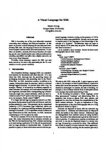
3. The SEAMAN System Architecture and the Software Development Process The architecture of the system SEAMAN is given in figure 1. The system consists of two main modules, namely the Software Development Environment Generator (SDEG for short) and the Visual Programming Environmnt (VPE for short), both of which interact with a repository. The SDEG is primarily used for customizing the software development environment (VPE) and the process, and for upgrading the repository. The VPE module is a visual programming environment generated by the SDEG; it allows to visually build software systems according to the methods specified through the SDEG, also using pre-defined software templates from the repository. In VPE it is also possible to standardize procedures and to store them in the repository for future reuse.
SDEG
Notation Editor
Symbols
Syntax Editor
Grammar
VPE Generator R E P O S I T O R Y
KB Editor KB
VPE
Visual Editor
Visual Software Specs
REPOSITORY
M A N A G E R
Inference Module
Parser
Source Code
Figure 1. The SEAMAN system The module SDEG allows to customize the methodology notations through the Notation Editor, and to specify their syntactic properties through the Syntax Editor. Moreover, SDEG is also used to specify rules and properties of the methodology, and their behaviour inside the software development process being defined. This task is accomplished by the Knowledge Base Editor (KB Editor, for short), which is provided with visual operators to directly specify the semantics of the models [6]. The VPE uses visual language generation techniques [4] to construct the target visual programming environment. The VPE module includes a visual editor which allows to visually build application programs, and visual software templates to be stored in the repository. The objects that can be manipulated at this level depend upon the methods defined in SDEG. Sample visual languages that can be defined in SDEG include flow-charts, object diagrams, entityrelationship diagrams, other than user-defined diagrams etc. The programmer uses the defined visual languages to build his schemes and can combine them with pre-built visual or textual software templates
from the repository. A parser will compile these software specifications into source code by also using an inference module which enforces the semantics of the models defined in SDEG. The definition, generation and use of a software development environment with SEAMAN involves the three professional profiles mentioned above, as specified in the following. The System Engineer 1. uses SDEG to define, build and/or upgrade the software development environments (VPEs); 2. uses the generated VPE to define initial templates to be stored in the repository. The Project Administrator 1. defines the project standards; 2. selects the appropriate templates from the repository, customizes them to the project standards and stores them back to the repository. 3. periodically gives feedback to the System Engineer for upgrading the VPE and the system templates.
The developer 1. Builds application programs using the visual language provided by the VPE with the possibility of including templates from the repository. The templates might require customization, which entails selecting them from the repository, tailor them to the program under development and possibly store them back to the repository. 2. periodically gives feedback to the System Engineer and the Project Administrator for upgrading the VPE, the system and the project templates.
4. Case Study. The prototype tool SDEG is being built on the top of the Visual Language Compiler-Compiler [4]. This tool (named VLCC for short) allows the automatic construction of a visual programming environment once the visual language to be hosted has been specified in its structural and visual components. In particular, VLCC presents a production editor for the definition of a positional grammar describing the syntax and the semantic routines for the visual language, and a symbol editor for the definition of the visual and logical aspects of its objects (tokens). These specifications are processed by VLCC and then by a C++ compiler to produce the final programming environment. The purpose of the system SEAMAN is to provide support in building software engineering environments suited to a particular working environment. We have experimented it to improve the development of business oriented applications for financial environments, government agencies, telecommunication companies, etc.; the target language of the case study is COBOL. The enhancement of the software development process in these environments presented several problems. The adoption of CASE tools would entail big investments without a clear understanding of the real advantages in the short term, leading to the problems mentioned above. While waiting for the right CASE system, many companies have devised their own partial solutions for improving their development process. Sometimes they choose to produce high level specifications of their systems, using front-end CASE .tools, but they do not always maintain the implemented system consistent with these high level
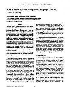
specifications. Other observed ad hoc solutions try to remove repetitive programming work. For instance, in our target environment developers used to pre-build pieces of source code that would have to be retyped every time a batch or tele-processing transaction was to be built. Our goal has been to generalize this practice, by providing a tool supporting the construction of pre-built pieces of a system, not only at source code level, but also at design and analysis level. In this case-study we have used SEAMAN to customize a flow-chart based visual language for the specification of a general model of teleprocessing transactions. The model is stored in a repository and can be instantiated when needed. Some modules of the transaction can be parameterized and need to be specified by the developer, but this applies only to a small percentage of the whole transaction. We show the amount of programming work that has been avoided with this method, which can be generalized to higher level specifications. To do this, we used SDEG to create a VPE implementing a particular type of flowcharts. This visual language allows the definition of semi-structured Control Flow Diagrams (CFD for short) where nodes can be terminals or non terminals. In this last case, nodes can be associated to nested CFDs, to code, or to references to code blocks in the repository. Depending on the user profile, CFDs can be defined for each type of application at different levels of abstraction: the lowest level is a specific control flow diagram where all the nodes are associated to the code implementing that node, or to a reference; at the project level, the CFD presents nodes which have been instantiated for a particular project and nodes left uninstantiated; at the highest level, the system level, the CFD only describes the basic characteristics of a generic application of a certain type (batch, teleprocessing, etc.). The two screen dumps in Figure 2(a) and 2(b) show two control flow diagrams. The first one represents the standard schema of a generic teleprocessing application. It is produced by the System Engineer. The second represents a customization of the previous one to a particular project and to a particular application: the development of a transaction menu. It can be noted that the layout is slightly different from the previous one.
(a)
(b) Figure 2. Two Control Flow Diagrams The text window shows the association between each intended menu item and the corresponding program. The gray boxes need to be filled by the programmer. In this single case study, the Knowledge Base is encapsulated in the semantic routines associated to the grammar rules specifying the syntax of the semistructured flowchart visual language. These semantic routines translate the software specifications provided by a programmer in the corresponding COBOL source code. The piece of COBOL source code given below is generated by compiling the CFD in Figure 2(b).
CHECK-MENU-ITEM SECTION CHECK-MENU-ITEM-BEGIN MOVE LOW-VALUE TO H-NEXT-TPR PERFORM INIT-MAP-FIELD- COMMAREA MOVE MCHOICEI TO CA-S-CHOICE IF MCHOICEI = ‘ICA ‘ OR ‘ ICA’ MOVE ‘ICA ‘ TO MCHOICEI PERFORM CHK-INPUT-DATA-ICA MOVE ‘GHT0210’ TO H-NEXT-TPR ELSE
* * * * * * * * * * * * * * * * * * ELSE MOVE ‘VAS ‘ TO MCHOICEI PERFORM CHK-INPUT-DATA-VAS MOVE ‘GHT0260’ TO H-NEXT-TPR ELSE * * * * * * * * * * * * * * * * * * CHECK-MENU-ITEM-EXIT EXIT However, the following code for checking input data for each choice must be explicitly typed in by the developer. In the current prototype this can be done by clicking on the block check input data after having selected the TEXT button. ** **-- check the input data for the **-- choice ICA ** CHK-INPUT-DATA-ICA SECTION 00. **-- code lines to check the **-- correctness of input data **-- corresponding to the choice ICA 99. EXIT
need to further investigate these topics, in order to find efficient ways to v i s u a l i z e and c l a s s i f y information from lower level constructs into higher level visual constructs to support software reuse.
References [1] David Sharon, and Rodney Bell, “Creating Integrated Environments”, IEEE Software, vol. 12 n.2, March 1995, pp. 76-85. [2] Brooks F., “No Silver Bullet: Essence and Accidents of Software Engineering”, IEEE Computer, vol. 20 n.4, April 1987. [3] Henry David Crockett, “What’s the proper role for CASE Tools”, IEEE Software, vol. 12 n.2, March 1995, pp. 19-20. [4] Costagliola G., De Lucia A., Orefice S., Tortora G., “Automatic Generation of Visual Programming Environments”, IEEE Computer, n. 28, pp. 56-66 1995. [5] Coad P., Yourdon E., “Object Oriented Analysis”, Prentice Hall 1991. [6] S.K. Chang, G. Polese, S. Orefice, M. Tucci, "A Methodology and Interactive Environment for Iconic Language Design", International Journal of Human Computer Interaction, Vol. 41, 1994, pp. 683-716. [7] Fisher A. S., “CASE: Using Software Development Tools”, Wiley and Sons 1988.
5. Further Developments. In this work we have used visual language technology for managing the software development process. Further research includes the application of the approach to more complex software development environments. We have introduced the most common graphical notations in our system, including Object Oriented Analysis and Design notations, and the checking activities they prescribe. We are seeking methods and interfaces to make the customization process more general and user friendly. Besides, we would like to visually specify the traceability properties across different models and to automatically store this information in a knowledge base. We have already started working on the automatical translation between textual programs and visual programs. We
[8] McClure Carma, “CASE is Software Automation”, Prentice Hall 1989.