frameworks in which to construct and maintain software. Visual ... this thesis. Object-oriented concepts and development are discussed, along with some.
A Visual Programming Environment for ObjectOriented Languages
John Collis Grundy
A thesis submitted in fulfilment of the requirements for the degree of Master of Science in Computer Science University of Auckland
February 1991
Abstract
Visual programming environments provide more integrated, high-level, user friendly frameworks in which to construct and maintain software. Visual programming is particularly appropriate to object-oriented languages, due to the inherently visual nature of their structure. The concepts of visual programming and current research in this area are summarised in this thesis. Object-oriented concepts and development are discussed, along with some representative object-oriented languages. Ispel, a visual programming environment for object-oriented languages, is developed and described. Ispel allows programmers to graphically represent and manipulate the high-level, object-oriented aspects of programs. Two prototypes of Ispel have been implemented. The first was implemented in Prolog, and was used to refine the user interface and visual programming facilities of the environment. Evaluation and enhancement of this prototype has determined the value of visual programming for object-oriented languages. The second prototype was implemented in Eiffel, an object-oriented language, and assisted the development of an object-oriented implementation model for Ispel. The second prototype also assisted the development of a formal definition of Ispel. This is a concise, high-level notation for describing the behaviour of Ispel, and provides a formal framework for integrating future extensions. Possible enhancements to Ispel are described which would improve the visual programming environment it provides. The abstraction of aspects of Ispel to provide an environment for other languages, and for use in other applications, is also discussed.
Page i
Page ii
Contents Abstract..........................................................................................................................i Contents ...................................................................................................................... iii Chapter 1 ......................................................................................................................1 Introduction..................................................................................................................1 1.1
Rationale for Research ...............................................................................................1
1.1.1
Using Visual Techniques in Computing ...............................................................1
1.1.2
Object-Oriented Languages...................................................................................2
1.1.3
Improving Programming Environments................................................................2
1.2
Outline of Thesis .........................................................................................................3
Chapter 2 ......................................................................................................................5 Visual Programming Environments ..........................................................................5 2.1
Programming Environments .....................................................................................5
2.2
Visual Programming Environments .........................................................................7
2.3
Advantages of Visual Programming .........................................................................8
2.3.1
User Interface ........................................................................................................8
2.3.2
Visualisation of Programs .....................................................................................8
2.3.3
Program Navigation ..............................................................................................9
2.3.4
Integration of Tools ...............................................................................................9
2.4
Taxonomy of Programming Environments............................................................10
2.4.1
Conventional Environments ................................................................................10
2.4.2
Integrated Environments and Browsers...............................................................11
2.4.3
Visual Programming Environments ....................................................................15
2.4.4
Program Visualisation .........................................................................................17
2.4.5
Example-Based Programming.............................................................................19
2.4.6
Computer-Aided Software Engineering ..............................................................20
2.4.7
Other Visual Modelling Systems ........................................................................23
2.5
Summary....................................................................................................................23
Chapter 3 ....................................................................................................................25 Visual Programming for Object-Oriented Languages...........................................25 3.1
Object-Oriented Programming Concepts ..............................................................25
Page iii
3.1.1
Object-Oriented Design.......................................................................................25
3.1.2
Objects and Classes .............................................................................................26
3.1.3
Type Aggregation................................................................................................26
3.1.4
Genericity ............................................................................................................27
3.1.5
Generalisation......................................................................................................27
3.1.6
Classification .......................................................................................................28
3.2
Object-Oriented Development.................................................................................28
3.2.1
Software Development Life-cycle.......................................................................29
3.2.2
Identifying Objects and Classes ..........................................................................29
3.2.3
Class Interface Design.........................................................................................30
3.2.4
Inheritance Hierarchies........................................................................................30
3.2.5
Implementing Classes..........................................................................................31
3.3
Class Language and Eiffel........................................................................................31
3.3.1
Class Language....................................................................................................31
3.3.2
Eiffel ....................................................................................................................32
3.3.3
Development Environments ................................................................................32
3.4
Other Object-Oriented Languages..........................................................................34
3.5
Class Structure Diagrams ........................................................................................35
3.6
The Ispel Visual Programming Environment ........................................................37
3.6.1
Current Use of Class Structure Diagrams ...........................................................37
3.6.2
Construction of Class Structure Diagrams ..........................................................37
3.6.3
Visual Programming Using Class Structure Diagrams .......................................38
3.6.4
Ispel .....................................................................................................................38
3.7
The Basic Concepts of Ispel .....................................................................................38
3.7.1
Overview of Ispel ................................................................................................38
3.7.2
Programs as an Underlying Representation ........................................................39
3.7.3
Multiple Views of the Underlying Representation..............................................40
3.7.4
Elements of Views...............................................................................................42
3.7.5
User Interface ......................................................................................................43
3.7.6
Well Integrated Tools ..........................................................................................44
3.8
Summary....................................................................................................................45
Chapter 4 ....................................................................................................................47 The Prolog Prototype.................................................................................................47 4.1
A Prolog Prototype for User Interface Aspects......................................................47
4.2
The Development Process ........................................................................................47
4.2.1
Specification and Design.....................................................................................48
4.2.2
Rapid Prototyping................................................................................................48
4.2.3
The Implementation Language............................................................................49
Contents
Page iv
4.3
User Interface............................................................................................................50
4.3.1
Visual Representation of a Program....................................................................50
4.3.2
User Input and Output .........................................................................................52
4.3.3
Applications, Views, and Windows ....................................................................54
4.3.4
Textual Views of Classes ....................................................................................59
4.3.5
Visual Manipulation Using Tools .......................................................................60
4.3.6
Class and Feature Names ....................................................................................64
4.3.7
Saving and Restoring Applications .....................................................................64
4.4
Implementation .........................................................................................................65
4.4.1
Structure of the Prolog Prototype ........................................................................65
4.4.2
Relational Model .................................................................................................66
4.5
Summary....................................................................................................................69
Chapter 5 ....................................................................................................................71 Evaluation and Enhancement of the Prolog Prototype ..........................................71 5.1
Evaluation..................................................................................................................71
5.1.1
Some Applications for the Prolog Prototype.......................................................71
5.1.2
Program Efficiency..............................................................................................72
5.1.3
Performance as a Visual Programming Environment .........................................72
5.2
Some User Interface Deficiencies ............................................................................73
5.2.1
Visual Manipulation ............................................................................................74
5.2.2
Constraint of Class Language Program Construction .........................................74
5.2.3
Visual Representation..........................................................................................75
5.2.4
Navigation ...........................................................................................................76
5.2.5
Renaming Classes and Features ..........................................................................76
5.2.6
Underlying Representation..................................................................................76
5.2.7
Lack of a Parser and Run Time System ..............................................................77
5.2.8
Location and Documentation of Existing Classes...............................................77
5.3
Evaluation of the Relational Model.........................................................................78
5.3.1
Advantages of the Relational Model ...................................................................78
5.3.2
Deficiencies of the Relational Model ..................................................................78
5.4
Enhancements ...........................................................................................................79
5.4.1
Line and Box Addition ........................................................................................79
5.4.2
Cutting of Boxes and Lines .................................................................................80
5.4.3
Parameters, Procedures, and Functions ...............................................................80
5.4.4
Visual Layout ......................................................................................................83
5.4.5
Expansion of Class Features and Generalisations ...............................................85
5.4.6
Views and Windows............................................................................................87
5.4.7
Renaming and Re-selecting Classes and Features...............................................87
Contents
Page v
5.4.8
Consistency with Underlying Representation .....................................................88
5.4.9
Standard Classes..................................................................................................88
5.5
Some Visual Programming Techniques..................................................................88
5.5.1
Multiple Views of a Program ..............................................................................88
5.5.2
Multiple Windows ...............................................................................................93
5.5.3
Graphical and Textual Representations...............................................................93
5.6
Summary....................................................................................................................93
Chapter 6 ....................................................................................................................97 The Eiffel Prototype...................................................................................................97 6.1
The Eiffel Prototype..................................................................................................97
6.1.1
Rationale for the Eiffel Prototype .......................................................................97
6.1.2
The Development Process ...................................................................................98
6.1.3
The Object-Oriented Approach ...........................................................................98
6.2
User Interface..........................................................................................................100
6.2.1
Appearance ........................................................................................................100
6.2.2
Views.................................................................................................................101
6.2.3
User Input and Output .......................................................................................102
6.2.4
Different Facilities from the Prolog prototype ..................................................102
6.3
Implementation .......................................................................................................103
6.3.1
Framework.........................................................................................................103
6.3.2
Objects...............................................................................................................106
6.3.3
Operations .........................................................................................................111
6.3.4
Relationships .....................................................................................................113
6.4
Evaluation................................................................................................................118
6.4.1
Performance as a Visual Programming Environment .......................................118
6.4.2
Implementation..................................................................................................118
6.4.3
Further Development of the Eiffel Prototype....................................................120
6.5
Object-Oriented Development...............................................................................120
6.5.1
Suitability of an Object-Oriented Language to Implement Ispel ......................121
6.5.2
Eiffel and its Environment ................................................................................121
6.5.3
Some Facilities for a Visual Programming Environment .................................122
6.5.4
Some Techniques Developed During Implementation......................................122
6.6
Summary..................................................................................................................124
Chapter 7 ..................................................................................................................127 A Formal Definition of Ispel ...................................................................................127 7.1
The Need for a Formal Definition .........................................................................127
7.2
Predicate Calculus and Weakest Preconditions...................................................128
Contents
Page vi
7.3
Notation....................................................................................................................128
7.4
Structure of the Formal Definition........................................................................129
7.4.1
Object-Oriented Program ..................................................................................130
7.4.2
Underlying Representation................................................................................131
7.4.3
Visual Representation........................................................................................132
7.5
Mappings .................................................................................................................133
7.5.1
Visual Representation to Screen Representation Mapping ...............................133
7.5.2
Visual Representation to Underlying Representation .......................................134
7.5.3
Underlying Representation to Object-Oriented Program Mapping...................135
7.6
Operations ...............................................................................................................136
7.6.1
Add a Class Box and Node................................................................................137
7.6.2
Add a Generalisation Line and Arc ...................................................................138
7.6.3
Add a Feature Box and Arc ...............................................................................138
7.6.4
Hide a Box.........................................................................................................139
7.6.5
Cut a Class Box .................................................................................................140
7.6.6
Rename a Class .................................................................................................141
7.6.7
Produce an Object-Oriented Program Graph ....................................................141
7.7
Extensions to the Formalism..................................................................................142
7.8
Summary..................................................................................................................143
Chapter 8 ..................................................................................................................145 Conclusions...............................................................................................................145 8.1
Research Contributions..........................................................................................145
8.2
Programming Environments .................................................................................146
8.2.1
Suitability of Programming Environments to Languages .................................146
8.2.2
Integration and Appropriate Tools ....................................................................146
8.2.3
Performance.......................................................................................................147
8.3
Visual Programming Environments .....................................................................147
8.4
The Ispel Visual Programming Environment ......................................................148
8.4.1
The Prototypes of Ispel......................................................................................148
8.4.2
User Interface Issues..........................................................................................148
8.4.3
Visual Programming Issues...............................................................................149
8.4.4
Implementation Issues .......................................................................................149
8.4.5
Formal Specification .........................................................................................150
8.4.6
Defining Visual Aspects....................................................................................150
8.5
Program Development............................................................................................150
8.7
Prolog Programming ..............................................................................................153
8.8
Object-Oriented Programming .............................................................................153
8.9
Summary..................................................................................................................154
Contents
Page vii
Chapter 9 ..................................................................................................................157 Future Research .......................................................................................................157 9.1
Enhancement of Ispel Visual Programming ........................................................157
9.1.1
Improvements to Existing Facilities..................................................................157
9.1.2
Increase Visual Programming Power ................................................................161
9.1.3
Cut, Copy, Paste, and Undo ..............................................................................163
9.1.4
Parser for Graphics ............................................................................................163
9.2
Ispel Development Environment Tools.................................................................163
9.2.1
Compiler and Run-Time System .......................................................................164
9.2.2
Class Library System.........................................................................................164
9.2.3
Class Abstracter and Documentation Tool........................................................164
9.2.4
Class Location Facility ......................................................................................165
9.2.5
Hierarchy Flattener............................................................................................165
9.2.6
CASE Tools for Design, Analysis, and Documentation ...................................165
9.2.7
Formal Specification Tool.................................................................................166
9.2.8
Structure-Oriented Editor ..................................................................................166
9.2.9
User Interface Construction Tool ......................................................................167
9.3
Extension to a Multi-user Environment ...............................................................167
9.4
Enhancement of the Implementation Model ........................................................167
9.5
Enhancement of the Formal Specification............................................................168
9.6
Performance Analysis and Evaluation of Ispel ....................................................169
9.7
Generalisation of Ispel to Other Languages.........................................................169
9.8
Abstraction of Ispel to Visual Modelling ..............................................................170
9.8.1
Entity-Relationship Modelling ..........................................................................171
9.8.2
CASE Methodologies........................................................................................171
9.8.3
Document Processing ........................................................................................171
9.8.4
General Graph, List, and Tree Manipulation.....................................................171
9.8.5
Cataloguing .......................................................................................................171
9.8.6
Dynamic Object Modelling ...............................................................................172
9.9
Describing Visual State Change ............................................................................172
9.10
A General Model and Modeller Generator ........................................................173
9.11
Summary................................................................................................................174
Appendix A ...............................................................................................................177 Specification of the Prolog Prototype.....................................................................177 A.1
Prolog Prototype Basic Characteristics ...............................................................177
A.2
Application Layout ................................................................................................179
A.3
Multiple Views........................................................................................................180
Contents
Page viii
A.4
Representation of Classes and Class Relationships ............................................182
A.5
Manipulating Class Diagrams ..............................................................................183
A.5.1
Selecting Operations to Perform ......................................................................183
A.5.2
Adding Classes to the Current View ................................................................184
A.5.3
Connecting Classes in the Current View..........................................................185
A.5.4
Manipulating Classes in the Current View.......................................................187
A.5.5
Display and Editing of Feature Names for Classes ..........................................187
A.5.6
Selection Manipulation in the Current View and Between Views..................188
A.5.7
Expansion and Contraction of Views ...............................................................188
A.5.8
Other Class Relationships and Views...............................................................189
A.6
Editing Class Details as Text.................................................................................189
Appendix B ...............................................................................................................195 Prolog Prototype Implementation ..........................................................................195 B.1
The Prototype Structure........................................................................................195
B.2
The Relational Model.............................................................................................197
B.3
Database Access Predicates and Examples..........................................................199
B.4
Prototype Save Files...............................................................................................202
Appendix C ...............................................................................................................205 Weakest Precondition Notation ..............................................................................205 C.1
Weakest Precondition Notation ............................................................................205
C.2
Assignment..............................................................................................................206
C.3
Conditional Statement ...........................................................................................206
C.4
Iteration ..................................................................................................................206
C.5
Execute ....................................................................................................................207
C.6
Operation Parameters ...........................................................................................208
C.7
Undo ........................................................................................................................209
C.8
Complex Operations ..............................................................................................209
Appendix D ...............................................................................................................213 Ispel Formal Definition............................................................................................213 D.1
Abbreviations .........................................................................................................213
D.2
Addition Operations ..............................................................................................214
D.2.1
Add a Class Box ...............................................................................................214
D.2.2
Add a Feature Box and Line.............................................................................214
D.2.3
Add a Specialization Box and Line ..................................................................214
D.3
Removal Operations ..............................................................................................214
D.3.1
Contents
Cutting an Inheritance Line ..............................................................................214
Page ix
D.3.2
Hiding a Class Box ...........................................................................................215
D.3.3
Hiding a Feature Box........................................................................................215
D.3.4
Cutting a Class Box ..........................................................................................215
D.3.5
Cutting a Feature Box.......................................................................................215
D.4
Renaming Operations............................................................................................215
D.4.1
Renaming a Class .............................................................................................216
D.4.2
Renaming a Feature ..........................................................................................216
D.5
Other Operations ...................................................................................................216
D.5.1
Re-selecting a Class..........................................................................................216
D.5.2
Expanding a Class ............................................................................................217
D.6
Future Extensions ..................................................................................................218
Contents
Page x
Chapter 1 Introduction Object-oriented programming has gained popularity in computing (Booch, 85, Coad and Yourdon, 91, and Meyer, 88). This research enhances object-oriented programming by improving the development environments for object-oriented languages. This is achieved by utilising visual programming techniques to represent and manipulate these programs. This chapter discusses the rationale for this research. Visual programming, object-oriented programming, and programming environments are introduced. The contributions of this research are summarised, and an outline of the structure of this thesis is presented.
1.1
Rationale for Research
Programming computers is a complex task, which becomes more difficult as programs and software systems get larger. To address this problem, new techniques to assist software construction are being developed (Henderson and Notkin, 87). Two important areas of research are programming languages and programming environments (Dart et al, 87). Two current technologies which are gaining popularity are object-oriented programming and visual programming. Most current object-oriented programming languages have poor programming environments which do not assist software development. In this research, object-oriented programming is assisted by using visual programming to provide an improved environment for these languages.
1.1.1
Using Visual Techniques in Computing
Human-computer interaction is very important (Fischer, 87). Instructing computers can be achieved in many ways. As technology advances, new methods of communication are being developed which enhance the human-computer interaction process. Interactive graphical user interfaces have become available with the widespread use of personal workstations (Ambler and Burnett, 89, Raeder, 85, and Wasserman and Pircher, 87). These provide a multidimensional visual interface between a human and computer software. Graphical interfaces allow users to interact with computers in a more natural and meaningful way. Direct manipulation interfaces, which provide a mouse device for pointing at objects and manipulating them, also help to make computers easier to use (Myers, 90). Graphical interfaces have the advantage that they can represent information and allow Chapter 1
Introduction
Page 1
information to be manipulated at higher levels of abstraction. This results in a more powerful interface for specifying commands and obtaining information than is provided by purely textual interfaces.
1.1.2
Object-Oriented Languages
Computers can be instructed using a large variety of programming languages. As programs grow larger, they become more difficult to construct, understand, and maintain. Conventional programming languages, such as Pascal or C, are structured around procedural and functional components of software systems. These are the aspects of software that are most prone to change (Meyer, 88), and often the most difficult to conceptualise. Object-oriented programming allows programmers to structure programs around data. Data, and the operations that operate on data, are encapsulated together. Real world and abstract objects are modelled in this way, and classes of these objects can be defined. A variety of inter-class relationships are present which assist in structuring programs, reusing information, and categorising objects. Object-oriented techniques and languages assist the design, construction, and maintenance of large software systems (Booch, 87, Coad and Yourdon, 91, and Meyer, 88). The two representative object-oriented languages used in this thesis are Class Language and Eiffel. Class Language was developed at the University of Auckland (Hamer, 90), and Eiffel was developed at Interactive Software Engineering (Meyer, 88). These languages and their environments are described in more detail in Section 3.3.
1.1.3
Improving Programming Environments
Most of the existing programming environments for object-oriented languages only give limited assistance to programming in this paradigm. To exploit its advantages, programmers require good environments and tools to assist them. The programming environments for object-oriented languages are enhanced in this research by using visual techniques. The current environments for both Class Language and Eiffel are deficient in many ways. This research designs and prototypes Ispel, a visual programming environment for these languages. The high-level aspects of object-oriented languages can be represented well using graphical techniques (Wasserman et al, 90, and Wilson, 90). By constructing these aspects in a visual programming environment, the design and implementation processes can be enhanced. Other programming environments, such as those for conventional languages, can also be enhanced using visual programming.
Chapter 1
Introduction
Page 2
There is a growing interest in research in this area. Many visual programming systems have been developed which exploit similar ideas to those presented in this thesis. These include PECAN (Reiss, 85), Graspin (Mannucci et al, 89), TANGO (Stasko, 89), and others (Ambler and Burnett, 89, Myers, 90, and Raeder, 85).
1.2
Outline of Thesis
The following chapters are organised thus: • Chapter 2 defines visual programming and programming environments. A taxonomy of programming environments is presented which forms a survey of research in this area. • Chapter 3 introduces object-oriented language concepts and object-oriented development techniques. Class Language and Eiffel are described. The concepts of the Ispel visual programming environment are presented. • Chapter 4 describes a Prolog prototype of Ispel. This provides a visual programming environment for Class Language. The user interface, visual programming facilities, and implementation of this prototype are discussed. • Chapter 5 evaluates this Prolog prototype, describes its advantages and deficiencies, and presents some enhancements to it. Some visual programming techniques developed using Ispel are also discussed. • Chapter 6 describes an Eiffel prototype of Ispel, which was used to refine an implementation model. Object-oriented development of this prototype, using Eiffel, is discussed. • Chapter 7 presents a formal definition of Ispel. • Chapter 8 draws conclusions from this research. • Chapter 9 discusses some future extensions of Ispel. It also presents some future directions for research.
Chapter 1
Introduction
Page 3
Chapter 1
Introduction
Page 4
Chapter 2 Visual Programming Environments The concepts of programming environments and visual programming environments are introduced in this chapter. The advantages of visual programming techniques over conventional, textual ones are discussed. A taxonomy of visual programming environments is presented, which is illustrated with examples of representative languages and systems. This taxonomy forms a survey of the current research on visual programming and visual programming environments.
2.1
Programming Environments “Computer scientists have created numerous development tools for other disciplines, such as computer-aided design and computer-aided manufacturing. Only relatively recently, however, has the need for computer scientists to aid themselves been recognised.” (Henderson and Notkin, 87)
Programming environments are software and hardware tools which a system developer uses to build software systems (Dart et al, 87). When developing programs, a programmer works within an environment which facilitates the programming task. Programming environments provide tools which allow a programmer to edit, compile, and execute programs. They also provide additional facilities to assist this development process. Dart et al (87) make a distinction between programming environments and software development environments. • Programming environments support only the coding phase of the software development cycle. For example, programming in the small1 tasks such as editing and compiling.
1“Programming
in the small” refers to single programmer tasks accomplished on one machine. For example, editing and compiling a program are single programmer tasks, but there may be several programmers working on the same software system. Chapter 2
Visual Programming Environments
Page 5
• Software development environments augment or automate all the activities comprising the software development cycle. This includes programming in the large2 tasks such as project and team management, and long term maintenance of software. The focus of this thesis are programming environment issues. However, some software development environment aspects are discussed. Dart et al (87) and Henderson and Notkin (87) give a taxonomy of programming environments. This can be used to classify programming environments and to understand the technological trends that have produced existing environments (Dart et al, 87): • Language-centred environments. These are built around one language and provide a programming tool suitable for that language. These environments are highly interactive and focus on a narrow set of software development activities. Examples include InterLISP, Smalltalk, and Cedar (Dart et al, 87), Trellis/Owl (O’Brien et al, 87), THINK Pascal (Symantec, 89), and LPA MacProlog (LPA, 89a). • Structure-oriented environments. These environments focus on the manipulation of structures rather than programs. The notion of structure editing produced structure-oriented editors and the notion of environment generators. Examples include the Cornell Program Synthesizer (Reps and Teitelbaum, 87), and the PECAN system (Reiss, 85). • Toolkit environments. These are loosely interrelated collections of tools for “programming in the large” tasks. The environment does not constrain the use of these tools in any way. For example, Arcadia (Dart et al, 87), and Gandalf (Henderson and Notkin, 87), are generators for toolkit environments. • Method-based environments. These environments provide tools for a broad range of software development activities. They also include tools for particular specification and design methods. Examples include Software through Pictures (Wasserman and Pircher, 87), Graspin (Mannucci et al, 89), and a variety of CASE tools (Dart et al, 87). The majority of the programming environments discussed in this chapter are languagecentred environments. The Ispel visual programming environment presented in Section
2“Programming
in the large” refers to multiple programmer tasks accomplished over several networked or distributed machines. For example, the management and coordination of many programmers working on different aspects of a single system. Chapter 2
Visual Programming Environments
Page 6
3.5 is a language-centred environment with some structure-oriented and method-based design aspects.
2.2
Visual Programming Environments “With the availability of graphic workstations has come the increasing influence of visual technology on language environments.” (Ambler and Burnett, 89)
New graphics workstations and their wide availability means powerful graphics facilities are now available to programmers (Ambler and Burnett, 90, Myers, 90, and Raeder, 85). The graphical facilities provided by these workstations can be utilised to assist the software development process. The use of graphics to construct or view programs is called visual programming. Environments that utilise an aspect or aspects of visual programming are called visual programming environments. Visual programming environments use graphical techniques for all, or part, of program construction and visualisation. They allow a programmer to specify a program in a two (or more) dimensional fashion, whereas conventional textual languages are only one dimensional (Myers, 90). Some two-dimensional visual aspects are utilised for textual programming, such as indentation. However, textual programming usually lacks the high-level abstraction that visual programming can provide. Programs such as MacDraw are not visual programming environments as they do not create programs (Myers, 90). Ideas related to visual programming include program visualisation and example-based programming. In program visualisation, a program is specified in a conventional, textual manner. Graphics are used to illustrate aspects of the program or its run time execution. Myers (90) makes a clear distinction between visual programming systems and program visualisation systems. Program visualisation systems can be classified into data visualisation and code visualisation systems, depending on the aspect of a program they model. Data visualisation can also be classified into static and dynamic modelling systems. Static program visualisation can only take snapshots of a running program, but dynamic systems can model changing program data. Abstract visualisation, or algorithm animation, models an algorithm as it is executed, instead of, or in addition to, its code and data. Example-based programming allows a programmer to specify examples of input and output during the programming process. There are two types of example-based programming systems, called programming by example and programming with example. Programming by example uses examples to try and infer a program which can construct them. Programming with example requires the programmer to specify everything about a program, and nothing is inferred. Test data and results are given to example-based Chapter 2
Visual Programming Environments
Page 7
programming systems before execution, rather than comparing output with expected values, as with conventional programming. A visual programming environment can be defined as utilising some form of visual programming. In addition, this visual construction of programs can be augmented with a program visualisation or example-based programming component.
2.3
Advantages of Visual Programming
It is desirable for programming environments to provide several facilities to assist a programmer during program development. These include: a good user interface, a clear representation of programs, versatile program navigation, and a variety of integrated tools. Visual programming environments can assist in providing these facilities in a better form than conventional environments (Raeder, 85).
2.3.1
User Interface
The user interface presented to programmers is improved by using visual techniques. Conventional interfaces are difficult to learn and use (Myers, 90, and Raeder, 85). They often do not provide a clean and concise method of specifying actions and obtaining information. Visual interfaces provide an interface which is more natural, more flexible, and easier to use, as they utilise both graphics and text. This allows for a more expressive description of commands, and a more powerful and user-friendly method for presenting and manipulating information (Myers, 90, and Raeder, 85). The direct manipulation interface has become popular and visual programming helps to utilise this technology to its fullest (Myers, 90). Elements of visual programs can be pointed to and operated on. This gives the programmer the impression that they are directly constructing a program. They are no longer abstractly designing a program, but constructing it from visual base elements. The provision of a consistent user interface with the same behaviour in different aspects of program development, contributes to the seamless integration of an environment. A visual interface is easier to keep uniform than a textual one. Different parts of a software development environment can utilise a similar interface with the same look and feel aspects. This assists the software development process (Raeder, 85, and Wasserman and Pircher, 87).
2.3.2
Visualisation of Programs
A graphical user interface shows more of a computer’s internal state, and is a more expressive medium of communication (Raeder, 85). The transfer rate of information is improved by using graphics where it is more natural to describe something visually than Chapter 2
Visual Programming Environments
Page 8
with text. The human visual system is designed to process multidimensional data. However, conventional languages and programming environments only provide a single dimensional textual form. Two-dimensional pictorial displays for data structures are very helpful, although little research has been done on programming using a visual representation of data structures (Myers, 90, and Raeder, 85). Visual programming allows the structure of programs, the flow of information, and the data structures that comprise the program, to be modelled. An environment utilising graphical program representations allows a programmer to process data in a format closer to the way objects are manipulated in the real world (Myers, 90). Graphics often provide a higher level description of information, and provide a higher level of abstraction (Myers, 90, and Raeder, 85). Issues such as syntax, or some semantic constraints, can be factored out of the programming process. This can result in improved productivity in program development. Often, graphical representation is a more appropriate and meaningful way of presenting information. For example, data is described and manipulated well using visual techniques.
2.3.3
Program Navigation
Navigation throughout a program during its development is based around the structure of the program (Fischer, 87, and O’Brien, 87). Many conventional programming environments provide little or no assistance to the programmer in moving between different parts of a program. Often, programmers want to focus on one aspect of a program during development, then move to a more or less abstract context, or a related context. Visual programming can utilise the visual representation of a program to provide a meaningful and flexible method of moving between different contexts (Ambler and Burnett, 90).
2.3.4
Integration of Tools
A program development environment consists of a variety of tools which are utilised during program construction and refinement. Examples include an editor, compiler, runtime system, project database, cross referencer, and documentation facility. These tools must be integrated in both their look and feel aspects (user interface), and their communication and data storage (underlying representations). Many conventional environments consist of quite distinct tools with very few common user interfaces and representational formats. Often, some tools are completely distinct from the rest of the environment, and the information provided by them is utilised only as the programmer sees fit. Examples are the increasingly popular CASE tools, which are
Chapter 2
Visual Programming Environments
Page 9
usually visual tools used for the design and analysis processes. However, information from them is stored in a format that can not be utilised by other tools in the environment, such as the editor and compiler. Visual programming environments have a common user interface between the different aspects of the environment, and the tools are often tightly integrated. For example, the Trellis/Owl environment provides a standard interface between tools for both user interaction and tool communication (O’Brien et al, 87). Most visual programming environments provide a good framework for integrating the user interfaces of tools. However, many existing environments require improved tool communication and data integration (Myers, 90).
2.4
Taxonomy of Programming Environments
This section presents a taxonomy of programming environments ranging from conventional text-based environments to integrated visual programming environments. Examples of representative environments and languages are given for each category. Several survey papers are available which provide definitions of visual programming and describe various systems. Some also compare and contrast different environments and evaluate their relative merits and deficiencies. Myers (90) and Raeder (85) provide a comprehensive survey of visual programming systems and describe visual programming and its advantages. Ambler and Burnett (90) and Dart et al (87) describe some representative visual programming environments and programming environments respectively. Other surveys are available in Ambler et al (88), Chang (87), and Henderson and Notkin (87).
2.4.1
Conventional Environments
Conventional programming environments utilise a textual representation for programs. Many are not well integrated and can be difficult to use (Myers, 90). The editor, compiler, and run-time system are usually quite distinct and have different user interfaces and data storage mechanisms. These environments do not provide many tools to assist program development. 2.4.1.1
Class Language and Eiffel
The environments for Class Language and Eiffel are both conventional in nature. Class Language programs are constructed and compiled as text, and then a run-time system is invoked to execute a program. Eiffel programs are also constructed in text and compiled. The compiled program can then be executed. The Eiffel environment provides a limited range of development tools and a program browser, although this is not particularly
Chapter 2
Visual Programming Environments
Page 10
useful. Neither environment is tailored to the particular needs of the languages being used. Both environments store programs as text files which can be accessed and modified by other utilities. However, this does not constitute integration, as there is no format to the text and the programs can be modified in an unconstrained way. The user interfaces of the editor and operating system are quite distinct. A programmer using the environment must move between different tools with different user interfaces and behaviour. Section 3.3 describes the environments for Class Language and Eiffel in detail. 2.4.1.2
Unix C and C++
The standard environments for C and C++ on Unix (Winblad et al, 90) are similar to those of Class Language and Eiffel. They are not integrated, are fully textual, and provide few tools to assist program development. Debugging tools are provided, but the range of program aspects they can describe is limited. No universal tools for structuring or visualising code at higher levels of abstraction exist. No navigation facilities based on program structure are available. 2.4.1.3
Other Conventional Environments
Other examples of languages with conventional environments include older versions of BASIC, Fortran, LISP, Pascal, and Prolog (Myers, 90). Many of these languages now have more integrated environments, which provide improved facilities for program development.
2.4.2
Integrated Environments and Browsers
Integrated environments that do not utilise visual programming techniques are the most common development environments (Myers, 90, and Winblad et al, 90). Some of these environments provide browsers which allow a programmer to view and navigate through programs. These browsers may show a visual representation of a program, but the diagrams can not be modified. Programs can not be constructed using visual programming techniques with these systems. Many of these environments are language-centred and tightly integrated. Most focus on programming in the small tasks, which are all completed within one application framework. The environment provided has a consistent user interface throughout, and many use a Macintosh-like desktop interface. Some environments are less tightly coupled, and have a tool approach. The environment is described as a set of integrated tools which have the same user interface and common
Chapter 2
Visual Programming Environments
Page 11
underlying representation. Extensibility is important in these environments. New tools can be added which can communicate and interface with existing tools in a consistent manner. Some environments allow existing tools to be tailored to the user by providing “preferences”, or a method of specifying operations to perform and how these operations are selected. 2.4.2.1
THINK Pascal
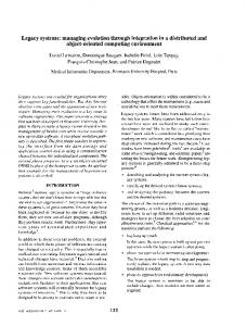
THINK Pascal on the Macintosh is a good example of a tightly-integrated, non-extensible, language-centred programming environment (Symantec, 89, and Winblad et al, 90). The environment supports programming in Object Pascal, and is a single Macintosh application. Editing, compiling, and executing programs take place within a single environment. All aspects of the environment use the Macintosh desktop metaphor, and thus have a consistent user interface. Programs can be debugged interactively, with the source code used for displaying the program statements being executed. Figure 2.1 shows an example screen dump from an application programmed in THINK Pascal. THINK Pascal also provides a browser for viewing object hierarchies. This allows for a limited form of program visualisation and navigation. Unfortunately, there are no facilities provided for visual programming, nor for viewing standard Pascal code visually. THINK Pascal can neither be interfaced to, nor included within, another environment framework. CASE tools used with THINK Pascal cannot use the programs stored by the THINK Pascal environment.
Chapter 2
Visual Programming Environments
Page 12
Figure 2.1 2.4.2.2
An example screen dump from THINK Pascal.
LPA MacProlog
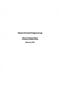
LPA MacProlog (LPA, 89a) is a version of Prolog for the Macintosh. The development environment for LPA MacProlog (LPA) is a tightly-integrated, extensible, languagecentred environment. Prolog programming is done within the one application, and all aspects of the environment have a consistent user interface. As with THINK Pascal, the desktop metaphor of the Macintosh is used. The LPA environment is extensible, as aspects of the environment can be changed. For example, a new menu option can be added to find and display Prolog predicates in a window, and the code to perform this new operation is written in Prolog. A graphical browser, which shows the Prolog call graph, is provided. Figure 2.2 shows an example screen dump from LPA. Development in the LPA environment is assisted by the incremental compilation of LPA. Prolog programs can be modified, and the changed parts re-compiled, while programs are running and being debugged. This greatly reduces the turn-around time between editing, compiling, and executing programs. The gap between these processes is reduced and almost merged within the LPA environment. Tools such as the window editor and the graphics libraries can be used in other Prolog applications. Like THINK Pascal, the
Chapter 2
Visual Programming Environments
Page 13
LPA environment can not be used for programming other languages, nor can it be interfaced to other tools outside the environment.
Figure 2.2 2.4.2.3
An example screen dump from LPA MacProlog.
Smalltalk-80
Smalltalk (Goldberg, 84, and Goldberg and Robson, 84) not only helped to popularise object-oriented programming, but also helped to introduce the desktop metaphor for user interfaces (Ambler and Burnett, 90). Smalltalk has a graphical user interface that has menus and windows for input and output with the programmer. In addition, the concept of program browsers is used. This allows a programmer to view selected portions of a program while the program is under construction, and during the maintenance of a program. However, graphics are not used to display elements of programs, and Smalltalk programs are displayed and manipulated in text. The Smalltalk environment is written in Smalltalk itself, and many aspects of the environment can be changed. This means that the Smalltalk environment is very extensible. The environment is not as tightly integrated as the LPA and THINK Pascal environments. Many aspects of the environment are programmed in Smalltalk and Chapter 2
Visual Programming Environments
Page 14
communicate via Smalltalk objects. These can be modified, and new tools and facilities can be added. 2.4.2.4
Trellis/Owl
The Trellis/Owl programming environment for the Trellis language (O’Brien, 87) is composed of several programming tools. These tools share a common form of user interface, and are not tightly coupled. These tools are integrated into an environment which is designed specifically for object-oriented programming in Trellis. New tools can be added to the environment, or existing tools modified, so long as they conform to both the user interface and the communication standards of the environment. Trellis provides a variety of tools such as an editor, compiler, debugger, cross referencer, and class library catalogue (O’Brien, 87). The browser provided uses only text to display class names, and does not use a visual representation. Programs can only be constructed and viewed in text. 2.4.2.5
Other Integrated Environments
Ambler et al (88) describe several programming environments ranging from integrated environments to visual programming systems. Other examples of integrated environments are: • ObjTalk (Fischer, 87) which provides an integrated environment and graphical program browser for an object-oriented language. • Cedar (Ambler and Burnett, 90, Ambler et al, 88, and Myers, 90) which is a complete programming system based around graphical representations. • Aloe (Ambler and Burnett, 90, and Ambler et al, 88) is a structure-oriented editor generator used in the Gandalf project. It can be integrated with external packages to form a programming environment. • InterLISP (Ambler et al, 88, and Winblad et al, 90) is a programming environment for a dialect of LISP which is tightly integrated and extensible. • Cornell Program Synthesizer (Ambler et al, 88, and Reps and Teitelbaum, 87) is a structure-oriented editor generator which can be used to generate environments. • Other Pascal and C systems, such as Objective-C (Winblad et al, 90), also have environments similar to the THINK Pascal environment.
2.4.3
Visual Programming Environments
Visual programming systems provide a method for constructing and viewing programs using graphical techniques. The environment provided is usually tightly-integrated and language-centred. By manipulating a visual representation of a program, the
Chapter 2
Visual Programming Environments
Page 15
programmer constructs the program using graphics rather than text. The graphical representation can also provide a basis for navigation throughout a program. Most visual programming systems are code or structure-oriented (Myers, 90, and Raeder, 85). Few systems use data-oriented program display, although Raeder (85) and Myers (90) point out that data structures often provide the most interesting forms to display graphically. In addition, data structures provide a good means of abstraction and structuring within a program (Myers, 90). As object-oriented programs are based on data structures, visual representation is suitable for them (see Section 3.6). Examples of visual programming systems are described in Ambler and Burnett (90), Ambler et al (88), Myers (90), and Raeder (85). 2.4.3.1
PECAN
The PECAN environment (Reiss, 85) provides a development environment for Pascal. The environment is tightly-integrated and language-centred, and has a common user interface throughout. The major contribution of PECAN was the notion of multiple views of program structures. A program can be viewed in PECAN in a variety of ways, and the program structure, semantics, and its execution, are displayed. The multiple views idea has been utilised by many systems (Ambler and Burnett, 90). Programs are represented as abstract syntax trees, and textual views are linked to this structure. When part of this structure is modified, all affected views are updated to reflect the change. Some graphical representations of programs are proposed which will allow the program dataflow and data structures to be displayed. In addition, views which can show the program execution, symbol table, and types, are proposed. The PECAN environment stores operations which are performed, and provides an undo facility to reverse operations. A list of operations is provided which can be edited and operations re-executed by the programmer. 2.4.3.2
Prograph
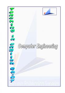
The Prograph system (Gunakara, 89) integrates object-oriented concepts with a dataflow language and an application builder. Prograph is visually programmed by constructing classes and methods. Methods are implemented using a dataflow language. The environment provided for Prograph is similar to the THINK Pascal environment in that it uses the Macintosh desktop metaphor. It is tightly-integrated and not extensible, although the method and class libraries provided can be extended by adding new methods and classes. Prograph has a consistent user interface and provides a range of facilities for building new user interfaces, including a sophisticated application builder. The objectoriented aspects of Prograph are not well developed, and the dataflow and objectChapter 2
Visual Programming Environments
Page 16
oriented aspects do not have a seamless integration. Figure 2.3 shows an example screen dump from the Prograph environment.
Figure 2.3 2.4.3.3
An example screen dump from Prograph.
Garden
Garden (Reiss, 87) is an automated design system used for prototyping new textual or visual languages and their environments. It is an abstraction of the ideas of PECAN (Reiss, 85) and is intended to be a general purpose environment generator for a variety of languages. Garden also supports multiple views, and allows a language to be defined and executed using a variety of views and construction techniques.
2.4.4
Program Visualisation
Program visualisation systems use graphics to represent some aspect of an executing program. Program visualisation may be combined with visual programming. There are three categories of program visualisation: code visualisation, data visualisation and abstract (or algorithm) visualisation. In addition, data visualisation may be static or dynamic. Chapter 2
Visual Programming Environments
Page 17
Program visualisation systems are described in Ambler et al (88), and Myers (90). 2.4.4.1
GraphTrace
GraphTrace (Kleyn and Gingrich, 88) allows object-oriented programs to be debugged using a visual representation of the run-time objects. These objects are viewed in a visual hierarchy, which can be traversed by the programmer. Programs are constructed using InterLISP in text. When running, they can be debugged using the GraphTrace object monitor. The programming environment used is the InterLISP environment, which is for programming using a dialect of LISP. The GraphTrace views are static visualisations, and are displayed when the user requests them. 2.4.4.2
PV
PV (Program Visualisation) is both a visual programming and program visualisation system (Myers, 90). Its intention is to assist programmers in forming a clear and correct image of a program’s structure and function (Brown et al, 85). PV allows a programmer to construct a program visualisation which can be viewed when the program is executed. Both static and dynamic diagrams are supported, and both textual and graphical diagrams are utilised. PV uses a form of multiple views and allows a programmer to move from one view to another during program execution. The PV environment is a collection of loosely coupled tools which are built around a project library where information is stored. These tools do not share a common user interface and the system is menu driven from one of its components. Further tools can be integrated into the environment, although this requires modification of the PV system (Brown et al, 85). 2.4.4.3
BALSA
BALSA (Myers, 90) is an algorithm animation system. It runs on a Macintosh and provides a tightly-integrated, language-specific environment. BALSA provides sophisticated views of programs during execution, and provides dynamic animation facilities. BALSA provides a library of existing views which can be utilised by a programmer to animate programs. However, if a new view is required, this must be constructed by programming using the Macintosh toolbox routines (Stasko, 89). BALSA can only be used to animate programs written in the BALSA programming language. 2.4.4.4
TANGO
TANGO (Stasko, 89) is an algorithm animation system. TANGO supports twodimensional animations on a graphics workstation. Programmers can produce real-time views of their programs using an algorithm animation design language or a direct Chapter 2
Visual Programming Environments
Page 18
manipulation animation design tool. TANGO animates a program during execution using a graphical representation of the algorithms of the program. TANGO is used to augment existing environments as a system for animating programs. TANGO can be integrated into other programming environments and is driven by a message-passing system. This loose system integration allows any program to be animated by generating events which drive the animation. 2.4.4.5
The Object-Oriented Diagramming System
The Object-Oriented Diagramming System (Myers, 90) allows a programmer to view objects at run-time and observe message-passing between objects. Objects are displayed as boxes, and arrows are drawn between boxes and elements of boxes. These show whether a method was handled by the object or a super-class of the object.
2.4.5
Example-Based Programming
Example-based programming uses examples of input and output to derive or specify programs. Examples are often provided using a graphical user interface, and programs constructed using graphical techniques. The environments provided by these systems are usually language-specific and tightly-integrated. Some example-based programming systems are described in Ambler et al (88), and Myers (90). 2.4.5.1
Rehearsal World Theatre
Rehearsal World Theatre (Ambler et al, 88) is a visual programming environment for non-programmers. The basic components of the environment are performers which interact with each other on a stage. The screen is a stage upon which performers (objects) perform actions they have been taught for a production (program). All the interactions with Rehearsal World Theatre are visual in nature. They consist of selecting a performer or sending a cue to a performer. Programming is undertaken by auditioning different performers by sending them cues and seeing how they respond. The cues and creation of performers are the examples the system receives and infers a program from. 2.4.5.2
Fabrik
Fabrik (Ingalls et al, 88) is a visual programming environment based on the dataflow programming paradigm. Fabrik programs are constructed by connecting low-level primitives together with wires, and thus building higher level program constructs. This is analogous to the Prograph dataflow component (Gunakara, 89). Fabrik allows the programmer to build user interface components, which are displayed on the screen and
Chapter 2
Visual Programming Environments
Page 19
manipulated by a user of a Fabrik program. The system allows a user to input sample data and continually adjust the output based on the input so far. All boxes, or low-level components, are active while a program is being constructed. They produce output using data from their input pins continually. The output data can be displayed to the programmer, and programs can be adjusted interactively if the desired output is not obtained. 2.4.5.3
THINKPAD
THINKPAD (Ambler et al, 88, and Myers, 90) is an example-based programming system which generates Prolog code to model graphical manipulations performed by the programmer. A diagrammatic representation of a data structure is manipulated, and this is used to demonstrate operations on the data. Data structures are represented by their graphical properties. Operations on data structures are specified by graphical examples of the data structure in use. The visual aspects of THINKPAD do not extend to program execution. While there is a mapping from the visual elements to a Prolog program, there is not one from the program to its visual representation.
2.4.6
Computer-Aided Software Engineering
Computer-Aided Software Engineering (CASE) technologies have become important for assisting the analysis and design of programming systems (Coad and Yourdon, 91). These systems assist programmers and analysts to design software using formal methodologies. The use of formal specification, design, and analysis techniques enhances the program development and maintenance processes (Chikofsky and Rubenstein, 88, and Coad and Yourdon, 91). CASE tools primarily cater for the design and analysis of programs, but do not usually cater for program construction. Some systems allow program templates to be generated from a design, but don’t allow subsequent changes to the design or program to be integrated. Thus diagrams for the design of programs can become out of date with the code. CASE systems have well-developed graphical user interfaces and provide sophisticated diagramming techniques. Their graphical representation and manipulation facilities are more advanced than most visual programming systems. Examples of CASE tools and environments are discussed in (Chikofsky and Rubenstein, 88, Dart et al, 87, and Henderson and Notkin, 87). 2.4.6.1
Software through Pictures
Software through Pictures (Wasserman and Pircher, 87) is a design and analysis tool for program development. Software systems are designed in Software through Pictures and then implemented in an appropriate language. Software through Pictures does not Chapter 2
Visual Programming Environments
Page 20
directly support program implementation. However, it does provide an environment framework in which editors and compilers can be integrated. The environment is comprised of several independent tools which share a common database repository for project information. The diagramming tools provided by Software through Pictures include a structured analysis tool, an entity-relationship modeller, a dataflow diagram, and a structure chart editor. All of these tools share a common user interface and a common project database. A user interface prototyping system is provided, and output from the diagramming tools can be obtained in a variety of forms. The Software through Pictures environment has limited extensibility and can be customised to suit the needs of particular users. A tool information file is provided which can be updated. This allows other tools (like compilers and editors) to be used, and existing tools’ behaviour to be modified in a constrained way. 2.4.6.2
Graspin
Graspin (Mannucci et al, 89) is similar to Software through Pictures. It is a development environment generator for analysis and design. Graspin provides several tools, which are integrated into a single environment. Graspin is based on a kernel machine, which provides facilities for general purpose diagramming and data representation. There are several tools which are generic and general purpose in nature, and can be configured for different tasks. These can be modified to suit different applications. There are some language-specific tools which are programmed using the kernel facilities of Graspin. These can only be used for a specific language or application. The tools provided by Graspin are similar to those provided by Software through Pictures, but they are implemented differently. The main part of Graspin is a structureoriented editor, which can be tailored to different tasks. Graspin supports both textual and graphical languages, which are defined in an abstract syntax language. The diagrams produced in Graspin and Software through Pictures are automatically laid out for the programmer. Although Mannucci et al (89) claim this is an advantage, Wasserman and Pircher (87) note that it leads to inflexibility in the environment produced. Reiss (87) and Myers (90) also claim that an environment should allow a programmer to lay out programs as they desire. 2.4.6.3
OOATool
OOATool™ (Object-Oriented Analysis Tool) is a class structure editor with facilities to produce documentation for programs (Coad and Yourdon, 91). Object-oriented programs are designed by defining classes and their inter-relationships. The features of classes are Chapter 2
Visual Programming Environments
Page 21
divided into methods and attributes, and these can be added to class representations. The OOATool™ provides options to display different aspects of a program. It has a similar notion to PECAN views (Reiss, 85), called subjects. Figure 2.4 shows an example diagram from the OOATool™ . Programs cannot be constructed using the OOATool™ . The tool is only for analysis and design, and then a program based on this design can be implemented using a suitable object-oriented programming language. The tool cannot be integrated with existing tools, as it has its own internal data storage mechanism. The environment provided is similar to the Prograph environment (Gunakara, 89), and it also runs on the Macintosh. The class structures produced by the OOATool™ differ from those used in other research in this area (Mugridge, 88, Wasserman et al, 90, and Wilson, 90). However, all of these diagramming techniques can be used to represent the same object-oriented program, although in different formats. Sensor Model InitSequence Conversion Interval Address Threshold State Value Initialize Monitor
Critical Sensor
Standard Sensor
Tolerance Monitor
Figure 2.4
Chapter 2
An example diagram from the OOATool™.
Visual Programming Environments
Page 22
2.4.7
Other Visual Modelling Systems
There are a large range of diagramming systems and visual modelling systems available. Although these are not visual programming environments, they share some common aspects. Examples include the user interfaces they provide and the diagram construction techniques they employ. Some examples of these include: • Entity-relationship modellers which are used to graphically model a relational database model (Czejdo et al, 90). • Drawing packages which allow users to construct complex diagrams on computers. Examples include MacDraw (Claris, 89) and MacPaint. • Computer-Aided Design (CAD) systems allow users to construct technical drawings with a range of environment facilities and tools to assist the drawing process. • Other systems like Hypercard and EDGE (Newbery, 88), a generic graph editing package, have aspects which could be utilised for visual programming environments.
2.5
Summary
This chapter defined the concepts of a programming environment and visual programming environments. Visual programming has several advantages over conventional programming. These include better program visualisation and navigation, improved user interfaces, and improved environment integration. A taxonomy of programming environments was given and illustrated, with a discussion of example languages and environments. The environments included in the taxonomy include conventional textual environments, to integrated environments with graphical browsers, to visual programming systems. Visual programming, program visualisation, and example-based programming systems are current areas of research. Related areas include interactive CASE tools, diagramming packages, and other visual modelling systems.
Chapter 2
Visual Programming Environments
Page 23
Chapter 2
Visual Programming Environments
Page 24
Chapter 3 Visual Programming for Object-Oriented Languages The basic concepts of object-oriented programming and object-oriented program development are described in this chapter. Class Language and Eiffel are introduced as the two representative object-oriented languages used in this research. The environments for these languages are deficient, and can be improved by using visual programming techniques. The concepts of Ispel, a visual programming environment designed for Class Language, are described. This description forms the basis of the specification for two prototype environments of Ispel, presented in Chapters 4 and 6.
3.1
Object-Oriented Programming Concepts “‘Object-oriented’ is the latest in term, complementing or perhaps even replacing ‘structured’ as the high-tech version of ‘good’. As is inevitable in such a case, the term is used by different people with different meanings.” (Meyer, 88)
The concepts of object-oriented programming are briefly described in this section, and the terminology used in this thesis is introduced. The object-oriented programming paradigm is still evolving, particularly design methodologies and program development (Booch, 86, and Wasserman et al, 90). This description of object-oriented programming follows the definitions used for Eiffel and Class Language (Mugridge, 90). For a comprehensive definition of object-oriented programming and object-oriented languages, refer to Booch (86), Meyer (88), and Winblad et al (90).
3.1.1
Object-Oriented Design
Object-oriented design is a methodology which results in software systems being based on the objects they manipulate, rather than the functionality of how those manipulations are performed. Object-oriented systems are based around the data structures that comprise a system. This contrasts with conventional programming languages and design techniques, which are structured around procedures and functions which manipulate data.
Chapter 3
Visual Programming for Object-Oriented Languages
Page 25
3.1.2
Objects and Classes
The central concept of object-oriented programming is the object. Objects are collections of data elements of software systems. For example, the roof of a building may be represented as an object, which has attributes such as its length and height. Classes describe sets of objects which share common attributes. When organising systems around data structures, the items of interest are classes of data structures rather than individual objects. For example, the class of all roofs describes the common properties of all roofs of buildings. This is opposed to the roof of an individual building, which is an object. The distinction between objects and classes is important. Classes are a static concept, which are part of an object-oriented program. Objects are a dynamic concept, not part of a program, but part of the memory of a computer executing the program. They are created during the execution of a program. Smalltalk and other object-oriented languages have a concept of meta-classes. Classes in Smalltalk are objects, as Smalltalk is an interpreted language. This concept is defined in Goldberg and Robson (84), but is not applicable to either Class Language or Eiffel.
3.1.3
Type Aggregation
Classes encapsulate data structures and services on these data structures, called features. A feature of a class is a named, typed attribute of the class. The name of a feature identifies the particular service on a data structure that the feature provides. The type of a feature is an abstract data type. An abstract data type describes a class as a set of features, and the formal properties of those features. Every class represents a particular abstract data type implementation, or a collection of implementations. Abstract data types are used to describe classes as they are implementation independent. A class is viewed as a set of features which operate on data structures, rather than how these features are implemented. For example, a roof class has features which determine the length and area of a roof object. How these features are implemented is independent from the services they provide.
Chapter 3
Visual Programming for Object-Oriented Languages
Page 26
Object-oriented design can be described as: “...the construction of software systems as structured collections of abstract data type implementations.” (Meyer, 88) Different kinds of feature implementations are possible. For example, the length feature of a roof class could be the value of the length attribute of a roof object. The area feature of a roof class could be the value of a function which calculates the area of a roof object from its length and width feature values. Features can be hidden from other classes in a system. The set of features which are visible to other classes is the interface of a class. Classes using this interface are unaware of the implementation of features, only the services they provide. Classes that have features of other class types are called client classes, and the other classes that provide these types are called supplier classes. Smalltalk and other object-oriented languages view classes as collections of methods and data elements. Messages are passed between classes to invoke methods which provide services on data. Message-passing and methods are described in more detail in Goldberg and Robson (84). The method/message terminology is not used in this thesis. Eiffel and Class Language are both statically typed object-oriented languages. Un-typed languages such as Smalltalk and Trellis provide slots for data values of any type. Type checking in these languages is performed at run-time rather than compile-time (Goldberg and Robson, 84, and Winblad et al, 90).
3.1.4
Genericity
Genericity describes the technique of parameterising classes using arbitrary types. This is useful for classes which represent general data structures. For example, a list class represents lists of objects of some type. A list class parameterised by the type roof classifies objects which are lists of roof objects.
3.1.5
Generalisation
Classes can inherit information from other classes via the generalisation mechanism. This mechanism classifies related classes which inherit information in a hierarchical manner. This enhances re-usability of classes and allows them to inherit features, and thus eliminate common code between related classes (Meyer, 88). A class which inherits information from another class is called a specialisation of the second class. An inheriting class is designated the sub-class or child class. Any class it inherits from,
Chapter 3
Visual Programming for Object-Oriented Languages
Page 27
whether directly or indirectly through another class, is designated a generalisation class, super-class, or parent class. For example, the roof class can be specialised into the classes of flat roofs and non-flat roofs. All roofs have the features of the roof class. However, these specialisation classes can re-define these features or provide new ones specific to them. Polymorphism is the ability of a feature to refer to different types of objects at run-time. This is constrained by inheritance. A feature which is a specialisation class can behave as one of its generalisation classes, but a more general class can not behave as a more specialised class. For example, a flat roof is always a roof and can be used as a roof, but a roof can not be used as a flat roof. Dynamic binding refers to the rule which determines the version of a feature used for an object service at run-time. For example, the feature of an object with type roof could have a dynamic type of roof , flat roof, or non-flat roof at run-time. If both the roof and flat roof classes define an implementation for the area feature, the implementation used for area will be determined by the dynamic type of a roof feature at run-time.
3.1.6
Classification
Dynamic classification is a type classification mechanism particular to Class Language (Hamer, 90). This allows objects to classify themselves to classes via classification features. For example, the roof class could be dynamically classified into either the flat roof or nonflat roof classes at run-time, depending on the type of roof under consideration. Only classes that have a type (inheritance) relationship can be related using classification. However, classification is not the inverse of inheritance (Hamer, 90).
3.2
Object-Oriented Development “Object-oriented development is a partial life-cycle software development method in which the decomposition of a system is based on the concept of an object.” (Booch, 86)
This section outlines some of the common techniques used when designing and implementing object-oriented programs. Some techniques used during this research are described in Section 6.5. Further discussion of object-oriented design can be found in Booch (86) and Meyer (88). An alternative approach to abstract data type object-oriented design is discussed in Wirfs-Brock and Wilkerson (89). Further design methods and techniques are presented in Mugridge and Hosking (88), and Winblad et al (90). Some examples of design methodologies include the HOOD (Hierarchical Object-Oriented Design) approach (Booch, 86), and the OOSD (Object-Oriented Structured Design) notation (Wasserman et al, 90). An alternative approach for design are CRC (Class, Responsibility, and Collaboration) cards (Beck and Cunningham, 89). Chapter 3
Visual Programming for Object-Oriented Languages
Page 28
3.2.1
Software Development Life-cycle
Software progresses through several phases during development. These include specification, requirements analysis, design, implementation, verification, and maintenance (Chikofsky and Rubenstein, 88, Luqi, 89, and Wasserman and Pircher, 87). Object-oriented programming applies to the design, implementation, and maintenance phases of software development. Once a specification for a program has been produced, an object-oriented design and implementation can be developed for this. Like most software development, this process has feedback between the different phases.
3.2.2
Identifying Objects and Classes
The objects and classes that comprise an object-oriented system can be determined in many ways. Some of these include: • Deriving objects from real-world objects. Classes of these objects can be used to classify objects with common properties. Meaningful external objects describe concrete or abstract objects being modelled (Booch, 86, and Meyer, 88). For example, the roofs of various buildings are concrete external objects. The roof class describes the set of all roof objects. • Classes can be adapted from existing classes by using inheritance. If a more specialised form of an existing class is to be used, then a new class can be defined which can be generalised to the existing class. For example, the flat roof class is a specialisation of the roof class. • New classes should be created when existing classes become large, its behaviour becomes complex, or a subset of its services are likely to be used by other classes. • Existing classes should be used when they describe the objects that are to be modelled. Reuse of existing classes is an important aspect of object-oriented programming, which requires a comprehensive class library facility. For example, the list class is a generic class which defines lists of objects, and can be reused for all list features. Classes correspond to meaningful data abstractions (Meyer, 88). Thus care should be taken when designing classes that neither excessive nor deficient numbers of classes are created. Object-oriented design is often an incremental process, where an existing design is analyzed and improved during development. Classes should be designed not only for the current program being constructed, but, if possible, for reuse by other applications (Meyer, 88, and Winblad et al, 90). Booch (86) describes a simplistic grammatical technique for isolating classes. Wasserman et al (90) describe several approaches that utilise a diagrammatic technique to assist
Chapter 3
Visual Programming for Object-Oriented Languages
Page 29
design. Coad and Yourdon (91) discuss more abstract analysis techniques for objectoriented programs.
3.2.3
Class Interface Design
When the classes have been identified, the features of a class that are both visible to other classes and private to the class itself are selected. Some guide-lines for interface design should be followed: • Identify the services of a class that are required by other classes. This determines the interface the class must have. • Identify the services a class requires from other classes. This helps to determine the interfaces of the other classes. • Keep a class interface implementation independent. • Features should be designed with a single purpose. • If a feature implementation becomes large, the feature should be divided into several features, or the class abstracted in some way. • If a feature requires extending, a new feature can often be provided for the new operation. • Classes should be designed for reuse where possible. The class interface should be made general enough for other applications, and not just the current context it is required for. A common error is to design classes which should be implemented as features. A class with only one feature or service should be a feature of another class (Meyer, 88).
3.2.4
Inheritance Hierarchies
Generalisation is used to organise classes into inheritance hierarchies where common features are shared. Generalisation reduces code duplication and allows categories of classes and class interfaces to be defined. A class which requires features of another class can obtain those features via inheritance, or contain a feature of the other class type. The following rules can be used to determine the approach to use: • Inheritance means a class is some specialised form of the other class. A feature means that the class has an element of the other class. • Inheritance allows features from a parent to be reused and their implementations re-defined, if necessary. It provides a more flexible approach to the reuse of features. • Inheriting information from a class is more committing than using the class as a feature. The interface, implementation, and private features are inherited. Only the interface is used for a feature, and a change to the implementation does not affect a client class.
Chapter 3
Visual Programming for Object-Oriented Languages
Page 30
Meyer (88) and Winblad et al (90) discuss further techniques for utilising inheritance.
3.2.5
Implementing Classes
Once the classes and features of classes are defined, the implementation of class features can be carried out. The implementation of a feature is not visible to external classes. Design of an object-oriented system should ensure this principal is maintained, and each class is responsible for the implementation of its services. As redesign may be required during implementation, feedback to the design process is required.
3.3
Class Language and Eiffel
The two representative object-oriented languages used in this thesis are Class Language and Eiffel. These languages were chosen as implementations of these languages were available, and they both conform to the definition of object-oriented programming in Section 3.1. In addition, there are several significant differences between the languages. This allowed a contrast of language design philosophies to be investigated, and the subsequent effects of this on elements of this research to be determined.
3.3.1
Class Language
Class Language was developed at the University of Auckland and is designed to support code of practice conformance checking (Hamer, 90, and Mugridge, 90). The language was developed by John Hamer (Hamer, 90), and extensions to the language, in particular the functional and user interface aspects, are proposed in Mugridge (90). It is a typed, objectoriented programming language with some procedural and functional aspects. The language was originally intended for constructing expert systems, with an object-oriented representation of the components of a system. Class Language is a single assignment language. It models a consistent state of a system, which occurs in programs that check for conformance to codes of practice. Lazy evaluation is used to give values to features of objects during program execution. Objects are created when values for their features are required by other objects. Rules and expressions within the class of the object are used to evaluate the value for its features. The object-oriented aspects of Class Language are the most well developed. Class Language supports information-hiding, abstract data types, and multiple inheritance. Class Language also provides object parameters and a multiple, dynamic classification mechanism. Class Language does not allow state changes like most object-oriented languages, because it is a single assignment language. The procedural aspects of Class Language are limited, and are used for directing the flow of control. Procedures to produce output are provided, and constructs for conditional and Chapter 3
Visual Programming for Object-Oriented Languages
Page 31
iterative execution. The functional aspects of Class Language are simplistic, with functional evaluation of expressions for feature values. Mugridge (90) proposes some extensions for the language to increase its functional power.
3.3.2
Eiffel
Eiffel was developed at Interactive Software Engineering, and is designed as a general purpose, object-oriented programming language (Meyer, 88). Eiffel is imperative rather than single assignment, and has better developed procedural aspects than Class Language. Eiffel is well defined, and the object-oriented and procedural aspects are well integrated. Like Class Language, Eiffel provides class encapsulation of features, selective information hiding, abstract data types, multiple inheritance, genericity, and polymorphism. Eiffel does not have the concepts of classification nor object parameters. Eiffel provides a predefined set of features for all classes, and some basic class types. Eiffel has the notions of assertions and class invariants for further specification and constraint of features. It also provides exceptions for handling error cases. The Eiffel environment provides a comprehensive set of class libraries, which permits class reusability.
3.3.3
Development Environments
One of the main reasons for developing a visual programming environment for Class Language and Eiffel is because their existing environments are deficient (Clausen, 89, and Plumpton, 91). Neither environment is well designed for object-oriented programming. Nor do they give adequate assistance during the program development process. 3.3.3.1
Class Language
The Class Language programming environment is very limited. Class Language runs under the Unix and VMS operating systems. A standard text editor supplied with the operating system is used to edit Class Language programs, and these programs are stored as text files on disk. The compiler takes these text files and generates virtual machine code, which can then be interpreted by the Class Language run time system to execute the program. This process of constructing programs means that the edit-compilerun cycle of program development is not integrated. The programmer must enter and leave programs with substantially different user interfaces for each phase of the cycle. The user interface provided by Class Language is simplistic, and input and output is purely textual. This user interface is mirrored in the Class Language development environment, where only textual dialogue between the programmer and system occurs. Chapter 3
Visual Programming for Object-Oriented Languages
Page 32
There are no tools provided by the environment to assist the programmer, except the general purpose facilities provided by the operating system and the editor being used. 3.3.3.2
Eiffel
The Eiffel environment is very similar to the Class Language environment in that it is textually oriented and lacks integration. Eiffel is implemented in C and runs under Unix. It uses the standard Unix command line interface for user input and output (Interactive, 89c). Editing is performed using an editor supplied with the operating system, and compilation is invoked via the command line interface. An Eiffel program is compiled to a standard Unix executable file. This can be invoked in the same way as other Unix commands. The user interface provided by Eiffel is also textually oriented, but an interface to the X windows system is provided. Eiffel provides a collection of libraries that supply a range of classes to perform operations such as list handling, input and output and numerical computation (Interactive, 89b, and Meyer, 88). Some tools are provided by the environment to assist the programmer. These include a class abstracter and hierarchy flattener. These allow the programmer to view the complete set of features for a class, and assist in the documentation of classes. A compilation manager is provided. This determines what classes have been changed since the last compilation, and what classes are affected by these changes, and thus need to be re-compiled. Two browsing tools are provided, although both are of poor quality. One, called eb, is a simplistic textual browser which allows the programmer to move through the class aggregation and inheritance structures. The other, called good, is a graphical browser which displays these structures visually and allows the programmer to move about the structures by manipulating the display (Interactive, 89c). Unfortunately, this tool has a poor user interface which is cumbersome to use. Figure 3.1 shows an example of the good browser being used to display an Eiffel program.
Chapter 3
Visual Programming for Object-Oriented Languages
Page 33
Figure 3.1
An example of the good browser being used to display an Eiffel program.
An additional problem with Eiffel is that the compiler is extremely slow. This means there is a significant delay between the compile and execute phases of the program development cycle. This delay can be very frustrating for a programmer, and hinders the development of programs (Raeder, 85).
3.4
Other Object-Oriented Languages
Many other object-oriented languages have been developed which utilise some or all the concepts of object-oriented programming described in Section 3.1. In addition, some languages have other concepts particular to themselves, or other classes of objectoriented languages. A brief overview of some other object-oriented languages is given here. More complete surveys can be found in Meyer (88), and Winblad et al (90). Smalltalk was developed at Xerox PARC and was the first popular object-oriented language (Goldberg and Robson, 84). Smalltalk introduced many object-oriented concepts and also introduced a user interface idea which utilised multiple windows. Only single inheritance is supported by the language, and every data element is viewed as an object, including classes.
Chapter 3
Visual Programming for Object-Oriented Languages
Page 34
Prograph (Gunakara, 89) has both object-oriented and dataflow aspects, which are integrated within a visual programming environment. The object-oriented aspects of Prograph are not as well developed as those of Eiffel and Class Language, and the language only supports single inheritance. Object C and Object Pascal provide simple object-oriented extensions to the C and Pascal programming languages (Winblad et al, 90). Only single inheritance is provided, and the concept of information hiding is not supported. They do not provide dynamic memory management for objects. These are examples of hybrid object-oriented languages, which provide both procedural and object-oriented aspects, loosely integrated within one language. Other examples of object-oriented languages include C++ (Winblad et al, 90), Trellis/Owl (O’Brien et al, 87), and CLOS (Winblad et al, 90) for Common LISP.
3.5
Class Structure Diagrams “Class diagrams are useful tools for program design, documentation, and analysis of existing programs. They are relatively language-independent, and provide a very high-level descriptive technique for describing how an object-oriented application is structured.” (Wilson, 90)
The structure of object-oriented programs has an inherently visual nature. The classes, features, and relationships that comprise a program can be naturally and clearly expressed by using diagrammatic techniques. Class structure diagrams are a convenient method for representing the various relationships between classes. Class structure diagrams are comprised of boxes and lines. These are laid out and connected to present a meaningful representation of part of a Class Language program for a programmer. Figure 3.2 shows a class structure diagram from the Wallbrace system showing some of the major classes of Wallbrace. Wallbrace is an expert system written in Class Language. It assists a building designer or building inspector to check conformance of a building with the wall bracing requirements of a code of practice for timber frame houses. Examples from Wallbrace are used throughout this thesis to illustrate aspects of object-oriented programs. Wallbrace is described in Mugridge (90) and Expert Systems and Codes of Practice are described in Hamer (90).
Chapter 3
Visual Programming for Object-Oriented Languages
Page 35
Class Name
Building
Class
Wings Wing
Feature
Feature Name
Feature Connection
Feature Type
Sections Section Single Feature
Roof Roof
Storeys Storey
List Feature
Figure 3.2
A class structure diagram from the Wallbrace system.
The Building class is represented by a box with a name inside it. The Wings feature of Building is represented by a box with the feature name and type (Wing) inside it. The shading behind the Wings, Sections, and Storeys boxes indicates list features, i.e. the feature is a list of objects of the feature type. Figure 3.3 shows the Roof inheritance hierarchy from Wallbrace. This diagram represents generalisation from the different types of roof classes to the Roof class. The arrows on the end of the lines represent a class being generalised to another class.
Roof
NonFlatRoof
FlatRoof
StarRoof Figure 3.3
RidgedRoof
LeanTo
OtherRoof
A class structure diagram for generalisation.
Class structure diagrams are useful for four main areas (Wilson, 90): • Design. Class structure diagrams provide a good software engineering tool for object-oriented languages (Wasserman et al, 90). They can be used to assist in Chapter 3
Visual Programming for Object-Oriented Languages
Page 36
choosing classes, features, and generalisations, and aid program structuring. When designing and implementing an object-oriented program, class structure diagrams are drawn by programmers to enable them to visualise a program’s structure. • Documentation. Diagrams are useful in presenting a finished design to others to help them understand or maintain programs. • Analysis. Diagrams present the structure of a program for programmers to understand (Coad and Yourdon, 91). They are also used during the maintenance and modification of an object-oriented program. • Teaching. A description of the overall structure of an application makes understanding easier.
3.6
The Ispel Visual Programming Environment
The development environment of Class Language is deficient to the point that it makes programming difficult (Clausen, 89, and Mugridge, 90). These deficiencies can be rectified by using visual programming techniques.
3.6.1
Current Use of Class Structure Diagrams
The class structure diagram concept provides the basis for a visual programming tool for Class Language and other object-oriented languages. At present, when Class Language programs are developed, the main type aggregation and inheritance relationships are sketched on paper using class structure diagrams. When coding of the program begins, these diagrams provide a framework for the programmer’s initial class construction. They also provide a diagrammatic visualisation of the program structure. When this program structure is modified during the development process, any changes affecting the class structure diagrams need to be reflected back to the diagrams on paper. This is an ad-hoc process that may be delayed or omitted by the programmer for various reasons. This can result in difficulties in interpreting old diagrams in the context of new code, or create an incomplete collection of structure diagrams for programs.
3.6.2
Construction of Class Structure Diagrams
Class structure diagrams also make a good documentation tool for object-oriented programs, and can be constructed using drawing packages. The high-level, structural aspects of object-oriented programs are inherently visual, and visualisation of programs, via class structure diagrams, is an important design technique. This raises the possibility of transferring class structure diagrams to computer as part of a design tool. Such a tool allows the programmer to construct and modify diagrams on computer rather than on paper (Coad and Yourdon, 91, Wilson, 90, and Wasserman et al, 90).
Chapter 3
Visual Programming for Object-Oriented Languages
Page 37
3.6.3
Visual Programming Using Class Structure Diagrams
The construction of class structure diagrams on computer can take place during the development of programs. Diagrams could be used simply for documentation and browsing (Fischer, 87), but this can be extended to direct assistance of the development of programs. As class structure diagrams reflect the object-oriented structure of a program, the construction and modification of these diagrams can be used to construct and modify an object-oriented program. From this a visual modelling tool can be derived, which allows the programmer to construct the high-level aspects of programs. This uses visual programming techniques by manipulating class structure diagrams on a computer. These diagrams also provide a visualisation of the object-oriented program, which is always consistent with the actual structure of the program. This concept of a visual modelling tool can be extended to provide a visual programming environment for Class Language. The current environment for Class Language can be replaced with an environment based around a visual programming tool, provided by a class structure diagram modeller.
3.6.4
Ispel
The remainder of this chapter describes a visual programming environment called Ispel3. This is based around a multiple class structure diagram modeller, and is designed for object-oriented programming in Class Language.
3.7
The Basic Concepts of Ispel
The Ispel visual programming environment was designed as a replacement for the existing Class Language development environment. The concepts presented in this section have been developed by refinement of the original specification of Ispel using two prototypes. Visual programming environments provide many advantages over conventional textual programming, which have been utilised in Ispel.
3.7.1
Overview of Ispel
This section outlines the basic features of Ispel.
3Ispel
is used as a concise name to refer to the concepts of the visual programming environment described in this chapter. The name is not an acronym. Chapter 3
Visual Programming for Object-Oriented Languages
Page 38
3.7.1.1
Visual Programming with Classes
Ispel allows the high-level, object-oriented aspects of Class Language programs to be represented and manipulated through a graphical user interface. Classes, and the interclass relationships of type aggregation and generalisation, have visual representations, and these representations can be viewed and manipulated by the programmer. Modification of these visual representations results in a change to the Class Language program under construction. Thus the object-oriented aspects of Class Language are programmed visually rather than textually. 3.7.1.2
Selective Views of Programs
In addition, Ispel provides a mechanism, called multiple views, for the programmer to view selected parts of the Class Language program under construction. The programmer is also able to move between different parts of the program as required, using these views. The object-oriented aspects of the program are represented as class structure diagrams, which provide a meaningful and natural way of viewing the program (Mugridge, 90). The programmer can view and modify several diagrams at a time, as well as being able to change focus and view different diagrams. 3.7.1.3
Graphics and Textual Consistency
Ispel allows the object-oriented aspects of Class Language to be programmed visually. The remainder of the language is programmed in text, although the visual representation of a program still has a textual equivalent. Elements of the language, such as expressions and procedural and functional aspects, are programmed in text. The object-oriented aspects of Class Language are the most natural to represent and manipulate visually, and it is acceptable to view and manipulate the functional and procedural aspects as text. This is because these are less abstract, implementation aspects and are more low-level (Myers, 90). Ispel is different from most other diagramming systems in that it ensures the graphical and textual representations are always consistent. It also allows changes to a program to be made in both graphics and text.
3.7.2
Programs as an Underlying Representation
There are two major elements of Ispel: the visual representation of a Class Language program, and the Class Language program itself. Ispel models an object-based system composed of objects (classes and features of classes) and relationships between objects (feature and generalisation). The programmer sees representations of this underlying Class Language program in the form of class structure diagrams. These are the visual representation of the program, and a textual representation of classes is available. Manipulation of the visual or textual representations changes the underlying
Chapter 3
Visual Programming for Object-Oriented Languages
Page 39
representation, which allows the programmer to construct a Class Language program. These textual and graphical representations are kept consistent via the underlying representation (Class Language program).
3.7.3
Multiple Views of the Underlying Representation
Ispel introduces the concept of having multiple class structure diagrams for a Class Language program. These diagrams can be viewed and moved between by the programmer as they are developing a program. 3.7.3.1
Views
Ispel refers to class structure diagrams as views, and Ispel allows for multiple views of a Class Language program. A view is a particular focus on part of a Class Language program and provides a visual representation of the program. Views can overlap and one view may contain the same classes and features as another view. The union of all the views is a subset of the Class Language program which is being represented. Each view has a class as the focal point of the view. The class which is the main focus of a view is called the primary class of the view. For example, Figure 3.4 shows the main classes of the Wallbrace system, with the Building class as the main focus, or primary class, of this view.
Building
Wings Wing
Sections Section
Roof Roof Figure 3.4
Storeys Storey
The main classes of Wallbrace, with Building as the primary class.
Classes can also be the focal point of more than one view. If this is the case, classes have one view, which is the primary view for the class, and other views called secondary views. Information is shared between views, and so classes can appear in more than one view.
Chapter 3
Visual Programming for Object-Oriented Languages
Page 40
For example, Figure 3.5 shows the Roof class in a different view with the features of Roof. Roof WindLoadTables WindLoadTables
across RoofDirection
Figure 3.5
along RoofDirection
A view of the Roof class and its features.
The concept of multiple views of an underlying representation was developed from the desire to provide multiple class structure diagrams for visualisation and manipulation on computer. Other researchers have also found the multiple views concept useful for visual programming. The concept is used in the PECAN system (Reiss, 85) and in Software through Pictures (Wasserman and Pircher, 87). Multiple views are particularly useful for viewing an underlying representation of a program structure at different levels of abstraction (Dart et al, 87). 3.7.3.2
Appropriate Representation
Ispel provides both graphical and textual views of Class Language programs. Graphical views show several classes, and the interrelationships between the classes, while textual views show the text for a single class. Graphical views give a high-level view of the program structure, while textual views focus on one class and its features and generalisations. Ispel allows the programmer to decide which representation is most appropriate for the implementation of programs. This approach of providing both graphical and textual views of a program has been useful in the Forms VBT system (Avrahami et al, 89), and the Garden system (Reiss, 87). 3.7.3.3
View Consistency Always Maintained
A key feature of views is that textual and graphical views are both linked to the underlying representation, and changes to this representation are reflected in both views. When the underlying representation is changed by manipulating a view, these changes are immediately propagated to other affected views. Thus views are always an accurate visual representation of the Class Language program, and consistency is maintained. Some visual programming systems parse the graphical representation of a program, rather than build an underlying representation interactively (Avrahami, 89, and Reiss, 85). Chapter 3
Visual Programming for Object-Oriented Languages
Page 41
However, most recent visual programming environments use an incremental program construction technique similar to the one used in Ispel (Ambler and Burnett, 90). This approach is more interactive and more appropriate for the visual construction of programs (Myers, 90). Using this approach in Ispel ensures views are always up to date, and gives a more integrated and interactive feel to development. This compares with many current CASE systems, which allow program templates to be generated from diagrams. However, subsequent changes to diagrams or code is not kept consistent. 3.7.3.4
Views for Browsing
Views give the programmer a context to work in, and a class and the relationships to this class to focus on. Since there are multiple views of the program for the programmer to work with, a mechanism for moving between these views must be provided. This allows the programmer to navigate through a Class Language program. The navigation facilities provided must make context-switching to another view easy and meaningful to the programmer, and allow them to browse the program as they require. Ispel provides facilities for the programmer to create and modify views of the program, and facilities to move between these views in a meaningful way. 3.7.3.5
Windows
Windows are used to display views in, and provide an encapsulation mechanism for the visual representations of a program. Windows allow multiple views to be displayed at one time on the screen and be viewed and manipulated by the programmer. Navigation between different windows is a simple task, and different views can be displayed in a window. The use of windows is common to all visual programming environments (Ambler and Burnett, 89). 3.7.3.6
Applications
A Class Language program in Ispel is comprised of the program itself (the underlying representation), and views and windows (the visual representation). An Ispel Class Language program is called an application. Applications can be stored on disk and saved and reloaded from the Ispel environment.
3.7.4
Elements of Views
Views in Ispel are comprised of boxes and lines. These are graphical representations of classes, features, and relationships between them. These graphical figures are displayed in windows and can be viewed and manipulated by the programmer in order to build a program. Views are not automatically laid out in Ispel. Automatic layout constrains a programmer to fixed formats, and the Ispel approach allows programmers to lay out their diagrams in a manner they choose. This improves the flexibility of the environment. Chapter 3
Visual Programming for Object-Oriented Languages
Page 42
There are several different formats for class structure diagrams, as described in Section 3.5. It is essential that Ispel displays views of a program, and allow views to be updated in a meaningful way for programmers. It is also desirable to allow programmers to be able to tailor the representation to their individual needs (Mannucci et al, 89, Reiss, 87, and Wilson, 90). The boxes and lines used in Ispel are based on the conventions described in Mugridge (88 and 90).
3.7.5
User Interface
A visual programming environment is an interactive piece of software, and dialogue with the programmer is important. The user interface of Ispel refers to the “look and feel” aspects of the environment: how programs are presented; how operations are selected; and how the system behaves. Discussions of further desirable features of visual programming environments and programming environments in general can be found in Ambler and Burnett (89), Myers (90), Raeder (85), and Wasserman and Pircher (87). 3.7.5.1
The Desktop Metaphor
A consistent user interface throughout an environment is highly desirable (Myers, 90). It reduces the amount of information a prospective programmer needs to learn, and simplifies and standardises the user interface. A consistent user interface reduces the number of user interaction errors, and leads to a seamless user interface integration between different tools (O’Brien et al, 87 and Reiss, 87). Ispel uses the desktop metaphor introduced by the Smalltalk environment (Goldberg, 84) and popularised by the Macintosh desktop interface. This user interface was chosen as it provides a productive and consistent interface for a programmer. It makes a programming environment easy and effective to use (Ambler and Burnett, 89). This user interface provides a range of facilities including bit-mapped graphics, windows, menus, dialogues, icons, gadgets, and buttons. Ispel uses windows and graphics to display representations of Class Language programs. Menus, dialogues, and icon buttons are used for accepting the programmer’s commands, and dialogues are used to present information and report errors to the programmer. 3.7.5.2
Ambiguities and Flexibility
In visual programming, there are many ambiguities. The programmer may request the environment to perform some action, but the environment lacks sufficient information to carry out the task precisely. Alternatively, the computer’s interpretation of what is required may differ from the user’s. For example, a programmer requests that the name of a class be changed. The programmer may in fact be requesting the environment to use Chapter 3
Visual Programming for Object-Oriented Languages
Page 43
a different class instead of the existing one, rather than actually renaming the class itself. Steps must be taken to ensure that ambiguous interaction is identified and extra information obtained to correct it (Fischer, 89). An environment should attempt to do something sensible with all user commands (O’Brien et al, 87), or ensure the programmer is informed of problems in a clear and concise fashion. Where possible, an environment should anticipate the type of commands a programmer will use. This reduces the amount of information that needs to be supplied. For example, default settings for attributes should be able to be set by the programmer, and a sensible arrangement of diagrams automated where possible (Mannucci et al, 89). Flexibility is a key element in a visual programming environment (Reiss, 87). To constrain the programmer to one, unchangeable method for viewing or manipulating their programs can make an environment difficult to use and hinder program development. Ispel is designed to be flexible enough to enable programmers to lay out and view their programs in the manner they wish. 3.7.5.3
Environment Performance
A major deficiency of many existing environments is their poor performance, in terms of speed of execution and response time to programmer requests. One of the most frustrating aspects of programming is the slow turn around time between program edits, compilation, and execution. In addition, the slow feedback of errors at the compilation or execution phase makes error correction difficult. This gives a non-interactive feel to the programming environment, which reduces programmer productivity. 3.7.5.4
Visual Manipulation Constraint
Invalid Class Language programs should be identified and errors reported to the programmer by Ispel as soon as possible. This is an important aspect of the PECAN system (Reiss, 85). In addition, the underlying representation constrains the visual manipulation of a program so that, where possible, invalid programs are not constructed. This provides the programmer with immediate feedback from program construction, and identifies the exact context and nature of errors.
3.7.6
Well Integrated Tools
Many environments do not provide good integration between the tools that comprise the environment. This means the programmer must move between parts of a programming environment that have a distinctly different feel about them and that behave in different ways. Different behaviours between aspects of an environment hinders software development (O’Brien et al, 87).
Chapter 3
Visual Programming for Object-Oriented Languages
Page 44
Many environments suffer from a lack of support for various parts of the software development life cycle, and a lack of adequate programming tools. This makes them difficult to use, or inadequate for the programming task. The more of the programming load borne by the environment being used, the easier and more accurately software can be developed. Ispel integrates the visual programming, text editing, compilation, and execution of Class Language programs into one environment. The Ispel environment provides a framework for integrating other tools to assist the programmer. However, the tools must conform to the conventions used by Ispel to provide a consistent user interface.
3.8
Summary
This chapter has described the concepts of object-oriented languages and object-oriented program development. Eiffel and Class Language were introduced as representative object-oriented languages. These are used throughout this thesis to illustrate examples of object-oriented programming. Their environments are deficient and can be enhanced by utilising visual programming techniques. Class structure diagrams are a valuable design and documentation tool for object-oriented languages. They also provide a basis for Ispel, a visual programming environment for Class Language. The basic concepts of the Ispel programming environment have been described. Ispel provides multiple views of Class Language programs, and an integrated, consistent user interface. Important issues such as program navigation, environment performance, and environment integration, have been discussed in the context of Ispel.
Chapter 3
Visual Programming for Object-Oriented Languages
Page 45
Chapter 3
Visual Programming for Object-Oriented Languages
Page 46
Chapter 4 The Prolog Prototype This chapter describes a Prolog prototype of Ispel. Chapter 5 evaluates its performance and deficiencies, and discusses some enhancements. The development process, a description of the user interface aspects, and the implementation details of this prototype are given here.
4.1
A Prolog Prototype for User Interface Aspects
Once the main concepts of Ispel described in Chapter 3 were formulated, a prototype visual programming environment was designed and implemented. This initial prototype of Ispel was specified with several key aims: • To determine if a visual programming environment is appropriate for objectoriented languages, and for Class Language in particular. • To identify the major implementation aspects of Ispel. • To determine and refine the user interface aspects of a visual programming environment. • To verify that the major concepts of Ispel are valid, or re-define these concepts if they are not. • To determine future directions for research by evaluating the prototype’s performance. The first prototype was implemented in Prolog, and is a development environment for Class Language. This prototype is a cut down version of a real development environment. Programs can be built graphically and viewed graphically or as text. However, programs cannot be built using text, nor can they be compiled and run.
4.2
The Development Process
The Prolog prototype for Ispel was initially specified, a design for this specification produced, and the prototype was implemented based on this design. At this stage, many of the basic concepts for Ispel described in Section 3.7 were developed. On completion of the implementation, the prototype was evaluated, and while it performed well, many deficiencies were discovered. Enhancements were made to this initial prototype to overcome some of the deficiencies, and these are described in Section 5.4.
Chapter 4
The Prolog Prototype
Page 47
4.2.1
Specification and Design
Use of good software engineering techniques significantly enhances the quality and development process of software (Chikofsky and Rubenstein, 88). Thus it was important to prepare a good specification for Ispel, and to design the first prototype from this specification. The specification of the Prolog prototype was not rigourous, due to the experimental nature of this research. Many aspects of Ispel could not be determined without a working prototype to test them. A variety of approaches to providing facilities were considered during development. The specification consists of a description of the user interface aspects of Ispel, and a collection of different approaches that could be taken to provide various facilities. This initial specification of the prototype is provided in Appendix A. Both the design and specification were modified considerably during development of the prototype. This specification was also used as the basis for a second prototype of Ispel (see Section 6.1). When implementation of the prototype began, the specification for various features were found lacking in many respects. This is not a criticism of the initial specification, rather it demonstrates that the process of specifying and then implementing a prototype visual programming environment is not straightforward. Many user interface issues cannot be properly determined without a working prototype to test them. For example, the connection of boxes with lines, and how navigation between different views is provided can be implemented in several ways. In addition, the inherently visual nature of Ispel meant that the textual specification lacked sufficient descriptive power. The Lean Cuisine notation (Apperley and Spence, 88) was used to design some of the user interface, but most of Ispel lacked a concise, graphical description. Implementation of the prototype resulted in a large range of issues becoming apparent that were thought to be insignificant when initially specifying the prototype.
4.2.2
Rapid Prototyping
Rapid prototyping was employed in the development of the Prolog prototype. To rapid prototype, a cycle of specification, design, prototyping, evaluation, and refinement is employed. When the specification and design are suitably detailed and precise, a production system can be implemented (Kreutzer, 90, and Luqi, 89). This technique is used to improve the definition of a problem, and thus enhance the specification and design of a program.
Chapter 4
The Prolog Prototype
Page 48
4.2.3
The Implementation Language
The first prototype was implemented in LPA MacProlog (LPA, 89a) on a Macintosh IIx computer. This section explains the choice of LPA MacProlog (LPA) as the implementation language. 4.2.3.1
LPA
LPA on the Macintosh was chosen as the implementation language for the first prototype of Ispel for a variety of reasons: • LPA has a good development environment which facilitates quick construction, debugging, and maintenance of programs. Thus LPA is suitable for rapid prototyping. • LPA provides direct access to the Macintosh desktop interface which would allow many of the features of Ispel to be easily implemented. • LPA provides sophisticated, yet easy to use, graphics facilities for drawing pictures in windows. Both C and Pascal were considered as possible implementation languages. However, they do not provide access to the Macintosh desktop interface as simply as LPA. The ease of program construction and debugging in LPA is superior to these languages. Thus LPA was adjudged to be the most appropriate tool available to implement Ispel. The decision to use LPA affected the way some of the features of Ispel described in its specification were provided. The effect of LPA on these features is explained in Section 4.3 under the various feature descriptions. The only major disadvantage of Prolog is the lack of data structures, program structuring, and scoping. The LPA environment partially addresses code structuring by providing program windows. These allow sections of a Prolog program to be bundled together and compiled separately from the rest of the program. However, there are no data structures provided except lists and Prolog predicates. There is no restriction of access to any predicate from other parts of a program. 4.2.3.2
The Graphics Facilities of LPA
LPA provides a rich variety of graphical functions to open graphics windows, add, update, and remove pictures from windows, and process mouse operations (LPA, 89b). An important feature of the LPA graphics system is the notion of graphics windows and the various operations that can be performed on pictures in these windows. Each window has a set of tool icons, which are similar to the tool palette provided by MacDraw (Claris, 89), and a set of named pictures.
Chapter 4
The Prolog Prototype
Page 49
LPA uses a Graphics Description Language (GDL) to build a description of pictures for display in graphics windows (LPA, 89b). GDL is quite expressive and much of its power is derived from the programmer’s ability to define and manipulate picture descriptions with ease. These descriptions of pictures are built up in predicates and are then displayed using LPA routines.
4.3
User Interface
This section provides a description of the user interface aspects of the Prolog prototype. Examples from the Wallbrace system (Mugridge and Hosking, 89) are used to illustrate how Class Language programs are represented and constructed using the Prolog prototype. Figure 4.1 shows a screen dump from the Prolog prototype of Ispel, with the major aspects of the prototype labelled. Menus
Box Line
View
Tools
Window
Figure 4.1
4.3.1
Screen dump from the Prolog prototype of Ispel.
Visual Representation of a Program
In the Prolog prototype, views are comprised of boxes and lines, which are a visual representation of part of a Class Language program. These boxes and lines are laid out in a window to describe a program using a similar format to the class structure diagrams described in Section 3.5. This format was modified where required to assist representation and manipulation of the diagrams on computer. The Class Language diagram format was retained because of its conciseness and clarity, and its ease of implementation.
Chapter 4
The Prolog Prototype
Page 50
4.3.1.1
Boxes
Figure 4.2 shows the three types of boxes used in the Prolog prototype.
Roof
theRoof Roof
theRoofs Roof
Class Box
Feature Box
List Feature Box
Figure 4.2
The three types of box in the Prolog prototype.
Class boxes represent classes, and contain the name of a class. Feature boxes represent a feature of a class, and contain the name of a feature and its type. List feature boxes represent list features which are lists of objects, and contain the name of the feature and type of the list objects. Boxes are constructed as a GDL picture, made up of a rectangle, and one or two text strings. In addition, features have a line between the text strings. List features have a shaded rectangle behind the rectangle of the box, to illustrate multiple objects. 4.3.1.2
Lines
Figure 4.3 shows the two types of lines in the Prolog prototype. Roof
Wing
theRoof Roof
FlatRoof Generalization
Figure 4.3
Feature
The two types of line in the Prolog prototype.
Generalisation lines represent one class being generalised to another class. Feature lines represent the connection between a class and its feature. Lines are drawn from the bottom centre of the first box to the top centre of the second box. Generalisation lines are drawn in a bigger pen size to distinguish them from feature lines4.
4
The current class structure diagrams, as described in (Mugridge, 90), have an arrow on the end of generalization lines pointing to the parent class, to represent a child class inheriting from a parent. The Prolog prototype can draw arrows on the end of lines, but Chapter 4
The Prolog Prototype
Page 51
Originally, a feature name was to be displayed next to the line connecting a class to its feature. Currently, feature names are contained in the feature box and are displayed above the feature type. This improves the clarity of diagrams and is consistent with how class names are displayed. 4.3.1.3
Connection and Format of Boxes and Lines
Boxes and lines are connected together to form a class structure diagram which is drawn from the top of the screen to the bottom. Diagrams are laid out in this manner for consistency with class structure diagrams currently in use. In addition, this layout of an object-oriented hierarchy is natural for a programmer to work with (Wilson, 90). An object-oriented system is inherently hierarchical, and this structure is captured by a representation similar to the one used in the Prolog prototype. Alternative layouts for diagrams are proposed in Wasserman et al (90) and used in the GraphTrace system (Kleyn and Gingrich, 88), and EDGE graph editor (Newbury, 88). These include laying out diagrams from left to right, or from the bottom of the screen to the top.
4.3.2
User Input and Output
The Prolog prototype uses predicates provided by LPA to access the Macintosh graphical interface. Thus it behaves like a normal Macintosh application, and uses the mouse, menus, and dialogs for user input, and dialogs for output. This is important, as the user interface of Ispel should behave like other Macintosh programs. This assists integration with other Macintosh software, and provides new users of Ispel with a standard interface. The mouse is used to manipulate pictures in views, in addition to selecting menus and dialogue buttons. LPA provides facilities to determine when the mouse button has been clicked, and to allow GDL pictures to be moved around in graphics windows. Menus are used to select various operations. There are five menus in the menu bar of the Prolog prototype: File, Edit, Compile, Views, and Windows. Edit and Compile have no options, but were provided for future extensions to the prototype. Figures 4.4 to 4.6 show the appearance of the File, Views, and Windows menus in the Prolog prototype.
these get quite cluttered if there are several classes being generalized to one class in the same view. The arrows have been removed to enhance the readability of the diagrams. Chapter 4
The Prolog Prototype
Page 52
Figure 4.4
The File menu of the Prolog prototype.
The File menu has six options: New creates a new Ispel application, Open allows the programmer to choose an application from disk, and Close closes the current application. Save saves the current application to disk, and Save As allows the programmer to rename the current application and save it to disk. Quit allows the programmer to exit from Ispel.
Figure 4.5
The Views menu of the Prolog prototype.
The Views menu has five options: Create creates a new view, and Kill deletes the current view. Containing displays the previous current view, Next moves to the next view of the primary class (for the current view), and Previous moves to the previous view of the primary class.
Figure 4.6
Chapter 4
The Windows menu of the Prolog prototype.
The Prolog Prototype
Page 53
The Windows menu has three options: Create creates a new window with a default size and tools, Kill deletes the current window, and Redraw redraws the GDL pictures in the window. Dialogues are used to obtain user input (for example, the name of a class), and to display messages to the programmer. Dialogs provided by LPA are the simplest method of obtaining input from the programmer and presenting output to them. They also give a consistent Macintosh-like interface to the Prolog prototype.
4.3.3
Applications, Views, and Windows
Boxes and lines are attributes of views, and views are displayed in windows. The Prolog prototype supports multiple views, windows, and applications. 4.3.3.1
Applications
The Prolog prototype allows multiple Class Language programs (applications) to be constructed and viewed simultaneously. Each application has its own set of classes, features, windows, views, boxes, and lines. An application has a distinct name, and also has a file on disk to which the application can be saved to and loaded from. When an application is saved to, or loaded from, disk, the name of the disk file to use is requested using the standard Macintosh file dialogue. When an application is created, Ispel requests the name of the application and an initial class for the application from the programmer. A default window and a view are created to contain the initial class. 4.3.3.2
Views and Windows
Each application is made up of a collection of views of the Class Language program. Figure 4.7 shows three overlapping views from the Wallbrace system in their windows. The front one is the Building view, the second is the Roof inheritance hierarchy view, and the third the LeanTo view.
Chapter 4
The Prolog Prototype
Page 54
Figure 4.7
The Building, Roof, and LeanTo views from Wallbrace.
Each view has a primary class which is the main focus of the view. Views for the same primary class are numbered consecutively. The first view is the primary view for the class, and the remaining views are secondary views. The Building view in Figure 4.7 is the primary view for class Building, hence it is called Building/1. Secondary views for Building are called Building/2, Building/3, and so on. Classes that are not primary classes of any view have the view they were created in as their primary view. Wing and Section in Figure 4.7 have the view Building/1 as their primary view. The view in the front window of Ispel is called the current view, and any operations selected act upon this view. Each application has a collection of windows which contain the views that make up a Class Language program. Each view is assigned to a window, and when this view becomes the current view, it is displayed in its window, which becomes the front window. There is a one-to-many relationship between windows and views, and each window has one current view. During development, several variations on this window and view system were implemented. Initially, there was only one window per application. However, this was found to be too restrictive, and navigation between views was difficult. In addition, it was not possible to have two views in two windows side by side, which was found to be useful when developing programs, and has been useful in other research (Ambler and Burnett, 89, and Raeder, 85). Another method of having one window for every view was also implemented, but this resulted in too many windows being used and the screen Chapter 4
The Prolog Prototype
Page 55
became quite cluttered. The current method provides the programmer with more flexibility, creating windows and views as necessary. In addition, the other two methods can still be used within the framework of the current method, if desired. This use of windows for multiple views is analogous to the approach used in Graspin (Mannucci et al, 89), PECAN (Reiss, 85), and Software through Pictures (Wasserman and Pircher, 87). Windows were implemented as LPA graphics windows. This resulted in some modifications to the original specification of Ispel. LPA graphics windows have a built in set of features which were utilised to provide the facilities Ispel required. Figure 4.8 shows an example window, with various parts of the window labelled. This window contains the Roof inheritance hierarchy view of Figure 4.7 from Wallbrace. Close Box
Drag Bar
Title
Zoom Box
View
Tools
Scroll Bar
Figure 4.8
Resize Box
A window from the Prolog prototype.
A feature of LPA windows that was used was the tool concept. Tools are icons that are displayed on the side of a graphics window, and can be selected by clicking on them with the mouse. Then, when the mouse is clicked in the tool window itself, a Prolog predicate, corresponding to the selected tool, is called with information about the location of the mouse click. This provided a very convenient way of allowing the programmer to select operations on views, and the original specification was modified to incorporate this method of selecting operations.
Chapter 4
The Prolog Prototype
Page 56
Some of the additional features provided by LPA include a window close box. When clicked, the window is removed from the screen. The window directly below it becomes the current window, and its view becomes the current view. Windows can be re-sized, zoomed to the full screen size, and scrolled horizontally and vertically to display other parts of a view. The name of a window is specified by the programmer when the window is created. Window names must be unique within each application. The application name is appended to the front of this name so all windows in Ispel have unique names, and the application a window belongs to can be easily identified. The original specification intended that there would be one palette for all windows in Ispel, but LPA provides a tool palette for every graphics window. This proved to be convenient, as the different palette settings in each view mean the programmer doesn’t have to change the currently selected tool to perform different operations in different views. Every LPA graphics window has a list of GDL pictures associated with it, and these pictures are the boxes and lines of Ispel which comprise a view. In addition, the windows have a list of pictures which are selected. Selected pictures are highlighted by four boxes at their corners. By clicking on a picture using the mouse, the picture becomes selected. Some operations, such as dragging a box from one location to another, refer only to the currently selected boxes and lines within a view. 4.3.3.3
Navigation
The Prolog prototype has a limited range of navigation methods between windows and views. This is an area of the original specification that was not well thought out, being one of the hardest to design without a working prototype to test ideas with. A variety of navigation methods were proposed, and two of the simplest were implemented. Some possible methods of moving between views are: • Using menus to select named views. • Double-clicking on a box to get the primary view for the class that the box represents. • Iconic buttons in the window to select or move between different views. • Menu dialogs to list views by name and allow the programmer to choose one. • Pop-up menus on the boxes to select named views. The first method implemented was to allow primary views for classes to be selected by double-clicking in a specific area of a class or feature box. Class and feature boxes have “click areas”, which, when double-clicked, result in different operations being performed, depending on the click area. This is analogous to the Prograph (Gunakara, 89) click areas idea. This method of selecting views was chosen as it is very quick to use, and view Chapter 4
The Prolog Prototype
Page 57
switching is a commonly performed operation when a program is being constructed or browsed. Figure 4.9 shows the click areas on a class box. Change Class Name
Select Primary View
Roof Edit Class Text
Figure 4.9
Click areas on a class box.
In addition, if a class is the primary class of more than one view, these can be moved between by selecting the Next and Previous menu options under the Views menu. If the programmer wants to move back to the view that the current view was selected from, the Containing menu option is selected. Windows can be moved between by clicking on a visible part of a window. The window is then moved to the front of the Macintosh windows, and it becomes the current window and its view the current view. In addition, if a primary view for a class is selected by double-clicking on a box, then the window for the view is brought to the front and the view displayed. If the window is already at the front, then its current view is changed to the selected view. 4.3.3.4
Creation and Deletion
Views are created by selecting a box and then selecting the Create option in the Views menu. A new view is created for the class that the box represents. If the class already has a primary view, the new view is given a sequence number one more than the last view for that class. The newly created view becomes the current view for the current window. Views are deleted by selecting the Kill option in the Views menu. All the lines and boxes for the view are discarded, along with the view itself. If the window for the view has no other views, then it is also discarded. Windows are created by selecting the Create option in the Windows menu. If there is only one view for the current window, then an error is reported, as it is not valid to create two windows for one view. If there is more than one view for the window, the current view is displayed in the new window, and one of the other views displayed in the current window. The newly created window becomes the current window, and the current view remains the same. Windows are deleted by selecting Kill in the Windows menu. All the views of the deleted window are assigned to another window, and the current window is deleted. The window to which the views of this deleted window were assigned becomes the current window, and the current view remains the same.
Chapter 4
The Prolog Prototype
Page 58
4.3.4
Textual Views of Classes
The Prolog prototype has both a visual and textual representation of Class Language programs. The textual form of a Class Language program is derived from the underlying representation, and is displayed in an LPA text window. This view of the program can be edited using the text editor built into LPA. However, changes to the text are ignored, as the prototype does not include a Class Language parser. The textual view of a class is displayed when the right hand side of a class or feature box is double-clicked. Figure 4.10 shows both the visual and textual views of the class Roof.
Figure 4.10
Visual and textual views of the Roof class in Wallbrace.
There are several alternative approaches for selecting the textual view of a program. These include: • Double-clicking on a class to get its primary view and then double-clicking on it again to get its textual view. • Using the Prograph (Gunakara, 89) idea of a left and right side of a box to select different views. • Using the Prograph icons on icons concept, where a box would have an edit text icon, which, when clicked, would select the textual view for the class the box represents. • Using a menu option to select the textual view for the currently selected box. The click areas idea was used, as selecting the class text for editing and viewing is quite a common operation, so selecting this operation must be easily achieved. In addition, this is consistent with the method of moving between different graphical views of a program. Icons on the boxes would be functionally equivalent and as easy to use. However, they would add more complexity to the implementation. Chapter 4
The Prolog Prototype
Page 59
4.3.5
Visual Manipulation Using Tools
The methods used to select operations to perform in the Prolog prototype are menus and LPA graphics window tools. Menus are used to select operations to perform on applications, views, and windows. Tools are used to select operations to perform on boxes and lines in the current view. Figure 4.11 shows the tools used in the Prolog prototype.
Selection Tool Add List Feature Box Add Generalization Line Delete Line
Figure 4.11 4.3.5.1
Add Class Box Add Feature Line Add Feature Box & Line Delete Box
Tools used in the Prolog prototype.
Selection Tool
The selection tool allows pictures (boxes and lines) in the current window to be selected, dragged, and double-clicked. It is also used when boxes are double-clicked to either select their primary view, change their class or feature name, or to edit their class text. The selection and drag operations have been implemented following the general Macintosh style of selecting and dragging icons. When a box is selected, it is highlighted, and the box can be dragged to a new location. The lines connecting the box to other boxes are automatically redrawn. A group of boxes can be selected and dragged to a new location. This is achieved by holding the shift key, selecting several boxes, and then dragging one of the selected boxes to a new location. Figure 4.12 shows the result of re-positioning the class Roof in its view. The lines to the other boxes from Roof need to be redrawn once Roof has been re-positioned.
Chapter 4
The Prolog Prototype
Page 60
Drag Sections
Figure 4.12
Example of a box being dragged to a new location.
Another method of selecting boxes, using the selection tool, is the marqui. The programmer can click on a point in the graphics window and enclose one or more boxes with a dashed rectangle, called a marqui. When the programmer releases the mouse button, all pictures inside this rectangle are highlighted. Few other visual programming systems allow the programmer to layout a visual representation of their program in as flexible a manner as Ispel. 4.3.5.2
Addition Tools
The Prolog prototype provides tools for the addition of class boxes and list feature boxes, connecting boxes with feature and generalisation lines, and adding a feature box and line to an existing box. Boxes are added by selecting the class box tool or list feature box tool. When the mouse is clicked in the graphics window, a new box is created at this position. When a box is added, the class name must be provided (by entering the name in a dialogue box). If the box is a feature, the name for this feature must be supplied as well. When a new class box or new list feature box is added, the Class Language program (underlying representation) may be updated. If the new class box has the name of a class that doesn’t exist in the Class Language program, then this class is created. Similarly, if a list feature box is added, a new feature may be added to the Class Language program. Lines are added by selecting the generalisation line tool or feature line tool, then selecting the first class and “rubber-banding” a line to the second class. Figure 4.13 shows two class boxes being connected by a generalisation line. The generalisation line tool is selected, then the Roof box is clicked. While the mouse button is held down, the mouse is dragged on top of the FlatRoof box, with a dotted line (rubber-band) following the mouse. When the
Chapter 4
The Prolog Prototype
Page 61
mouse button is released, the new connection between the boxes is established (if it is valid).
Roof
FlatRoof Figure 4.13
Example of connecting two boxes with a generalisation line.
Other possible approaches to connecting boxes include: • Using the Prograph (Gunakara, 89) and Grafix (Benson, 90) pins concept. Connections are made by clicking on pins attached to boxes, and then a line dragged from a pin on one box to a pin on another. • Using the pin idea, but the pins are invisible. • Default connection points that can be changed by using pins. • Connecting lines to one point on a box. The method used in the Prolog prototype was the only method implemented, and was chosen for simplicity. However, this method of connecting boxes proved to be flexible enough for the applications implemented using the Prolog prototype. If the programmer adds a feature connection between two boxes, then the second box must be a class box or list feature box. If it is a class box, then the programmer is prompted for the new feature name by a dialogue box. The class box is then changed to a feature box, with both feature and class names displayed. There is a limited form of constraint of the visual manipulation in the Prolog prototype. For example, if two boxes already have a generalisation connection between them, another generalisation connection is invalid. Similarly, if a feature box already has a feature line connecting it to the class it is a feature of, then trying to add a feature line connection to another class is invalid. One common operation is adding a new feature box to an existing class. The add feature and line tool allows the programmer to select an existing class, and add a new feature box and line. The programmer selects the tool, clicks on the existing class, and drags mouse to the position for the new feature box. When the mouse button is released, programmer is asked for the feature name and class name for the new feature, and feature box is displayed. This process is simpler than adding a new class, connecting
Chapter 4
The Prolog Prototype
the the the the
Page 62
two classes and supplying a feature name. As it is a common operation, this tool is useful for speeding up program construction. 4.3.5.3
Deletion Tools
The deletion tools provided by the Prolog prototype are line removal and box removal. These allow the programmer to remove boxes and lines from the graphical representation of the Class Language program. If a box is clicked while the delete box tool is selected, the box is removed from the view. Similarly, when a line is clicked while the delete line tool is selected, the line is removed. The deletion of boxes and lines does not affect the underlying Class Language program in the Prolog prototype. When a box is removed from a view, all the boxes and lines that depend on this box being displayed are also removed. Thus any boxes that represent features or sub-classes of the removed box must be removed, along with any lines connected to them. This is a recursive process, where boxes dependent on these removed boxes are also removed. When a line is removed from a view, only that line needs to be removed. Figure 4.14 shows a view and the resulting view once the Sections feature has been deleted.
Delete Sections
Figure 4.14
The deletion of a box in a view.
A box is dependent on another box if it represents a feature or specialisation of the other box. If a box is dependent on more than other box in a view, then it is not removed unless all the boxes it depends on are removed from the view. 4.3.5.4
Conversion Operations
If a feature box is highlighted, and the list feature tool selected, then the feature is converted into a list feature. Similarly, if a list feature box is highlighted, and the class box tool selected, then the list feature is converted into a feature. These conversion operations allow the programmer to change the kind of a feature without having to delete the feature from a class and then add it again using a different tool. Chapter 4
The Prolog Prototype
Page 63
4.3.6
Class and Feature Names
When a new box is added to a view, a name for the class the box represents must be supplied by the programmer. When a feature is added, the feature name and type must be provided. 4.3.6.1
Naming Classes and Features
The original specification intended class and feature names to be typed in within their boxes in the graphics window. This process would be similar to naming a file in the Macintosh desktop interface. However, LPA does not provide sufficient facilities to enable implementation of this naming process. Instead, the Prolog prototype uses dialogue boxes to obtain the names for features and classes. This solution turned out to be most satisfactory to use. It is also more general and allows for easier future extensions to the prototype. Figure 4.15 shows the Class Name and Feature Name dialogs for the Prolog prototype.
Figure 4.15 4.3.6.2
The Class Name and Feature Name dialogs.
Renaming Classes and Features
If a feature or class name is double-clicked, then the name can be changed. However, this operation is ambiguous. The programmer could be renaming a class, or could be selecting another class to take its place. The Prolog prototype simply renames the class, but this issue is properly addressed in Section 5.4. When a feature is renamed, the name of the feature is changed. The box representing this feature is redrawn in its view to reflect this name change.
4.3.7
Saving and Restoring Applications
Ispel application programs are stored in files so they can be used again. Each application has a file which contains the information that together comprises a Class Language program and a graphical representation of this program.
Chapter 4
The Prolog Prototype
Page 64
4.3.7.1
Saving Application Files
An application is saved to disk by selecting the Save or Save As option in the File menu. If the application has been created but never saved before, then a name for the disk file is requested. If the programmer selected Save As, a new name for the application is requested, and then a name for the disk file. The Save file format used by the Prolog prototype is simple, and is described with some examples in Appendix B. 4.3.7.2
Re-loading Application Files
Applications are re-loaded into Ispel by selecting the Open option in the File menu. Two applications with the same name can not be open simultaneously. When an application is re-loaded, the old Class Language program is read from the disk file along with its graphical representation. The windows are re-opened and re-displayed, and their current views are redrawn in them. On a re-load of an application, Ispel is restored to the same state it was in when the application was saved to disk.
4.4
Implementation
This section describes the implementation aspects of the Prolog prototype. The main components of the prototype are presented and their interactions described. The relational database approach used to store data is discussed and a relational model for the Prolog prototype is given.
4.4.1
Structure of the Prolog Prototype
The prototype is structured by isolating various parts of the implementation into LPA code windows. These are similar to graphics windows except they contain Prolog code rather than tools and pictures. Due to the rapid prototyping approach employed in the development of the prototype, and lack of an initial, well defined design, its structure is somewhat ad-hoc in places. One of the reasons for implementing the prototype was to determine the major elements of an implementation of Ispel, and how these should fit together. The Prolog prototype has five major components: • A database repository where information about data elements of Ispel are stored. This includes the data needed to represent applications, classes, features, views, windows, boxes and lines. It also includes information about how to construct box and line pictures, menus, tool icons, dialogs, and default settings. • A views component for manipulating the visual representation of a Class Language program. This includes facilities to add, move and delete boxes, the Chapter 4
The Prolog Prototype
Page 65
ability to connect boxes with lines, and facilities to provide multiple views of a program. • The representation of the Class Language program, which the visual and textual representations map onto. This underlying representation is altered by the programmer manipulating the visual representation. • An LPA specific component which handles mouse, menu, and dialogue input, and provides an interface to the graphics windows and pictures within these windows. • A textual component for displaying the textual representation of a class and allowing editing of it. Figure 4.16 shows these five components of the Prolog prototype. The lines connecting the various components represent the transfer of information between these elements of the Ispel system. An arrow entering a component means that it receives information from the other component. The textual representation of a program does not pass information back to the Class Language representation of the program, as there is no parser in the Prolog prototype. Class Language Representation and Modification
Views Representation and Manipulation
LPA Specific routines
Relational Database
Figure 4.16
4.4.2
Textual Representation
Major components of the Prolog prototype.
Relational Model
The database used to store the data Ispel requires is a relational database implemented on top of the LPA Prolog database. This database stores two types of information: the elements of the views component, and the Class Language program being modelled. A set of general access routines is provided so elements can be added to, deleted from, and updated in this database. These Prolog predicates are written so the internal representation of the database is hidden, and the database can be modified and extended without Prolog code outside the database requiring modification.
Chapter 4
The Prolog Prototype
Page 66
The original reason for choosing a relational model was the generality it offers for storage of information (Nijssen and Halpin, 89). Other representations were considered, such as storing boxes and lines hierarchically as part of a view predicate in Prolog. However, the relational approach was chosen as it is a simple, unstructured mechanism to implement, store, and retrieve data. This model was the most appropriate for the kind of data being stored, and to provide access to this data. Figure 4.17 is an entity-relationship diagram for the relational database which shows the data entities for Ispel and their named relationships. The entity attributes are described in the following sections. Appendix B describes the structure of the Prolog prototype in more detail. application
window current view
class class
window view
view box
feature
type name feature
startbox, endbox
view line
Figure 4.17 4.4.2.1
An entity-relationship diagram for the relational database of the Prolog prototype.
Storage of Visual Information
For a view, the following information is required: a list of boxes and lines contained in the view, its primary class, its sequence number for that class, and its displaying window. A box requires: which view contains it, its X and Y co-ordinates within that view’s window, and what class or feature it represents (i.e. a link to the underlying representation). A line requires: the two boxes it connects, and the type of connection it represents (generalisation or feature). In addition, the prototype also stores data for applications and windows. Applications require: the application name, the file name the application is stored in, and a path to the
Chapter 4
The Prolog Prototype
Page 67
file name. Windows require: the name of the window, the name of the corresponding LPA graphics window, and the view being displayed in the window. 4.4.2.2
Storage of the Class Language Program
Class Language programs are also stored in the relational database, although this data is conceptually quite distinct from the visual information. The visual information represents a Class Language program stored in the database, and there are links between both types of data. Class Language programs are stored as classes and features of classes. For classes, the class name, the primary view for the class, and lists of the features and generalisations for the class, are stored. For features, the feature name, the feature type, and attributes for the feature (for example, list, public, or private features), are stored. This method of storage models the type aggregation and generalisation relationships between classes in a Class Language program. Appendix B contains a description of the Prolog data structures used to implement the relational database. 4.4.2.3
Access Predicates to the Database
The storage of, and access to, data follow the standard naming terminology for relational database querying (Nijssen and Halpin, 89). The access routines to the data fall into four categories: • Insertion. An element is inserted into the database. • Selection. Elements are selected from the database, and the requested attribute values are provided. • Update. An element in the database is updated with new values for its attributes. • Deletion. An element in the database is deleted. Each Ispel database entity has its own set of predicates to provide these access functions. This interface to the database was consistent and was not affected by changes to database entities, nor to the implementation of the database itself. The stability of these access predicates was an important contribution to the ease with which the database, and Prolog code to implement Ispel, could be modified independently. This approach to isolating the structure and implementation of a Prolog program, and providing well defined access to data storage predicates, enhances program construction and modification. Appendix B contains a more detailed description of the database access predicates of the Prolog prototype, and examples of their use in the Prolog code which implements various facilities of Ispel.
Chapter 4
The Prolog Prototype
Page 68
4.4.2.4
Saving and Loading Ispel Applications
One consequence of the relational model is that it affects the way Ispel applications are saved to, and loaded from, files. The entities that comprise the database have unique identification numbers, so individual elements can be retrieved. When an application is saved to a file, these identification numbers for the entities are saved as they are, along with the other attributes of each entity. However, when reloading an application from a file, these identification numbers are no longer valid. An application already in memory may have been assigned some or all identification numbers of the application in the file. Thus the identification numbers for entities must be re-allocated when an application is loaded from a file.
4.5
Summary
A Prolog prototype for Ispel was developed, which produced an environment for Class Language. This was used to determine if visual programming is appropriate for objectoriented languages, and to test many initial ideas about visual programming environments. This prototype was primarily used to determine the user interface aspects for a visual programming environment. The development process of this prototype refined much of the original specification for Ispel, and identified some important issues. These included the importance of rapid prototyping, and the difficulties involved in accurately specifying a very visual and interactive piece of software. The Prolog prototype provides a graphical user interface, multiple views of programs, and the ability to navigate between these views. Programs are constructed graphically, and viewed using graphics and text. Implementation and use of this prototype clarified many visual programming issues.
Chapter 4
The Prolog Prototype
Page 69
Chapter 4
The Prolog Prototype
Page 70
Chapter 5 Evaluation and Enhancement of the Prolog Prototype Chapter 4 described a Prolog prototype for Ispel, and this chapter evaluates the performance of that prototype as a visual programming environment. The Prolog prototype has some deficiencies, which are identified and described in this chapter. Some enhancements made to this prototype are also presented. In addition, some visual programming techniques developed while using this prototype are discussed.
5.1
Evaluation
Implementing the Prolog prototype, and refining its specification, was only part of the development process. Once a working prototype was developed, it was evaluated by using it to construct several Class Language programs. As this first version of Ispel has no compiler, nor any run time system to execute Class Language programs, the programs could not be run. Rather, the construction of these programs, using the environment provided by the Prolog prototype, enabled this prototype’s performance to be analyzed. Analyzing the performance of a piece of software can be done in several ways (Henderson and Notkin, 87). For a development environment, the ease of use of the software and the capacity to construct and view programs is of primary importance (see Section 2.3). The environment must aid the programmer and provide a range of helpful services to facilitate the software development process. As the nature of the environment is interactive and visual, it must allow a programmer to select operations easily and represent information in a clear, concise, and meaningful way (Raeder, 85, and Wasserman and Pircher, 87).
5.1.1
Some Applications for the Prolog Prototype
Several Class Language programs were constructed using Ispel. The Wallbrace system (Hamer, 90, Mugridge, 90, and Mugridge and Hosking, 88) was the major Class Language program constructed, and it is the application used in this thesis to present examples of the use of Ispel. Several different versions of Wallbrace were constructed during implementation and evaluation of the Prolog prototype, and during the enhancement of this prototype as described in Section 5.4. Wallbrace is a large Class Language program,
Chapter 5
Evaluation and Enhancement of the Prolog Prototype
Page 71
and has a wide variety of classes, inheritance hierarchies, and classification structures. This makes it ideal to construct and view visually. The concepts of Ispel were also found to be appropriate for other applications. The Prolog prototype and the enhanced version of this prototype were both used in the design process of the Eiffel prototype described in Chapter 6. Eiffel and Class Language are both object-oriented languages, and their type aggregation and generalisation structures are the same. Thus the Class Language prototype could be used to construct Eiffel classes and relationships, in a similar manner to the Eiffel convention (Meyer, 87 and 88). An object-oriented implementation model for Ispel was developed during the implementation of the Eiffel prototype (see Section 6.4). As this object-oriented model is object-based, the enhanced prototype was used during its construction and refinement. The Prolog prototype was also useful for constructing class structure diagrams for a report on the prototype and for many of the diagrams in this thesis. In addition, an outline of the report was initially constructed using Ispel, as it provides a flexible method of laying out document sections, and then browsing and manipulating them.
5.1.2
Program Efficiency
Efficiency issues were not a major concern when developing the Prolog prototype. The main reason for its development was to produce a prototype development environment to test the basic concepts. However, had the prototype been very slow and cumbersome to use, it would have impaired the evaluation process and further enhancement, so a usable performance was necessary. A visual programming environment must be able to provide adequate performance so as not to hinder program construction (Dart et al, 87, and Raeder, 85). The Prolog prototype performed well in terms of speed and the response time to requests was more than adequate. Hence it provided a usable environment. The prototype was not very efficient in memory usage, and large applications like Wallbrace required significant amounts of memory. This is due to the way data is stored in the Prolog database, and also due to some inefficiency in the garbage collector built into LPA.
5.1.3
Performance as a Visual Programming Environment
For visual construction of a Class Language program, the Prolog prototype performed well. Even with the limited facilities provided, the main object-oriented aspects of a Class Language program can be built and represented with ease.
Chapter 5
Evaluation and Enhancement of the Prolog Prototype
Page 72
A visual representation of Class Language programs on computer proved to be a significant enhancement to the development process of programs. The ability to construct a class structure diagram on-line, and have the major classes and relationships built simultaneously, aids the programmer’s understanding of a program and improves the development process. Construction of parts of Wallbrace indicated that developing the major classes of a Class Language program in a visual, interactive way on a computer is superior to the current method of drawing classes and then implementing them using text. The usefulness of a diagramming tool for class design has been found in other research (Coad and Yourdon, 91, and Wilson, 90). Having multiple class structure diagrams available makes context switching to another focus of attention more straightforward. In addition, being able to manipulate these diagrams easily, and construct new views and windows as necessary during development, simplifies the task of navigation through a large program. The more complex the application, the more applicable visual program construction and browsing techniques are. The flexibility of a large range of views of a program, and the natural method of viewing and manipulating the program visually, become even more useful when there are many classes and relationships. These results have been confirmed by other researchers in this field (Mannucci et al, 89, Myers, 90, Reiss, 85, and Wasserman and Pircher, 87). A consequence of the development of programs visually with Ispel is that much of the program error checking is performed as the program is built. Some potential errors have been eliminated by the provision of a visual programming environment. Compilation of classes can be done after a class has been modified, and classes affected by the change can also be re-compiled. This gives the programmer an improved turn-around time between program construction and compilation, compared with the present Class Language environment.
5.2
Some User Interface Deficiencies
The deficiencies of the Prolog prototype are due to its development process, the lack of a full specification, and the nature of interactive programming environments. These deficiencies are described below along with examples where appropriate. Section 5.4 describes some enhancements made to the Prolog prototype to eliminate many of these deficiencies, and Section 9.1 proposes some future extensions to the enhanced prototype to remove the others.
Chapter 5
Evaluation and Enhancement of the Prolog Prototype
Page 73
5.2.1
Visual Manipulation
A problem with part of the visual manipulation of Class Language programs is that the deletion tools are ambiguous. For example, if a box is to be removed from a view, the programmer may be requesting that the box be hidden (i.e. change its visual representation). Alternatively, they may require the feature or class that the box represents be cut from a class or an inheritance hierarchy (i.e. change its underlying representation). This means there must be an unambiguous method for the programmer to specify whether they want the box deleted from a view or cut from the program. The Prolog prototype simply changes the view when a box or line is deleted. The process of constructing diagrams with the Prolog prototype is inefficient in some aspects. For example, when building a diagram, a class box is added first, then another class box, and then a generalisation line connected between the two boxes. This method of diagram construction is tedious, and as it is a very common operation, it should be simplified (O’Brien et al, 87). There is no facility for having diagrams automatically laid out by Ispel. While allowing the programmer to layout diagrams in a format they wish proved extremely flexible, in some situations the layout of diagrams follows a standard pattern. In others, the programmer may want Ispel to format the diagram in some pre-defined or default manner, for example when loading old textual Class Language programs into Ispel. This means the programmer does not have to format the diagrams and can concentrate on the construction of programs (Mannucci et al, 89). When a visual representation is modified by the programmer, there is no facility to reverse the modification. This means that if the programmer makes a mistake, they must correct the mistake manually rather than have Ispel reverse the changes made. An Undo facility to allow a user to undo the previous operation is provided in many interactive pieces of software (Benson, 90, and Reiss, 85). Use of the prototype showed that this facility is almost essential in a visual programming environment. It is very easy to make errors, which can not be reversed by Ispel, and the provision of an Undo facility would enhance programmer productivity.
5.2.2
Constraint of Class Language Program Construction
The Prolog prototype uses the syntax and semantics of Class Language to constrain the visual manipulation of views. The relational model stores the Class Language program being constructed, so as changes to a view are made, they can be verified against the program. This process is carried out by using the database and checking the operations being performed, not as part of updating the database or the operations themselves. Thus this process is ad-hoc, and the checks on the visual manipulations being performed are Chapter 5
Evaluation and Enhancement of the Prolog Prototype
Page 74
actually coded in Prolog in the first prototype. The code to do the checking is invoked in the middle of the predicates that perform the visual manipulations and database updating. This is unsatisfactory, as it is difficult to change both the operation code and constraint code independently. This caused considerable problems when modifying many of the operations during prototype enhancement. An additional problem is the incorrect timing of some checks and error reporting. For example, if an attempt is made to add a feature which exists in a class, the new feature name and type are requested. An error is not reported until after the type of the feature is supplied. It is possible to add code to check for this situation, and to report an error immediately after the feature name is entered. However, if other special cases are introduced or removed from the prototype, the code will become complex and unwieldy. Thus another approach to constraining visual manipulation and reporting errors is required.
5.2.3
Visual Representation
When a box has many connections to other boxes in a view, the resulting diagram can become cluttered. The layout of diagrams in the Prolog prototype is somewhat restricted, as boxes positioned beside other boxes are still connected from the bottom of one box to the top of the other. Figure 5.1 shows an example of poor visual layout resulting from this restriction. The problem of laying out program structures in a clear and concise fashion is discussed in Kleyn and Gingrich (88). along RoofDirection Roof
Figure 5.1
across RoofDirection
An example of poor visual layout of diagrams in the Prolog prototype.
The Prolog prototype has a limited range of Class Language features that can be represented, as only public features and generalisations can be programmed visually. Class Language has object-oriented aspects such as class parameters and procedural and functional features, which can only be represented in text using the Prolog prototype. Also, the unique Class Language feature of classification cannot be represented visually in the prototype, although it is suitable for visual representation and manipulation. Other features of Class Language, such as the proposed generic class extensions (Mugridge, 90), do not have a visual representation. This restricts the proportion of programming that can be done visually, forcing the programmer to revert to textual programming. It also restricts the amount of a program that can be represented visually.
Chapter 5
Evaluation and Enhancement of the Prolog Prototype
Page 75
5.2.4
Navigation
The navigation facilities provided by the Prolog prototype to move between views and windows are poor. Double-clicking on a box to select its primary view is a good method of moving to other views, but it is too inflexible. Using menus to move between views for the same class has the disadvantage that it uses a different form of user input than the other methods to select graphical and textual views. This gives an inconsistent appearance to view navigation, which is an undesirable characteristic in an interactive piece of software (Raeder, 85). There is no facility to select a view or window by name, or to select a view that the primary class of the current view is contained in. A class may appear in several views, and thus its primary view can be selected from any of these views. However, the Prolog prototype does not allow the programmer to return to any of these views, only the immediate prior one that the current view was selected from within. This is restrictive when constructing a program, as it is often useful to be able to view a class in different contexts while constructing or viewing the class itself (see Section 5.5).
5.2.5
Renaming Classes and Features
In the Prolog prototype, classes cannot be renamed or re-selected due to the ambiguous nature of this process. Features can be renamed, but only the box in the current view that represents the feature is re-drawn. Classes need to be able to be globally renamed, and another class must be able to replace an existing class.
5.2.6
Underlying Representation
When boxes and lines are removed from a view, and changes to the Class Language program are made, all views that are affected by the changes must be updated. For example, a feature box is removed from a view, and the programmer wants the feature to be deleted from its class. The Class Language program must be changed so the class no longer has a feature of this name. In addition, all boxes that represent this feature in any other views must be deleted. All other boxes and lines in these views that are dependent on the deleted feature box must also be deleted. When a class or feature is renamed or reselected, the Class Language program must be changed and these changes propagated to the appropriate views (see Section 3.7). The Prolog prototype allows invalid Class Language programs to be built, as the visual manipulation operations are not fully constrained. Figure 5.2 shows an example of an invalid Class Language program which the Prolog prototype allows to be constructed. There is no check made to see that when a generalisation is created, the child class is not inheriting information from itself or a descendant of itself. A visual programming
Chapter 5
Evaluation and Enhancement of the Prolog Prototype
Page 76
environment should detect errors and invalid program constructs as soon as possible to assist program development (Myers, 90). Roof
FlatRoof
Roof
Figure 5.2
An example of an invalid Class Language program.
The standard classes built into Class Language are integer, float, boolean, and text (Hamer, 90, and Hosking et al, 88). In the Prolog prototype, when the programmer uses any of these classes, they are defined and treated like all other classes. This means the programmer can mistakenly add features to these classes, or make them specialisations of other classes. These standard classes should be treated as special cases, or as library classes, and the programmer should not be able to alter them. The primary class concept is not well defined in the Prolog prototype. Primary classes are the focus of a view, but the box representing the primary class can be deleted from the view, which can be confusing for the programmer. The view still has the deleted class as its primary class, but this class no longer has a box representing it in the view.
5.2.7
Lack of a Parser and Run Time System
The Prolog prototype has no parser to process changes to the textual representation of a class, nor does it store the text for a program. A parser is required so changes to the text can be deciphered and be propagated to the visual representation. In addition, any changes to the visual representation must be reflected in the text. The lack of a parser means that the Prolog prototype is only useful for constructing the visual, high-level aspects of Class Language programs. As there is no compiler nor run time system in the Prolog prototype, the environment is not complete, and programs cannot be run. A compiler and run time system should be integrated with the rest of the Ispel environment.
5.2.8
Location and Documentation of Existing Classes
When constructing object-oriented programs, it is necessary to be able to view the existing classes and features of these classes. Documentation about the facilities provided by the classes should be available (Coad and Yourdon, 91, and Meyer, 88). The Prolog Chapter 5
Evaluation and Enhancement of the Prolog Prototype
Page 77
prototype does not provide any method of locating existing classes, nor does it allow the programmer to document the classes and view this documentation. Most programming environments provide libraries of useful functions, program fragments, or classes that can be reused by the programmer (O’Brien et al, 87). Reuse of existing classes is especially important in object-oriented programming (Fischer, 87, and Meyer, 87 and 88). Ispel currently has no notion of class libraries, and classes cannot be documented, abstracted, or stored in a library for future perusal, retrieval, and reuse.
5.3
Evaluation of the Relational Model
There are some deficiencies with the relational model used for the Prolog Prototype, and with the relational model concept itself. Some enhancements were made to the model to improve the prototype performance and allow some enhancements discussed in Section 5.4 to be made.
5.3.1
Advantages of the Relational Model
The relational model performed well in many situations, and implementation of the prototype proved it to be a flexible method of storing data. During the early stages of development, the model could be substantially modified with no significant effect on the remaining Prolog code. This was due to the generality of the model and standardised access routines to the database. The predicates to use the database were well designed, and the relational model was a natural way to conceptualise the data that made up the Ispel environment. This simplified the construction of code that required database access.
5.3.2
Deficiencies of the Relational Model
During development of the prototype, the relational model had to be modified, due to the lack of design of the model. One consequence of this lack of design was that during development and enhancement of the prototype, some entities were found to lack important information. Attributes such as the distinction between class and feature boxes, and a list of boxes and lines contained in a view, needed to be added to the relational model. An effect of adding these attributes to the database during development was that applications saved in files using the old database model could not be re-loaded using the new model, due to the differing attributes. This proved to be a most inconvenient side effect, as testing of the prototype during its development and enhancement required some substantial applications, which had to be reconstructed several times. Enhancement of the prototype identified a major problem with the relational model used. This was the lack of links between some entities. For example, there is no link between classes and all the views a class is contained in. There are also no links from a class to its
Chapter 5
Evaluation and Enhancement of the Prolog Prototype
Page 78
specialisation classes, but only to its generalisations. These links allow some operations, such as an Expand operation, to be implemented more efficiently. Most entities used a uniquely generated identification number to identify individual elements. However, the application and class entities used the application name and class name respectively, which caused problems when a class or application was renamed. To implement the class rename operation, the class names used in every other entity had to be changed. Applications were provided with two names: their file name and the actual application name. Neither of these approaches is satisfactory, as the renaming of class names in entities is both time consuming and inefficient. Application names should be the same as their file names, which is consistent with other Macintosh applications. A solution would be to give class and application entities unique identification numbers that are never seen by the programmer. The major disadvantage of the relational approach to modelling Ispel data elements is that this data is modelled as separate entities which are linked together, rather than as related data objects. The relationships between the entities are purely abstract for the relational database, and it is up to the programmer to make sense of them and use them correctly. In addition, there are no consistency checks on the data, nor are there any checks to ensure that the data is constructed and linked together in a valid way. This lack of consistency checking, and the ability to construct and use the data incorrectly, contributed to a large number of errors being made during development of Ispel. These errors were neither detected nor disallowed by the relational database when data was added, updated, or deleted.
5.4
Enhancements
Once the Prolog prototype had been implemented and evaluated, it was enhanced to improve the programming environment it provides. In addition, some enhancements were made to explore further areas of visual programming, and to examine more implementation and user interface aspects of Ispel. The following sections detail the enhancements made to the Prolog prototype, and give examples of the improved performance when constructing and viewing Class Language programs. Some enhancements required structural modification of the prototype implementation and, in addition, some deficiencies of the implementation were identified.
5.4.1
Line and Box Addition
The process for adding lines and boxes was modified to generalise it and to simplify the construction of programs. The specialisation line tool was modified to behave in the same way as the add feature and line tool, which superseded the feature line tool. To add a
Chapter 5
Evaluation and Enhancement of the Prolog Prototype
Page 79
specialisation to an existing class, the specialisation line tool is selected and then an existing box is clicked. A line from this box is then rubber-banded to either another existing box or an empty location. If the mouse is on an existing box when the mouse button is released, then a generalisation line between two existing boxes is created. If the mouse is on an empty location, then a new class box is created at this location. A name for the class is requested from the programmer and then a generalisation line between the existing box and new box is created. This process is similar to the addition of features. Figure 5.3 shows the new addition tools for the Prolog prototype. Add Feature Box and Line
Figure 5.3
5.4.2
Add Class Box and Line
The addition tools for the enhanced prototype.
Cutting of Boxes and Lines
A cut box tool and a cut line tool were added to the Prolog prototype, and the hide box tool was retained. Thus the ambiguities between hiding a box from a view and cutting a box were removed, as the programmer can now select a distinct tool to perform each operation. If any boxes are highlighted when the cut box tool is selected, then these boxes are cut from the view. Figure 5.4 shows the removal tools for the Prolog prototype.
Cut Line Figure 5.4
Cut Box The cut box tool and the cut line tool.
When a line or box is cut, the Class Language program is updated. Other views affected by this change are also updated. For example, if a feature is cut from a class, then any boxes in other views that represent this feature are deleted from their views.
5.4.3
Parameters, Procedures, and Functions
To increase the degree to which Class Language can be programmed visually, class parameters, procedures, and functions were added to Ispel. Parameters and functions have a name and a type, while procedures have a name and a void or procedure type. In addition, visual representation and manipulation of information hiding was supplied, and all features are either public or private to their class. Figure 5.5 shows how these new visual programming features are represented in Ispel.
Chapter 5
Evaluation and Enhancement of the Prolog Prototype
Page 80
along RoofDirection
height RoofHeight
Public Feature
Class Parameter
across RoofDirection
displayRoof
Private Feature
Procedure calculateLoad BracingUnits Function
Figure 5.5
Parameters, procedures, functions, and public and private features.
In addition to a visual representation, all of these have a textual representation. Figure 5.6 shows an example class with various features, and the text for this class. Some of these extra visual programming facilities are implementation details of a Class Language program, while others are design details. For example, the kind of a feature (procedure or function) is an implementation detail, while the class interface (public or private features) are design decisions (Coad and Yourdon, 91). Currently, Ispel does not distinguish between this design and implementation information, although this would be useful for program development (see Section 9.1).
Chapter 5
Evaluation and Enhancement of the Prolog Prototype
Page 81
Figure 5.6
The Roof class and its textual representation.
When adding features, the features can have other attributes in addition to a name and a type. A method of specifying the attributes of a feature was required and the Feature Name and Type dialogue was modified to provide this. When a feature is added, the programmer specifies the attributes of the feature using this dialogue, which makes the list feature tool redundant. Figure 5.7 shows the Feature Name and Type dialogue for the enhanced Prolog prototype.
Chapter 5
Evaluation and Enhancement of the Prolog Prototype
Page 82
Figure 5.7
5.4.4
The Feature Name and Type dialogue box.
Visual Layout
To assist program construction and layout, an automatic gridding system was added so boxes could be lined up on an invisible grid. This makes laying out of boxes easier, and it is analogous to the auto grid in MacDraw (Claris, 89). Automatic gridding can be switched off by the programmer if it is not required. A facility to enable lines to be attached to the side of a box was added to improve the layout of diagrams. In addition to making the diagrams less cluttered, this provides a more flexible way of constructing diagrams. Diagrams can be viewed from left to right and from right to left, as well as from top to bottom. Initially, the prototype was modified so if a line was connected from the bottom of one box to the top of another, and the line overlapped one or both of the boxes, then the line was redrawn to connect from the side of one box to the opposite side of the other box. However, this had a draw back in that Ispel automatically decided which method of display it would use, depending on the location of the boxes. This resulted in some lines being connected to the top of boxes, and some being connected to the sides, which is not usually the desired way of viewing a diagram. This was altered so the programmer explicitly selects which way lines should be connected to boxes, via highlighting a line and choosing a menu selection. Lines are connected side to side or top to bottom, depending on the default connection setting. Figure 5.8 shows two different layouts of diagrams. This is similar to the EDGE graph editor, which allows graphs to be laid out in any horizontal or vertical direction in a window (Newbery, 88).
Chapter 5
Evaluation and Enhancement of the Prolog Prototype
Page 83
along RoofDirection
along RoofDirection across RoofDirection
Roof
Figure 5.8
Roof
across RoofDirection
Lines connected from top to bottom and from side to side.
There are some parameters of Ispel that the programmer should be able to change. These include the automatic gridding size, the default connection point on boxes, and the default attributes of new features. A Preferences dialogue was added so the programmer can change these settings. Figure 5.9 shows this Preferences dialogue. The Preferences facility enhances productivity as the programmer does not have to re-specify attributes of features, nor line connection points for individual features and lines.
Figure 5.9
The Preferences Dialogue.
A new menu was added to the prototype to enable the programmer to bring up the Preferences dialogue, and also to change the connection points of lines and turn gridding on and off. Figure 5.10 shows this Preferences menu. There are five options in the Preferences menu: Settings brings up the Preferences dialogue so the programmer can change the default settings, Bottom and Side specify the location on a box which the highlighted lines will be connected to, Grid Off or Grid On toggle between having the auto gridding on and off, and Grid Boxes relocates all of the selected boxes so that they are on the grid.
Chapter 5
Evaluation and Enhancement of the Prolog Prototype
Page 84
Figure 5.10
The Preferences Menu.
An omission from the Prolog prototype was a visual indicator on a class or feature box to inform the programmer that a class has a view other than the one it is currently displayed in. This is useful when navigating through a program to indicate which classes can be displayed in different views. A view icon (a small, unfilled circle) was added to the class and feature box pictures to indicate the presence of primary views associated with the class. Figure 5.11 shows the Building view from Wallbrace. The view icons on the Roof and Storey boxes indicate that Roof and Storey have other views that can be displayed. Building Wings Wing Sections Section
Roof Roof
Figure 5.11
5.4.5
Storeys Storey
An example of boxes with view icons.
Expansion of Class Features and Generalisations
In the Prolog prototype, there is no facility to have the features and generalisation relationships for a class expanded in a view. If a class has features or generalisations, it is useful for the programmer to have all, or a selection of these, displayed when reusing the class in another view. This saves the programmer from reconstructing the features by hand. As it is a very common operation, a facility to enable the programmer to expand classes was added to the Prolog prototype.
Chapter 5
Evaluation and Enhancement of the Prolog Prototype
Page 85
The expand tool is a dialogue box which is shown in Figure 5.12. This consists of a set of check boxes and radio buttons which allows the programmer to specify which features and generalisations of a class are to be expanded. A class is first highlighted and then the programmer chooses the details of the class to expand. Features and generalisations of the selected class are found and the appropriate boxes and lines are created and displayed. The expand operation checks to see if the details being expanded are already present in the current view and, if so, then it does not expand them again.
Figure 5.12
The Expand dialogue box.
This expand operation has some flaws, mainly due to the complexity of the expansion operation itself. The positions of the new boxes added to the view are computed by Ispel and laid out accordingly. However, it does not consider that a class being expanded may have other views which contain these class details. For example, Ispel always lays out expanded boxes from top to bottom. However, in another view, the boxes may be arranged from left to right, and this is probably what the programmer wants repeated in the current view. The positions of the details of a class in other views are ignored, when the programmer may want these details displayed in the same manner. Use of this expand facility has shown that, while the provision of an expand operation is almost essential, an improved method of specifying the options would be advantageous. This is because the current dialogue for selecting the options is difficult and cumbersome to use. The ability to expand more than one level of details for a class is required, as often the programmer will want several levels of the type aggregation or inheritance hierarchies expanded.
Chapter 5
Evaluation and Enhancement of the Prolog Prototype
Page 86
5.4.6
Views and Windows
To enhance navigation between views and windows, view selection and window selection menu options were added to the Prolog prototype. These allow the programmer to choose from a list of all the views and windows in the system the view or window they want displayed. The Prograph (Gunakara, 89) and Trellis/Owl (O’Brien et al, 87) environments use a similar method for selecting classes to browse. Figure 5.13 shows a view being selected using the View Selection dialogue. These are a useful enhancement to navigation between views and windows, although the navigation methods provided by the enhanced prototype are still not as flexible as they should be. Section 9.1 proposes some further enhancements to the navigation facilities.
Figure 5.13
The View Selection dialogue.
A menu option to allow the programmer to change the primary view or default view of a class was provided. This is required so the programmer can re-specify the primary view for a class, by selecting a view with the view selection dialogue. The deletion of windows was modified so when a window is deleted, the programmer is asked for a window to which the views for the window being deleted should be allocated. A view can be displayed in another window by the selection of a menu option.
5.4.7
Renaming and Re-selecting Classes and Features
Classes and features can be re-selected and renamed in the enhanced prototype. The changes that occur to the Class Language program are propagated to other views that are affected by the change. The distinction between renaming a class and selecting another class in its place is drawn by asking the programmer to specify which operation to perform. The Class Name dialogue was modified so the programmer has two buttons to select. One renames the selected class, the other selects the given class in place of the current one. When a new class is selected, the generalisations and features of the previous class are removed from the view.
Chapter 5
Evaluation and Enhancement of the Prolog Prototype
Page 87
5.4.8
Consistency with Underlying Representation
Some further constraints were added to the Prolog prototype to ensure that the programs constructed are consistent and are valid Class Language programs. For example, when a new feature is added, the name, type, and attributes of the feature are checked against any features of the class with that name. If the types are not consistent, then an error is generated, and if the attributes are different, the existing attributes for the feature are retained.
5.4.9
Standard Classes
The standard classes integer, float, boolean, and text are defined by Ispel rather than the programmer. Constraints were added so they can no longer be altered by accident. These classes are treated as a special case, although they should be implemented as library classes in future prototypes (see Section 9.2). Extra code was added to check that a class being altered is not a standard class.
5.5
Some Visual Programming Techniques
A variety of visual programming techniques were formulated during development and evaluation of the Prolog prototype. This section describes these techniques and their applicability to the construction of Class Language programs using Ispel.
5.5.1
Multiple Views of a Program
Multiple views of a program proved to be the most important aspect of the Ispel development environment. Being able to visualise a program, both graphically and textually, work within specific contexts for classes, navigate easily between these contexts, and create and modify these views, is a major advancement on the existing Class Language environment. Good use of multiple views by a programmer is essential during program development using Ispel and other visual programming systems (Ambler and Burnett, 89, Dart et al, 87, and Reiss, 85 and 87). 5.5.1.1
Liberal Use of Views
The multiple views concept provided by Ispel allows a program to be viewed at different levels of abstraction. Most classes which are composed of type aggregations require at least one view for which they are the central focus (primary class). This allows both the class, and its relationships to other classes, to be viewed within the context of the class itself. A class can also be viewed in the context of other classes as a feature type, generalisation, or specialisation.
Chapter 5
Evaluation and Enhancement of the Prolog Prototype
Page 88
Constructing a large range of views allows a programmer to view elements of a program from many different angles. Multiple views provide a flexible mechanism for diverse program visualisation. They allow a programmer to view parts of a program in a context which is useful for the programmer at specific stages of program construction and browsing (Dart et al, 87). The liberal use of multiple views during program development aids both the development and maintenance of the program (Reiss, 85). This was verified by using Ispel to construct the Wallbrace example and an object-oriented implementation model for Ispel (see Chapter 6). A useful guide-line is to create views for a class when there is no longer room in the window for the details of the class. If a diagram becomes cluttered, confusing, or no longer aesthetically pleasing, then views focusing on a subset of the classes in the view should be created and the view rearranged. During construction of a class or classes relating to it, it is often useful to be able to have more than one view displayed on the screen at one time. This provides contexts focusing on different classes and allows the programmer to visualise the relationships in a clearer manner than a single view. For example, viewing the Roof inheritance hierarchy in Figure 5.14 and each view for the different specialisations of Roof simultaneously is useful. Roof
NonFlatRoof
FlatRoof
StarRoof
Figure 5.14
RidgedRoof
LeanTo
OtherRoof
The Roof inheritance hierarchy.
When views become difficult to understand, information spread over two or more views is clearer for the programmer to understand and utilise than if it is contained in a single view. The generalisation and type aggregation hierarchies for Wallbrace and the Ispel object model are clearest at a depth of two or three levels from the primary class, depending on the number of expanded class details in the view at each level. Once views grow beyond this depth, or if they have a large spread of classes from one level to another, they become difficult to read and multiple views are required. For example, the Roof view from Figure 5.14 becomes difficult to read if more than three levels are fully expanded.
Chapter 5
Evaluation and Enhancement of the Prolog Prototype
Page 89
With the emergence of new technology (for example, larger bit-mapped screens for computers), new visual programming techniques for Ispel may be developed. On a large screen, Ispel diagrams can be drawn and displayed which don’t become cluttered as quickly as diagrams on smaller screens. In addition, the use of colour in diagrams to distinguish different types of information could be utilised. 5.5.1.2
Navigation Using Views
It is important to structure the use of views so program navigation is as simple and natural as program visualisation. The primary view for a class should be its view that is most frequently used. Double-clicking on the class view icon should display the view most likely to be required by the programmer. The ability to reassign the primary view of a class is important during program construction, and should be used where appropriate. For example, the view of Roof showing its major features is the most useful view when using the Roof class as a feature of other classes. A programmer can change the primary view for Roof to be this type aggregation diagram. The programmer can also change it to the inheritance hierarchy view when specialisation classes of Roof are constructed. Sometimes it is useful to make the primary view for a class a view where it is not the primary class. For example, when it is used as a feature, generalisation, or specialisation of another class. Section 9.1 discusses some proposed enhancements to view navigation that could improve the flexibility of this process. A useful technique for selecting related views, used for the object model for Ispel, is to add an unconnected class box to a view and use it as a button for double-clicking on to select the primary view for the class. This can be useful when constructing views for specialisation classes, and wanting to access the inheritance hierarchy of the class. 5.5.1.3
Views for Different Information
Views can be used to distinguish between kinds of features for a class or between feature and generalisation relationships for the class. It is often useful to have views which show the generalisation hierarchy for a class and another view for the features of the class without generalisation. For example, the Roof generalisation hierarchy is shown in Figure 5.14, and part of the Roof type aggregation hierarchy is shown in Figure 5.15.
Chapter 5
Evaluation and Enhancement of the Prolog Prototype
Page 90
Roof along RoofDirection
calculateLoad BracingUnits
across RoofDirection
displayRoof height RoofHeight
Figure 5.15
Some features of the Roof class.
Views can also be used to distinguish between the important features of a class and simple class features. When constructing views, it is important to utilise a good distribution of information over multiple views for a class. This aids understanding of a program and helps to modularise information. Important classes, or classes with a large number of features and generalisations, require several views to divide information about the class into distinct aspects. This ability to focus on different aspects of a class or classes should be utilised when constructing programs as it significantly enhances the visual representation of programs. Some useful divisions of views of classes for Class Language programming include: • A generalisation hierarchy view, for example, the Roof view of Figure 5.14. • One or more views which show related features for a class in a specific context. For example, there are three views for the Building class features in Wallbrace which focus on different aspects of Wallbrace. • One or more minor, or less important, feature views. • A view containing the procedures of a class, i.e. feature implementation details. Classes with many features can have shallow views which display only the class and its features, and can also be cluttered. Multiple views improve program visualisation and the amount of information presented by providing several views for a class with many immediate features, generalisations, or specialisations. An alternative approach is to split the class into several classes or increase the generalisation used. However, use of multiple views allows the program to be viewed in a modular way despite many class interrelationships. Care must be taken when creating views so a balance is achieved and not too few or too many views are used. Insufficient views are evident when views become complex and difficult to follow, and programmers find they often cannot visualise a program in a desired way. Too many views can occur when views are kept quite shallow and only the
Chapter 5
Evaluation and Enhancement of the Prolog Prototype
Page 91
features of the primary class are shown. This reduces the context and information about a class provided by a view, and hinders navigation as many switches to other views are required. 5.5.1.4
Flexibility Provided by Views and View Consistency
The flexibility of having partially constructed programs and the underlying program structure built during programming is valuable. Only partially complete Class Language programs can be constructed, and the programmer can move to another view, leaving a previous view un-finished. This ability should be exploited during development as it allows a programmer to build programs in a flexible, interactive manner. Program development can follow the programmer’s thoughts and not be constrained by the necessity to parse or compile views. The maintenance of consistency between views is crucial to this facility, as the programmer can change context when class implementation is incomplete. Any further views containing the class and its details will be consistent with the incomplete view, and changes to these views will still affect the first view. The programmer does not need to parse views before moving to others, as in other systems, being confident in the continual consistency of the visual and underlying representations. This provides an interactive appearance to program construction which enhances the development process (Raeder, 85). 5.5.1.5
Free-Format Layout of Views
Ispel is unlike most other visual programming and diagramming systems in that it allows programs to be laid out in a completely free format. While some argue that automatic layout of diagrams is an advantage (Mannucci et al, 89), most researchers agree that some form of flexible layout is useful (Ambler and Burnett, 89, Myers, 90, and Reiss, 85 and 87). The ability of programmers to lay out diagrams how they require is an advantage in many situations. A diagram may not be clear, meaningful, or asthetically pleasing in one form of layout. In Ispel, the programmer can rearrange elements of it to improve its appearance. A diagram that is clear and easy to understand is more useful than one that conforms to a standard layout but is cluttered and unclear. However, it would be useful for Ispel to layout diagrams automatically if a programmer requires this. Ispel allows diagrams to be arranged hierarchically, from the top of a window to the bottom, or from one side of a window to the other. These layouts can even be combined within the same diagram. Care should be taken when positioning elements of views so that the diagram does not become too complex or cluttered. Overlapping boxes and lines
Chapter 5
Evaluation and Enhancement of the Prolog Prototype
Page 92
are often confusing and should be avoided where possible. If views become difficult to understand, new views should be created to solve the problem.
5.5.2
Multiple Windows
Multiple windows allow multiple views to be viewed simultaneously on the screen. They also assist in view navigation as windows can be partially overlapped and moved in front of and behind each other. If multiple views are to be displayed simultaneously, multiple windows are created and the views placed in different windows. Different named windows can be used for displaying certain types of views. For example, a window for displaying inheritance hierarchies and one for views derived from each major class of a program proved useful during the construction of Wallbrace and the Ispel object model. Multiple windows are used in most visual programming systems, and the modularity they provide for screen work areas is important (Ambler and Burnett, 89). The scroll bars provided on LPA windows did not prove useful during program development. When part of a view became obscured, the window size was increased, or another view created to display the information. The window re-sizing and dragging abilities are useful, and the layout of windows on the screen to show the desired amount of information is important. It is useful to have windows arranged without overlap if possible. However, if many windows are visible, keeping the window title bars and primary classes for views visible aids window navigation. Windows which are not in use for any significant amount of time should be closed to avoid clutter.
5.5.3
Graphical and Textual Representations
Utilising the graphical and textual views of a program where appropriate aids development productivity. The graphical representation of a program is useful for programming and viewing its structure and for navigating throughout a program, whereas text is applicable for programming feature implementation details. The textual representation can be used to construct a program (if a parser was included in the Prolog prototype), but the graphical representation is far more suitable. Visual programming is a more natural method of constructing the object-oriented aspects of Class Language and should be used in preference to textual programming where appropriate. However, Ispel does not force a programmer to use graphics if they prefer text.
5.6
Summary
Chapter 4 described the development of a Prolog prototype of Ispel. This prototype has been evaluated in this chapter and its performance as a visual programming environment found to be good. Constructing and viewing Class Language programs using the Prolog prototype is a significant improvement on the current environment for Class Language.
Chapter 5
Evaluation and Enhancement of the Prolog Prototype
Page 93
However, this prototype has a number of user interface, visual programming, and implementation deficiencies, which have been identified and discussed. Some enhancements were made to the prototype to improve its visual programming performance. These included facilities to enhance program construction, full propagation of change, including class and feature renaming, a preferences option, and an expand facility. During implementation and evaluation of the prototype, some visual programming techniques were developed. These were explained to illustrate the benefits of using Ispel for constructing object-oriented programs.
Chapter 5
Evaluation and Enhancement of the Prolog Prototype
Page 94
Chapter 5
Evaluation and Enhancement of the Prolog Prototype
Page 95
Chapter 6 The Eiffel Prototype The Prolog prototype determined the need for a structured implementation model for Ispel. An Eiffel prototype was developed to refine an object-oriented model for the implementation of Ispel. It also provided an opportunity to explore the use of an objectoriented programming language and its environment. In this chapter, the user interface and implementation aspects of this prototype are described, and its performance evaluated. The Eiffel language and programming environment are discussed, and the appropriateness of an object-oriented solution to implementing Ispel is examined.
6.1
The Eiffel Prototype
A brief overview of the development process and concepts of the prototype are given, and the reasons why an object-oriented approach was adopted are discussed are given in this section.
6.1.1
Rationale for the Eiffel Prototype
The Prolog prototype was developed to refine the user interface aspects of Ispel. However, implementation of this prototype indicated that a more structured model of Ispel would assist construction and modification of the environment (see Section 5.3). Thus the Eiffel prototype was implemented to develop and refine a structured model for Ispel, and identify the elements of a formalism for Ispel (see Chapter 7). In addition, the development of this prototype provided a large application to implement using an objectoriented language. It also provided an opportunity to evaluate the programming environment of Eiffel. The Eiffel prototype was intended to have the same user interface as the Prolog prototype, while providing a programming environment for Eiffel, instead of Class Language. This was to determine whether the principles of Ispel could be applied to other object-oriented languages in addition to Class Language. An additional aim was to produce a replacement visual programming environment for Eiffel. The existing Eiffel environment is deficient as it provides little specific support for object-oriented development.
Chapter 6
The Eiffel Prototype
Page 97
6.1.2
The Development Process
The Eiffel prototype’s specification was based on the specification used for the Prolog prototype of Ispel. The only major modifications to this specification were to take account of the different user interface provided by Eiffel. The differences between the syntax of the object-oriented aspects of Class Language and Eiffel only affected the textual representation of programs. The Eiffel prototype was implemented on a DECstation 2100 running Unix and using the X windows graphical user interface. This differs in some ways to the interface provided by the Macintosh, and these differences were taken into account. This was a valuable abstraction, as it allowed the principles of Ispel to be examined in not only a different language environment, but also using a different user interface standard. An initial object model for Ispel was produced which served as a design for the Eiffel prototype. This was implemented as Eiffel classes, and the Eiffel prototype was developed around this initial structure. The enhanced Prolog prototype proved valuable for assisting the definition of the major classes of the Eiffel prototype, and for viewing and manipulating these class structures during development.
6.1.3
The Object-Oriented Approach
An object-oriented approach was used in the formulation of the model as Ispel models an object-based system. Hence it was a natural way of expressing the system being modelled and the structure of Ispel. This approach has also been used successfully in the Arcadia system (Rosenblatt et al, 89). 6.1.3.1
Alternative Approaches
An alternative approach would be to use abstract syntax trees and attribute grammars to define the system. This has an advantage that aspects of language-based editors and diagramming tools can be specified in grammars and then generated from these. The Cornell Synthesizer Generator (Reps and Teitelbaum, 87) and Graspin (Mannucci et al, 89) adopt variants on this approach. However, the OROS (Object, Relationship, and Operation System) model for Arcadia is a more general approach, and can be used for all aspects of an environment (Rosenblatt et al, 89). Goguen and Mariconi (87) argue that the attribute grammar approach is useful for language-based editors, but is not flexible enough for other aspects of programming environments. For example, the user interface and operations of Ispel would have to be represented in a different form. A unified approach to the structure of Ispel was desired in order to be able to refine integrated implementation and formal models of the environment. Parts of the environment specified as attribute grammars would need to be Chapter 6
The Eiffel Prototype
Page 98
integrated with another model for other aspects of the environment. In addition, no generator for attribute-grammar based systems was available. 6.1.3.2
Objects to Model Ispel Elements
The Eiffel prototype is based on using classes to describe the object elements of Ispel, for example, boxes, classes and views. Classes are also used to describe operations performed on these objects and the framework of the Ispel system itself. The framework of Ispel refers to aspects such as the decoding functions to interpret a programmer’s commands, and the graphical user interface facilities. Ispel objects are divided into three groups: objects (for example, classes and boxes), relationships (for example, class to box dependency and generalisation), and operations (for example, create object, display view object, and rename class). A similar classification of software development environment components is used in the Arcadia system’s OROS type model (Rosenblatt et al, 89). The division of Ispel into these fundamental categories was performed to classify the elements of the system. 6.1.3.3
Underlying Representation as the Central Element
An important difference between the Eiffel prototype’s model and the Prolog relational model is the view this model takes of an Eiffel program and its visual representations. The link between the different data elements of Ispel was purely conceptual in the Prolog prototype. The relational model did not imply that any data depended on other data or was affected when other data was modified. The propagation of change throughout views when a program was updated was encoded in Prolog, and bore little relationship to the change in the data itself. The process of propagating change was entirely up to the programmer of Ispel. There was no assistance given by the relational model to maintain consistency between data. The object-oriented model introduced a more structured view of the underlying representation (an Eiffel program). The underlying representation is viewed as the central data element of Ispel, and the visual representations of the program have concrete links to this underlying representation. Elements of the visual representation depend on elements of the underlying representation. Modification of this underlying representation is always propagated to the appropriate visual representations. For example, a box representing a feature is a visual representation of part of the underlying representation, and is affected by changes to the feature it represents. 6.1.3.4
Encapsulation and Structuring
Using an object-oriented approach for the model means that the objects that comprise Ispel encapsulate information specific to each object. This allows Ispel to be structured in a
Chapter 6
The Eiffel Prototype
Page 99
more modular way than the Prolog prototype, and eliminates many errors that occurred during the development of the Prolog prototype. For example, an object representing a class has references to box objects which are the visual representation of this class. If the class is changed in any way, for example deleted, the class encapsulates the code to notify the boxes of the change. 6.1.3.5
Generalisation
A further reason for an object-oriented approach was the use of generalisation. Generalisation is a useful relationship for describing categorisation of elements of Ispel. Different categories of classes share different attributes, and this division of Ispel assists understanding of different elements of the environment, and provides a structure to fit new elements into. It also allows commonalties between classes of objects to be factored out and shared at a higher level of abstraction.
6.2
User Interface
The user interface provided by the Eiffel prototype was intended to be similar to the one provided by the Prolog prototype. However, Eiffel runs on Unix machines and uses the X windows graphical interface, and hence the user interface needed to be redesigned to suit this environment.
6.2.1
Appearance
The same concepts were used to provide an interface as for the Prolog prototype, with the use of windows, menus, dialogues, mouse, and graphics, and the same operations were provided. However, the appearance of the Eiffel prototype is substantially different to the appearance of the Prolog prototype, and the method of selecting some operations is quite different. Figure 6.1 shows a screen dump of the Eiffel prototype, which contains the main classes of the Wallbrace system. The window used is provided by the Eiffel libraries, and has a different appearance and functions to the LPA windows.
Chapter 6
The Eiffel Prototype
Page 100
Pop-up menus
Tools
Figure 6.1
Class Structure Diagram
Screen dump of the Eiffel prototype showing the major features of Ispel.
The Eiffel prototype was not completed, as the model for Ispel was sufficiently refined during the development of this prototype that further development of the Eiffel prototype was not worthwhile. This prototype does not provide the facility to save and load an application to and from files, and only allows one application to be constructed at a time. There is only one window and one view that can be manipulated by the programmer, and so there are no navigation facilities provided.
6.2.2
Views
Views and view elements are the same as for the Prolog prototype of Ispel. Class structure diagrams for Eiffel programs are represented in exactly the same way as for Class Language programs in the Prolog prototype. The standard appearance of Eiffel class structure diagrams (Meyer, 88) is quite different to Class Language diagrams (Mugridge, 88), but Eiffel programs can be described using Class Language diagrams. Class Language diagrams represent the object-oriented aspects of programs well (see Section 3.4). They are also more similar to diagrams used by other researchers than Eiffel diagrams (Wasserman et al, 90, and Wilson, 90), and so were retained as the visual format of Eiffel programs. Chapter 6
The Eiffel Prototype
Page 101
The textual representation of a class is provided, but this is generated from the underlying representation, as with the Prolog prototype. Text cannot be edited in this prototype and a parser is not provided. The text for a class is displayed in the same window that the prototype was invoked from, and Figure 6.2 shows the text for the Section class displayed in Figure 6.1. As this prototype is a development environment for Eiffel and not Class Language, the Eiffel syntax is used. class Section feature Roof : Roof; Storeys : Storey; end -- class Section Figure 6.2
6.2.3
The text for a class from the Eiffel prototype.
User Input and Output
Pop-up menus are used instead of the pull-down menus used in the Prolog prototype, as the Eiffel libraries do not provide any facilities to implement pull-down menus. In addition, the palette concept of the Prolog prototype could not be implemented in Eiffel, so a comparable approach using buttons attached to the window was provided. This behaves the same as a palette, except text rather than an icon is used to describe the button’s operation. In addition, the button area is not distinct from the graphical drawing area of the window. Neither the use of pop-up menus nor buttons for a palette affects the functionality of the Eiffel prototype. However, it does provide a different feel to the user interface for Ispel. Dialogue boxes are not provided in the Eiffel prototype. All user interaction, such as obtaining the names for classes and features and reporting errors, is conducted using text. This text is displayed within the text window which Ispel was invoked from. This is because there are no Eiffel libraries provided to implement dialogue boxes using X windows, and writing good dialogue box code in Eiffel using the graphics facilities provided would have been difficult. Unfortunately, this lack of dialogs for user interaction makes the Eiffel prototype difficult to use.
6.2.4
Different Facilities from the Prolog prototype
Marquis and rubber-banding could not be provided because the interface to X windows provided by the Eiffel libraries does not allow individual lines and boxes to be drawn. When a change is made within a window, the whole window must be redrawn. Boxes can still be selected by enclosing them within a box, and boxes are connected with lines in the Chapter 6
The Eiffel Prototype
Page 102
same manner as for the Prolog prototype. However, a marqui box and a rubber-band line are not drawn. Additional facilities provided by the Eiffel prototype include the Undo operation and a log file for the operations previously applied during the construction of a program. The Eiffel prototype allows the programmer to reverse every operation back until the beginning of the editing session for an Eiffel program. This is useful when errors are made, as it allows the programmer to revert to a previous state of the program. Two types of Undo operation are provided. Undo reverses the previous operation and records this reversal. Hard Undo reverses the previous operation and deletes it from the operation list. This allows a programmer to reverse a sequence of previous operations.
6.3
Implementation
Design and implementation of the Eiffel prototype identified some deficiencies in the initial design of the prototype. Thus the structure of the prototype was substantially refined and modified during development. The structure of the Eiffel prototype is presented here along with the important classes. Some issues that arose during development are discussed along with their implications on the design of the prototype. The structure of the Eiffel prototype provides an object-oriented implementation model for Ispel. The following sections describe the four categories of Ispel classes used in the Eiffel prototype: framework, object, operation, and relationship.
6.3.1
Framework
The Ispel system is divided into three sections: • A visual component, which includes the visual representation of a program and the classes to process user input and output. • A textual component, which includes the textual representation of a program and the editor and parser to process this. • A language component, which is the underlying representation of an Eiffel program. Figure 6.3 shows the main classes that comprise the Ispel system. Note that all class names are in upper case, which follows the Eiffel convention for naming classes and features (Meyer, 88).
Chapter 6
The Eiffel Prototype
Page 103
ISPEL
visual VISUAL
textual TEXTUAL
application APPLICATION
class_texts CLASS_TEXT
Figure 6.3
language LANGUAGE classes CLASS
The main framework classes of the Eiffel prototype.
The visual component of Ispel is comprised of an application, a class which provides dialogue with the user, and a history log. Each operation in the history log stores information to reverse each of the operations previously performed in Ispel. The VISUAL class also provides features to undo the previous operation and print a list of all the previous operations (the history log list). Figure 6.4 shows the classes that comprise the visual component of Ispel in the Eiffel prototype.
VISUAL
dialog DIALOGS
views VIEW
boxes BOX
application APPLICATION
windows VIEW_WINDOW
lines LINE Figure 6.4
history_log HISTORY_OPERATION
features FEATURE
classes CLASS
generalisations GENERALISATION
The visual component of the Eiffel prototype.
The textual component of Ispel was not fully implemented in the Eiffel prototype. The only feature it provides is the facility to generate and display the text for a class in the text window Ispel was invoked from.
Chapter 6
The Eiffel Prototype
Page 104
6.3.1.1
Windows
Interaction with the programmer is performed via windows using dialogs, menus, buttons, and the mouse. In addition to buttons and pop-up menus, Eiffel graphics windows can have a list of figures attached to them. These are graphical objects similar to LPA GDL pictures. The window provided in the Eiffel prototype is an object of ISPEL_WINDOW type, and any subsequent windows would be further objects of this type. User input events, such as mouse clicks and menu selections, are processed through the window provided by the Eiffel graphics libraries (Interactive, 89b). Decoding these events requires that the user input part of Ispel be structured around the graphics windows. Code which processes the window events such as selecting a box, dragging boxes, and connecting boxes with lines, is invoked from events in the graphics window. This code uses features of the window to obtain and modify data, so the place for this code is in the window class itself. WINDOW_SELECTED selected VIEW_OBJECT WINDOW_DECODE
WINDOW_FIGURES
decode DECODE
window WINDOW
world WORLD
ISPEL_WINDOW
Figure 6.5
The classes for Ispel windows in the Eiffel prototype.
Originally, windows were implemented as only one class, but a problem arose as the class became very large. To solve this, the ISPEL_WINDOW class was abstracted into four classes, as shown in Figure 6.5: • WINDOW_SELECTED contains the selected boxes and lines, which are stored as a list. Features are provided to highlight boxes and lines, un-highlight them, and perform operations on all highlighted items. • WINDOW_DECODE contains the features which implement the selection tool, i.e. selecting boxes and lines, dragging boxes, marquiing, and rubber-banding.
Chapter 6
The Eiffel Prototype
Page 105
The decode feature of this class implements the mouse, menu and button operations. • WINDOW_FIGURES contains features to add and remove figures from the window, and to redraw the window. The window and world features of this class are classes from the Eiffel graphics libraries which interface to the X windows system. • ISPEL_WINDOW inherits the features of WINDOW_SELECTED, WINDOW_DECODE, and WINDOW_FIGURES. 6.3.1.2
Menus and Buttons
Menus and buttons are attached to graphics windows. When a button is clicked or a menu selected, a command is executed to perform an operation. Menus have COMMAND objects which have a standard set of features, and when a menu item is selected, the command associated with it is executed. Buttons also have commands, which were extended for Ispel to provide two commands. One is used when the button is clicked, while the other is used when the button is the currently selected button and the mouse is clicked in the window. 6.3.1.3
Dialogues
In the Eiffel prototype, dialogs are not implemented graphically, but use textual input and output. This form of user interaction is very deficient and graphical dialogs should be used. However, the Eiffel libraries do not provide sufficient facilities to implement these properly. Dialogues should be provided which conform to the user interface standards of Ispel, and must be integrated with the rest of the Eiffel prototype. At present, the DIALOG class simply provides features to ask questions and obtain information. 6.3.1.4
File Storage and Navigation
The Eiffel prototype does not provide file storage facilities, nor does it provide navigation facilities. These would need to be provided in a development environment, and both could be implemented as additional features of the application, visual, and textual classes.
6.3.2
Objects
Ispel objects are part of a class hierarchy which describes the different categories of objects, and assists in the isolation of common features. Figure 6.6 shows the object hierarchy for the Eiffel prototype.
Chapter 6
The Eiffel Prototype
Page 106
OBJECT
LANGUAGE_OBJECT
CLASS
VISUAL_OBJECT
FEATURE
VIEW_OBJECT
VIEW
GENERALISATION BOX_SHAPE Figure 6.6
LINE
The object hierarchy for the Eiffel prototype.
The classes OBJECT, LANGUAGE_OBJECT, VISUAL_OBJECT, and VIEW object describe common features for the classes that are specialisations of them. For example, all objects have create, delete, unlink, and relink features. Unlinking is similar to deleting an object, but can be reversed by relink. Visual objects can be displayed and erased, and view objects can be dragged, selected, de-selected, and double-clicked. As well as these common features, the object classes are also generalised to other classes. Some objects always have other objects which are linked to them and use information from them. The linked objects are dependent upon changes to the information in the objects they are linked to. For example, all language objects have a visual representation, and the boxes and lines representing them are affected by changes to the language objects. The concepts of objects which have dependents, and objects which are dependent upon other objects, can be used to represent these relationships. These objects have links to each other so changes to objects with dependents can be propagated to dependent objects. In addition to the concept of dependency between objects, some objects are visual representations of other objects, with common features between them. For example, boxes and lines are visual representations of language objects. When a language object, such as a feature, is renamed, all boxes that represent this feature need to be redrawn in their views. Figure 6.7 shows the object hierarchy with multiple inheritance illustrating further generalisations made to the object classes.
Chapter 6
The Eiffel Prototype
Page 107
OBJECT
HAS_DEPENDENTS
VISUAL_OBJECT
DEPENDENT
LANGUAGE_OBJECT
REPRESENTS
VIEW_OBJECT Figure 6.7 6.3.2.1
Additional generalisation classes of objects.
Classes, Features, and Generalisations
The CLASS, FEATURE, and GENERALISATION classes contain features for information similar to their relational entities in the Prolog prototype. Figure 6.8 shows the major features of these classes. CLASS class_name STRING
primary_view VIEW
features FEATURE feature_class CLASS feature_name STRING
Figure 6.8
generalisations GENERALISATION feature_kind INTEGER
feature_type CLASS
parent CLASS
child CLASS
The major features for the CLASS, FEATURE, and GENERALISATION classes.
In addition, CLASS objects provide features to locate named features and generalisations of the class, generate text for the class, and rename or re-select the class. Feature objects provide features to implement renaming of a feature, cutting a feature from its class, and changing the type of a feature.
Chapter 6
The Eiffel Prototype
Page 108
6.3.2.2
Windows and Views
In the Eiffel prototype, a distinction is made between graphics windows, called Ispel windows, and window objects, called view windows. View windows contain a feature which is the Ispel window a view is displayed in. There are also features which provide and change the current view for the window. The major features of VIEW objects are shown in Figure 6.9. In addition, the VIEW class provides features to add boxes and lines to their lists, remove boxes and lines, and select and de-select objects in the view. It provides an interface to the Ispel window figure display routines, and figures are only added, removed, or modified if the view is the current view for its window. VIEW
primary_class CLASS
window VIEW_WINDOW
boxes BOX
selected VIEW_OBJECT lines LINE
Figure 6.9
The major features of Ispel VIEW objects.
Many of the object classes in the Eiffel prototype use lists for storing references to other objects. Some classes, such as the VIEW class, contain several lists and several access routines to insert, delete, search for elements, and iterate over these lists. Many features to access these lists have to be provided. This approach lacks generality, and an attempt to generalise the list operations was made. Only one set of access features to the lists was provided, and these determined the list to use from the type of object passed as a parameter. This approach was also used in the class, application, and language classes. The approach works well in that it significantly reduces the number of features of a class with several lists, the number of distinct operations for lists, and the amount of code duplication. However, the method used to implement these generalised list routines is counter to the object-oriented philosophy. This is because Eiffel does not provide discrimination functions to determine the types of parameters (Mugridge, 90). These would allow the run-time types of objects to be determined, and an appropriate function to be invoked for an object of a particular type.
Chapter 6
The Eiffel Prototype
Page 109
6.3.2.3
Boxes
The BOX class, like the ISPEL_WINDOW class, became large during development and required abstraction to several classes. Figure 6.10 shows the box classes from the Eiffel prototype and the major features supplied by each class. The VIEW_OBJECT class supplies features to all objects which can be displayed in views. The BOX_SHAPE class contains the features for box that represent and construct a graphical representation of the box. It also contains features which determine the action of double-clicking on different parts of the box’s graphical representation. The BOX_LINES class contains lists of the lines connecting the box to other boxes, and features for manipulating these lists. view VIEW
VIEW_OBJECT
HAS_DEPENDENTS
figure COMPLEX_FIGURE BOX_SHAPE from_lines LINE
x INTEGER y INTEGER
BOX_LINES
to_lines LINE BOX
Figure 6.10
The box classes and their features.
The graphical representation of a box is constructed from simple graphical objects in a similar manner to GDL picture descriptions in LPA. 6.3.2.4
Lines
The LINE class is specialised into FEATURE_LINE and GENERALISATION_LINE classes, which contain features to build the graphical representation of a line. Figure 6.11 shows the line inheritance hierarchy and major features of line.
Chapter 6
The Eiffel Prototype
Page 110
VIEW_OBJECT
figure COMPLEX_FIGURE view VIEW
LINE
FEATURE_LINE
Figure 6.11
6.3.3
start_box BOX end_box BOX
GENERALISATION_LINE
The line inheritance hierarchy and major features.
Operations
Operations represent changes of state in Ispel objects or relationships, and are implemented as Eiffel objects. This is a different approach from the Prolog prototype, which viewed operations as Prolog predicates, and operations in this prototype were implemented in an unstructured manner. Operations were described as objects for two reasons: • To determine a method of categorisation for operations. • To enable an Undo facility to be implemented, which allows the programmer to reverse operations. • To allow partially complete sequences of operations to be reversed if some error is detected. Expressing the operations provided in a programming environment as objects has also been used in the OROS type model (Rosenblatt et al, 89). To provide an Undo operation, the modifications made by applying an operation need to be recorded by Ispel so they can be reversed, and hence the operation undone. All operations that change the state of Ispel must be objects which contain the object that was modified, the information changed, and a method of reversing the change. Complex operations are made up of a list of simpler operations, and each operation only stores the information that it changed. Figure 6.12 shows the features common to all operations.
Chapter 6
The Eiffel Prototype
Page 111
OPERATION
create
hard_undo
execute
Figure 6.12
undo
Common features of Ispel operation objects.
Create is used to create a new object, and is given the object and its feature value changed by the operation. Execute adds the operation to a list of performed operations, while undo reverses the operation and hard_undo reverses the operation without storing information to reverse this undo. Operations do not encapsulate the code which implements a change. A class, which has a feature which can be modified, provides another feature which implements the modification. An operation is used to record the modification, and another feature is provided to reverse the change. For example, the FEATURE class provides a routine which changes the name of a feature. This same routine can be used to rename the feature back to its old name. The two basic types of operations in the Eiffel prototype are simple and history operations. Simple operations represent one state change, while history operations are a sequence of operations, and thus represent multiple state changes. A history operation is undone by undoing its component operations in reverse. History operations provide an undo feature, and construct a list of operations performed when the programmer selects an operation. Every feature of object and relationship classes that change the state of Ispel, and all operation features have at least two parameters: • history list. A history operation to add operation objects to. • undo history list. A history operation for the reverse of the routine. For example, if the reverse of the relink operation was just performed, i.e. unlinking a box, then this list will contain the operations which can be undone to relink the box. The undo history parameter was not originally used. During development of the prototype, it was added to enable the reversal of previous operations, by just reversing the previous operation’s history list. This eliminated the need for many complementary routines in classes to implement the reverse of a routine. For example, relinking an object
Chapter 6
The Eiffel Prototype
Page 112
can be achieved by calling the unlink feature of the object with the undo history parameter set to the list of operations performed when the object was unlinked. An added advantage of history operations is that they can be used when an operation selected by the programmer has been only partially completed. If Ispel determines that the operation cannot actually be performed (i.e. it is invalid), then the operations performed up to this point can be reversed. This is achieved by undoing the history list which has been used to record them. This was valuable when implementing relationships, as the constraints for a relationship do not all have to be performed at the start of the relationship establishment. This was a problem with the Prolog prototype, where constraints are performed at the wrong time, or code had to be duplicated to make sure an operation was valid before it was begun.
6.3.4
Relationships
During development of the Eiffel prototype, the relationship concept was introduced. Originally, the Eiffel prototype constructed links between different objects, using dependency lists and lists specific to each object class. The code to add object elements to these lists and remove them was contained within the classes with the lists. The code to check that creating these links was valid, and to remove all the links if an object was deleted, was also encapsulated with the class. As development of the Eiffel prototype proceeded, it became apparent that this method of representing and implementing relationships between objects was not adequate. This was for several reasons: • As the number of different relationships an object could have to other objects grew, more features and code were required in each object to implement a relationship. • As more constrained relationships were implemented (for example, the class and feature relationship), code to implement the constraints had to be included, which increased the class size. • The more relationships between classes there were, the more operations that were required, and code duplication occurred. • When changes to objects with relationships occur, for example, unlinking an object. These object changes need to be propagated to all the objects dependent on the object, and to objects it depends on. This propagation was implemented in the same way for each different object. The concept of relationship objects was introduced, which represented these interrelationships. Relationship objects encapsulate the code to perform the establishment and disestablishment of a relationship. They also contain code to check that the relationship is valid, which constrains the creation of relationships. This in turn acts as a Chapter 6
The Eiffel Prototype
Page 113
constraint on the visual manipulation of views. Figure 6.13 shows the features common to relationship objects. RELATIONSHIP
parent_object OBJECT
valid BOOLEAN
child_object OBJECT
disestablish establish
Figure 6.13
Features common to Ispel relationship objects.
Relationship objects are divided into three categories: language to language object, visual to visual object, and language to visual object relationships. Figures 6.14a to 6.14c show these relationship categories.
RELATIONSHIP
LANGUAGE_TO_LANGUAGE
CLASS_TO_FEATURE
TYPE_TO_FEATURE
CLASS_TO_CLASS
CLASS_TO_GENERALISATION
Figure 6.14a The language object to language object relationships.
Chapter 6
The Eiffel Prototype
Page 114
RELATIONSHIP
VISUAL_TO_VISUAL
ENDBOX_TO_LINE
VIEW_TO_LINE
STARTBOX_TO_LINE
VIEW_TO_BOX
CREATE_FEATURE
CREATE_GENERALISATION
Figure 6.14b The visual object to visual object relationships.
RELATIONSHIP
LANGUAGE_TO_VISUAL
CLASS_TO_BOX
GENERALISATION_TO_LINE
FEATURE_TO_LINE
FEATURE_TO_BOX
Figure 6.14c The language object to visual object relationships. Most relationship objects are straightforward and represent one link between a parent and child object, for example, class to feature, endbox to line, and class to box. However, three types of relationship object are more complex, and create more than one relationship between objects: • Class to class generalisation creation. This relationship class is used to create a generalisation relationship, by creating two class to generalisation relationship objects and checking the validity of the generalisation. • Generalisation creation. This relationship class is used to create a generalisation between two boxes. It creates a new box (if necessary), a line, a new generalisation object (if necessary), and all the relationships required.
Chapter 6
The Eiffel Prototype
Page 115
• Feature creation. This relationship class is similar to the generalisation creation class except it is for a new feature. The dependency relationships between objects are implemented by the classes DEPENDENT and HAS_DEPENDENTS. Figure 6.15 shows which objects are dependent on other objects. For example, boxes are dependent on classes, features and views. Conversely, classes have features, boxes, and generalisations dependent on them. CLASS
GENERALISATION
FEATURE
VIEW
BOX
LINE
Figure 6.15
A dependency lattice for Ispel objects.
Figures 6.16a and 6.16b show the inheritance hierarchies for dependent objects and objects which have other objects dependent on them. DEPENDENT
FEATURE
VIEW_OBJECT
GENERALISATION BOX_SHAPE
LINE
Figure 6.16a Objects which are dependent on other objects.
Chapter 6
The Eiffel Prototype
Page 116
HAS_DEPENDENTS
VIEW
BOX_SHAPE
LANGUAGE_OBJECT
CLASS
GENERALISATION
FEATURE
Figure 6.16b The objects which have other objects dependent on them. When a parent or dependent object is unlinked, all its relationships to other objects must be disestablished. All its dependent objects must be unlinked as well. When relationship objects were added to the Eiffel prototype, the dependency lists for classes were modified. They no longer contain references to objects, but contain lists of relationships to other objects, so when an object is unlinked, the relationships for the object can be disestablished. Relationships are also used to propagate changes between objects. For example, when a class is renamed, the boxes that represent it are redrawn. Figures 6.17a and 6.17b show the features common to parents and dependents.
DEPENDENT
depends_on RELATIONSHIP
dependent_unlinked
add_parent
remove_parent
Figure 6.17a Features common to dependent Ispel objects.
HAS_DEPENDENTS
dependents RELATIONSHIP add_dependent
parent_unlinked remove_dependent
Figure 6.17b Features common to Ispel objects that have dependents.
Chapter 6
The Eiffel Prototype
Page 117
The view objects of Ispel are a visual representation of language objects, and the visual representation class contains features common to all view objects, which are shown in Figure 6.18. REPRESENTS
the_relationship RELATIONSHIP
the_class CLASS
change_representation
Figure 6.18
6.4
the_generalisation GENERALISATION the_feature FEATURE
Features common to visual representation objects.
Evaluation
At present, the Eiffel prototype provides a less capable environment than the Prolog prototype. However, the implementation of the Eiffel prototype is substantially more general and extensible.
6.4.1
Performance as a Visual Programming Environment
The user interface aspects of the Eiffel prototype were not considered important during development. The lack of dialogue boxes is a major deficiency, as communication with the programmer is poor. The Prolog prototype provides a more user-friendly interface with the use of an icon palette rather than a button one, and the provision of good dialogue boxes and windows. However, the Undo operation provided by the Eiffel prototype is very useful and is a significant improvement over the Prolog prototype. The Eiffel prototype is somewhat slower than the Prolog prototype. This is due to the high overhead of creating objects in Eiffel, and using operation objects for every change to an object requires many objects to be created. The lack of an interface to the Eiffel compiler means that the Eiffel prototype cannot be used to implement Eiffel programs in place of the current Eiffel environment.
6.4.2
Implementation
The Eiffel prototype has a better defined structure than the Prolog prototype, while the use of categorisation assists the reuse of common code and the addition of new facilities. The Eiffel prototype’s implementation reflects an improved definition of the concepts of Ispel, which simplifies the maintenance and enhancement of the prototype.
Chapter 6
The Eiffel Prototype
Page 118
There are some deficiencies with the Eiffel prototype’s implementation which are briefly outlined in the following sections. 6.4.2.1
Initial Design
The main deficiency of the initial object-oriented design was its simplistic object and operation hierarchies. These did not describe the interrelationships between different parts of the system in sufficient detail. These inheritance hierarchies were substantially modified during development of the prototype. The lack of an adequate design for the prototype means that its structure does suffer from some over complexity and redundancy in places. The framework classes for the user interface, and operation objects in particular, need some restructuring. 6.4.2.2
Restructuring and Abstraction
To reduce code duplication in the prototype, better use of generalisation could be employed. The operation classes should be redesigned so they encapsulate the code for actually performing the operation that changes features of object and relationship classes. The Ispel window classes require redesign, especially the WINDOW_DECODE class which is large. As more user interface options are provided, the WINDOW_DECODE class should be further abstracted by generalising it to classes which implement each operation (for example, marquiing and dragging boxes). The object and dependency hierarchies require further refinement to isolate the common code into one class. The HAS_DEPENDENTS and DEPENDENT classes should be inherited by all objects, and objects of these types should not be used in relationship objects. This is because a conflict with multiple inheritance occurred for renaming features and classes, and cutting features from classes. Objects depending on CLASS and FEATURE needed to be modified, and features to do these modifications had to be added to the dependent classes. However, the OBJECT class had to be changed so these features were defined for all objects. This is because relationships used DEPENDENT and HAS_DEPENDENTS types, which should not have included these features. Redesign of the object and relationship hierarchies is required to solve these and other problems. 6.4.2.3
Dragging Boxes
When boxes are dragged in a view, each element of the diagram which is affected by the change is redrawn. This looks clumsy and is slow, and the re-display of view elements should be optimised. A further problem is that the current line erase feature of the Eiffel graphics library has an error. To solve this, lines have to be erased in such a way that a window needs to be redrawn several times when several lines are re-displayed.
Chapter 6
The Eiffel Prototype
Page 119
6.4.2.4
Redundant Features and Operations
Features such as relink are not necessary, as objects must always be unlinked first. Unlink can implement a relink, by being called with the undo history parameter set to the list of operations performed for the unlink. These can be reversed, and thus will achieve the same result as the relink feature. 6.4.2.5
Further Use of Relationships
Relationships are used for some propagation of change, but not for renaming features and classes and other modifications. This is due to structural deficiencies in the design of the prototype. Relationship links should be used for all propagation of change to other objects. The concept of complex relationships (similar to the history operation concept), should be introduced for feature and generalisation creation. Several different relationships are created in a hierarchical manner by these relationship classes. Some code and operations are duplicated between these classes, and this could be avoided. 6.4.2.6
Feedback from Operations
Some operations could fail due to constraints for a relationship being violated. For example, deleting the primary class’s box from a view should be invalid. However, the disestablishment of relationships does not provide a return value to indicate if the operation succeeded or not.
6.4.3
Further Development of the Eiffel Prototype
The Eiffel prototype can be further enhanced. Its development has contributed to the refinement of an object-oriented implementation model for Ispel. This model can be used as the basis for further development of Ispel prototypes and environments. The structure of this prototype needs modification which in some cases would require a large amount of code to be rewritten. Some clarification of the effect of view navigation on the operation and relationship objects could be examined by the implementation of multiple views for the Eiffel prototype.
6.5
Object-Oriented Development
Development of the second prototype of Ispel in Eiffel was substantially different from the development of the first prototype in Prolog. The development environments for the two languages are very different, and the languages themselves are based on two fundamentally different paradigms: logic programming and object-oriented programming.
Chapter 6
The Eiffel Prototype
Page 120
6.5.1
Suitability of an Object-Oriented Language to Implement Ispel
An object-oriented approach to describing Ispel proved to be suitable as the elements of Ispel have an object-oriented structure. Encapsulation of code within a class with the data it operates on was a more modular and natural method for most Ispel elements than the Prolog prototype’s structure. A hierarchical structure for the objects, relationships, and operations of Ispel proved more suitable than a relational approach. Generalisation proved to be a powerful technique for expressing the categories of Ispel elements and for factoring out common code. It also provided a structured framework in which new objects could be added. For example, implementation of the facility to add new features to a class was easier to implement in the Eiffel prototype than the Prolog prototype. Modification of many aspects of the Eiffel prototype were more straightforward than the corresponding aspects in the Prolog prototype.
6.5.2
Eiffel and its Environment
Due to the ease of representing most Ispel concepts in an object-oriented manner, Eiffel proved to be a good language in which to implement Ispel. The language is well defined and provides most object-oriented facilities in a consistent manner. Unfortunately, the Eiffel development environment provided is poor (Plumpton, 91), and greatly hindered the development of the prototype. Compared with the environment for LPA, the Eiffel environment is extremely deficient and lacks many useful facilities. Some of the deficiencies of the Eiffel environment include: • Little environment integration. The programmer must move between tools with different user interfaces which hinders development. • A lack of tools to assist in the design and implementation of programs. A visual programming environment would be helpful, and the Prolog prototype was used to develop and modify the structure for the Eiffel prototype. The graphical structuring tool good (Interactive, 89c) was essentially useless, as it does not allow Eiffel classes to be modified while browsing, and has a poor user interface. • A slow compiler and linker. This increased the turn-around time between program editing, compilation, and execution. • No on-line tools to help search the Eiffel libraries. The Eiffel libraries are difficult to use and a tool is required to help locate classes and features. • Poor user interface classes. The lack of dialogue boxes was a major problem, and the user interface classes supplied with Eiffel do not provide as many useful facilities as the LPA graphics functions.
Chapter 6
The Eiffel Prototype
Page 121
• Common operations not automated. Many common operations during objectoriented development, such as the renaming of features and classes, are not automated by the environment. Development of the Eiffel prototype indicated that a visual programming environment, such as the one provided by Ispel, would be a significant improvement on the existing Eiffel environment.
6.5.3
Some Facilities for a Visual Programming Environment
Development of the Eiffel prototype determined several facilities an environment for object-oriented programming should provide. These include: • A class location facility. The Eiffel library is hard to search by hand or using hardcopy documentation. An on-line class locater would improve the access to this library. • Auto-update of renamed of features, classes, and parameters. This was a tedious and long task to perform when parts of the Eiffel prototype implementation were renamed. • Location of affected classes after a change. This is useful when the interface for a class has been changed. All affected classes need to be located and possibly updated. • A class abstraction facility. If was often necessary to determine where a feature had been defined, renamed, or re-defined. A facility to automate this is not provided by the current Eiffel environment. • Program navigation and visualisation facilities. This is a key advantage of a visual programming environment over the current Eiffel environment.
6.5.4
Some Techniques Developed During Implementation
During the implementation of the Eiffel prototype, several techniques were developed for object-oriented programming. These are of general applicability and are not confined to the implementation of Ispel in Eiffel. 6.5.4.1
Selection of Classes
The selection of classes to use when implementing object-oriented programs can be a difficult exercise (Meyer, 88). Some classes for Ispel were easily determined, especially the concrete classes that represented real world objects, such as the object classes which represent boxes, lines, classes, and features. These classes and their features are determined by the requirement for real objects to be represented. Similarly, the division of both operations and relationships into classes was straightforward, as there are several categories for each, and every operation and relationship is distinct.
Chapter 6
The Eiffel Prototype
Page 122
More abstract classes such as the framework and user interface classes are more difficult to determine. For Ispel, the system was decomposed into logical sections at each step. For example, Ispel was divided into language, visual and textual elements, and the visual element into a decoder and visual representation. This modular decomposition can be used in other object-oriented designs. 6.5.4.2
Class Abstraction
Good use of abstraction is important in reducing code duplication, reusing information, and clear program structure (Booch, 85, and Meyer, 88). The inheritance hierarchies can be determined by analyzing which categories of classes share common features. In Ispel, the object, relationship, and operation classes could be further divided into subclasses with common features. Abstracting classes, such as the BOX class and ISPEL_WINDOW class, becomes necessary when classes become large or have too many features. A large class can be broken into separate classes with a division of responsibilities, and these can be linked using inheritance. The division of a class into sub-classes should be done with meaningful data abstractions (Meyer, 88). For example, the box class was split into aspects which represented the shape of a box, the lines connected to a box, and the other attributes of a box object. It is often necessary to use deferred features for some of these classes. Some features are required in more than one class, which can cause problems when using multiple inheritance. 6.5.4.3
Use of Generic Classes and Inheritance
Generic classes were used for some operations in Ispel, and for implementing lists. The Eiffel libraries supply a range of classes for list processing, and also classes for graphical input and output. Genericity can be used to good effect when objects with different feature types are required. For example, lists of boxes and lines in a view, create and unlink operations for objects, and feature to box and feature to line relationships. Genericity and inheritance assist reuse, and well designed class interfaces and class libraries assist the programmer in the application of re-usability (Burton et al, 87, and Meyer, 88). 6.5.4.4
References to Other Objects
The object-oriented style of programming is very modular, and there is no concept of global variables as in Pascal or C. In Ispel, there are some attributes which are useful for most classes, for example, default settings and common routines. In addition, some features of the main classes, such as the language and visual classes, were required in many Ispel objects. To make these available, references to these common objects needed
Chapter 6
The Eiffel Prototype
Page 123
to be passed when creating new objects. This was done by using a class for defaults and common references, and passing a reference to this object to all other Ispel objects on creation. 6.5.4.5
A Good Design is Important
Development of Ispel proved the value of an adequate design for object-oriented programs. The initial object model for Ispel was useful for structuring the Eiffel prototype, but was not complete enough. Many changes to the structure of the prototype were required during development, and this hindered the development process considerably. The initial object-oriented model should have been more detailed, and all the classes and interfaces to the classes designed before implementation was begun. The development of this prototype would have been easier and quicker if this had been done. The most costly changes occurred when the interfaces to classes were not properly designed, or found to be insufficient. When different features for classes needed to be provided, or the number or type of parameters for features changed, a flow on effect to other classes occurred. In addition, restructuring of inheritance hierarchies or the addition of important concepts like history operations and relationship objects, can have major effects on the structure of programs. However, as Meyer (88) notes, object-oriented designs do change during development. An adequate design for object-oriented programs helps to reduce these problems. For example, the abstraction of the box and Ispel window classes had no effect on other classes in Ispel, because the interfaces to these classes remained the same.
6.6
Summary
A further prototype for Ispel was developed using Eiffel. This Eiffel prototype provides a visual programming environment for the Eiffel language. The prototype assisted in the development and refinement of an object-oriented model for the implementation of Ispel. The object-oriented model also provides a structured method for describing the main concepts of Ispel. The user interface aspects of the Eiffel prototype are described in this chapter. The environment it provides is not as good as the environment provided by the Prolog prototype. Ispel is divided into objects, operations, relationships, and framework classes, and these aspects were further refined during development of the prototype. Concepts such as visual representation, object dependency, history operations, and relationships were developed. The implementation of the Eiffel prototype is an improvement on the Prolog prototype, but still requires further refinement. Development of this prototype was evaluated, and some techniques for object-oriented programming identified.
Chapter 6
The Eiffel Prototype
Page 124
Prototype development using an object-oriented language was useful for evaluating the current Eiffel environment. This was found to be deficient and not well designed for object-oriented programming. A visual programming environment for Eiffel, such as the one provided by Ispel, would be an improvement on the current environment for Eiffel.
Chapter 6
The Eiffel Prototype
Page 125
Chapter 6
The Eiffel Prototype
Page 126
Chapter 7 A Formal Definition of Ispel The Prolog prototype refined the user interface aspects of Ispel. It also helped to determine some of the facilities a visual programming environment for object-oriented languages should provide. The Eiffel prototype developed and refined an object-oriented implementation model for Ispel. However, neither of these prototypes addresses the problem of specifying exactly what the Ispel environment should do. They do not provide a method of describing how an object-oriented program is derived from an underlying representation. Nor do they define how the underlying representation is changed by operations applied to a visual representation of a program. This chapter presents a method for describing an object-oriented program, an underlying representation, and a visual representation in an abstract way. Mappings between these notations are defined, and operations on the visual and underlying representations are specified formally and described informally.
7.1
The Need for a Formal Definition
The design, implementation, and enhancement of the Prolog prototype indicated the need for a formalism of the concepts of Ispel. The lack of a formal model during implementation meant that many aspects of the environment were described in an ad-hoc manner. This resulted in some conflicts and inconsistencies, and no clear specification of what Ispel does. The relational model used in the first Prototype did not describe the interrelationships between different elements of Ispel in a constrained and structured manner. The data is more interdependent than a relational approach can model. The Eiffel prototype was developed to determine the elements of a formalism of Ispel. It was also used to assist the refinement of an implementation model for Ispel. The Eiffel prototype implementation structure was a significant improvement over the Prolog prototype, although this only describes the implementation aspects of Ispel. It is not sufficiently abstract to define the behaviour of Ispel in a concise manner. Nor does it provide a formal notation for this definition which can be shown to be complete and correct. It is difficult to describe informally how Ispel behaves. Chapters 4, 5, and 6 attempt to do this in the context of the two prototypes. However, a much more abstract and expressive Chapter 7
A Formal Definition of Ispel
Page 127
notation for Ispel would be more appropriate. A formal definition of the Ispel environment provides a concise specification which can be used to describe its appearance and behaviour. In addition, this formal definition will allow modifications and enhancements to the environment to be performed in a well defined and consistent manner. In addition, to provide a standardised interface from Ispel to other tools, a formal specification of the system is required. This will allow other tools to access and modify aspects of Ispel in a well defined manner.
7.2
Predicate Calculus and Weakest Preconditions
Conceptually, the Ispel environment models graphs which are manipulated by operations. The graphs that underlie Ispel can be abstracted out to model an objectoriented program and a visual representation of this program. Operations on the visual representation can be mapped to the program. This formal definition describes these aspects of Ispel using a set notation. Semantic constraints are defined by the nature of the graphs, or in the operations which act upon the graphs. Operations on these graphs need to be modelled in some way and be expressed in a formal manner so that they can then be proved to be correct. The weakest precondition notation developed by Dijkstra (Gries, 81) can be used to formally prove the correctness of programs (see Appendix C). Ispel operations are expressed in terms of operations on graphs, and are formally defined using a form of the weakest precondition notation developed specifically for this task. Another method that could be used to describe operations is denotational semantics (Meyer, 90). This is a functional approach to the specification of state change. However, it was not used as a weakest precondition notation seemed a more appropriate method.
7.3
Notation
This formal definition of Ispel uses set notation and predicate calculus to describe the elements and operations that comprise Ispel. A brief summary of the notation used is given below. Predicate Calculus: • A∧B for the conjunction of A and B. • A∨B for the disjunction of A and B. • ¬A for the negation of A. • (∀i:i Si:Ei) for all values i in the range described by Si, the predicate Ei is true • (∃i:i Si:Ei) there exists a value i in the range described by Si such that Ei is true. • The notation:
Rea
indicates that a is replaced by e in predicate R. Chapter 7
A Formal Definition of Ispel
Page 128
• P1 P2 for predicate P1 true implies predicate P2 is true. Set notation: • S1≈S2 is the set union of S1 and S2. • S1-S2 is the set difference of S1 and S2. • E1 S1 denotes E1 is an element of S1. • E1 S1 denotes E1 is not an element of S1. • The notation:
U q(a)
a:p(a)
denotes the set formed from the union of q(a) for all a given by the predicate p(a). Additional notation: • S1♦S2 denotes S1 becomes S2. • x←y means that x is related to y in relation ℜ. • ←(x) is the set { y | x←y } . If ℜ is a function, then this set will contain a single member {y}. A tuple notation is used. is an n-tuple: the underlining is used for the names of the tuple items. t1(x) refers to the first item of a tuple, t2(x) the second, and tn(x) to the nth item. For further explanation of basic set theory and predicate calculus, see (Gries, 81).
7.4
Structure of the Formal Definition
Ispel is divided into four aspects. The core of Ispel is the underlying representation of diagrams. A visual representation of this underlying structure is comprised of views. These views are diagrams of part of the program which the underlying representation models. The actual object-oriented program being constructed and viewed in Ispel can be derived from the underlying representation. A graphical format of the visual representation (and hence the program) can be derived from each view, and a textual representation from the object-oriented program graph. These form a screen representation, which is the appearance of a program to a user of Ispel. Figure 7.1 shows how Ispel is divided into these four components.
Chapter 7
A Formal Definition of Ispel
Page 129
Screen Representation (graphics and text) Mapping
Mapping Object-Oriented Program (Classes)
Visual Representation (Views)
Transformation
Mapping Underlying Representation (Classes, Features, Generalisations)
Figure 7.1
7.4.1
The composition of Ispel.
Object-Oriented Program
An object-oriented program is defined as a directed, acyclic graph. Each vertex of the graph corresponds to a class, and each arc is a generalisation relationship between two classes. This is analogous to the approach used by Hamer to describe Class Language (Hamer, 90). 7.4.1.1
Classes
A class is a set of named expressions (features) f1,...,fn . The set of local features for class C is denoted by locals(C) . Object-oriented programs have some built-in classes, for example integer, boolean, and text. These can not have user-defined features or generalisations. 7.4.1.2
Inheritance
The arcs of the graph represent inheritance relationships between classes. This graph may be disconnected (i.e. consist of two or more non-connected sets of nodes and arcs), and a disconnected graph signifies that the program may have more than one distinct inheritance graph. C 1 inherits directly from C 2 if there is an arc from C 1 to C 2. This is denoted by C 1∅C 2 . The reflexive, transitive closure of the inherits directly relation is denoted by ».
Chapter 7
A Formal Definition of Ispel
Page 130
The full set of features for class C 1 is denoted as features(C1) . features (C1) =
7.4.1.3
U locals(C2 )
C2 :C1 »C 2
Features
Each feature has a type which is a class or a list of some type. The domain of a feature is the class in which it occurs. For simplicity, all feature names are assumed to be unique. A feature is a 2-tuple where: • name is the feature name, • type is the feature type, which is a class or list of some type. Figure 7.2 shows an object-oriented program and a graphical representation of this program. The circles of the program graph are nodes with their class names contained within. The arc from C2 to C3 denotes C2 being generalised to C3. Class C1 has one feature, . The graphical representation is an example of how the Prolog prototype would represent this program in a view.
C1
C1
C3
C3
{} F1 C2
C2 Program Figure 7.2
7.4.2
Graphical
An object-oriented program graph and its graphical representation.
Underlying Representation
The underlying representation for a program is comprised of two graphs: an inheritance graph and a feature graph. Both graphs share the same nodes, which represent classes. The underlying representation graph is denoted by underlying_graph. The inheritance graph is a directed graph in which the nodes represent classes and the arcs represent generalisation connections between classes. This graph is comprised of a set of nodes (classes) {C 1,...,C n} . It also has a set of arcs (generalisations) {C 1∅C 2,...} . This graph may be disconnected. Figure 7.3 shows an example of the inheritance graph, and a visual representation of this graph.
Chapter 7
A Formal Definition of Ispel
Page 131
C3
C2
C3
C1 C1 C2 Inheritance Figure 7.3
Graphical An inheritance graph and a visual representation of this graph.
The feature graph for the program is a disconnected, directed graph. Each graph is a collection of nodes (classes). The arcs in this graph are labelled and represent feature connections between classes. This graph shares the same set of nodes {C 1,...C n} as the inheritance graph. It also has a set of arcs (features) {C 1(F1)∅C 2,...} . Figure 7.4 shows an example of a feature graph, and a visual representation of this graph.
C1 F1 C2
C1
F2 F3
F1 C2
C3
F2 C3
F3 C3 Feature Figure 7.4
Graphical A feature graph and a visual representation of this graph.
For every node in the feature graphs, the arc names from a node form a set. This means that a class does not have more than one feature of the same name. Recursive features can be represented with a node having a feature arc connected to itself.
7.4.3
Visual Representation
The visual representation of Ispel is comprised of a set of views {V1,...,Vn} . Each view is a disconnected, directed graph, which is comprised of nodes and arcs. The nodes and arcs have attributes which are part of the underlying representation graphs. Each view graph of the visual representation is denoted by view_graph(V), where V {V1,...,Vn} . Nodes are denoted by Ni and arcs by Ai, and both nodes and arcs are unique within a view graph.
Chapter 7
A Formal Definition of Ispel
Page 132
Nodes in a view are either class nodes or feature arcs in the underlying representation graphs. Arcs in a view are either feature arcs or generalisation arcs in the underlying representation graphs. Arcs can not be elements of a view graph unless both the nodes which the arc connects are elements of the view graph. The attributes of nodes for a view graph do not form a set, as more than one node for a class or feature can be in a graph. This allows recursive features to be represented. Figure 7.5 shows an example view graph and a visual representation of this graph. N1{C1}
N2{C3} C1
A1{C1(F1) →C2}
C3
A2{C2 →C3} F1 C2
N3{F1(C2)} Visual
Figure 7.5
Graphical
An example view graph and a visual representation of this graph.
Ispel views can overlap and contain the same nodes or arcs from the underlying representation graphs. The union of all the nodes and arcs of all views produces a subset of the underlying representation graphs. The textual representation of a class is derived from the object-oriented program graph. However, this can be modelled as part of the visual representation, if updating via the textual representation is to be provided.
7.5
Mappings
There are two mappings from the visual and underlying representations: the visual representation to its screen representation, and the underlying representation to an object-oriented program. In addition, operations on the visual representation are transformed into operations on the underlying representation.
7.5.1
Visual Representation to Screen Representation Mapping
The graphical location and appearance of views, and the user interface of Ispel, are ignored in this formalism. These aspects of Ispel do not affect the basic foundations described here. However, the visual representation must always be able to be rendered in some way. The different nodes and arcs of a view graph can be mapped to a graphical representation. Figure 7.6 shows nodes and arcs of the view graph and their equivalent graphical representation. The actual shape and location of the view graph element’s Chapter 7
A Formal Definition of Ispel
Page 133
graphical representation is not important, although lines will connect the boxes together to form a graphical representation of a view graph. N1{C1}
C1
N3{F1(C2)}
F1 C2
A1{C1(F1) →C2}
A2{C2 →C3} Visual
Figure 7.6
Graphical
Nodes and arcs of a view graph and their graphical representations.
Views are always forests of finite, directed graphs. Their nodes and arcs can always be mapped to graphical representations of boxes and lines. These boxes and lines can be arranged in any format in a window. A line connects the boxes (nodes) which the arc represented by the line connects in a view graph. A graphical representation of a view graph can always be drawn, and the translation of the view graph to boxes and lines is straightforward.
7.5.2
Visual Representation to Underlying Representation
The visual representation graphs share the nodes and arcs of the underlying representation graphs. Nodes and arcs can be added or removed from view graphs subject to some constraints which are described in Section 7.7. If nodes and arcs are removed from the underlying representation graphs, the consistency of the underlying representation will not be affected. This is because both graphs can be forests of unconnected graphs. However, a problem arises when a feature line is removed from a visual representation graph. This feature connection removal can not be represented in the underlying representation graphs, as a disconnected feature arc would only be connected to one node in the graph. To enable this to be represented, some form of pseudo-class would need to be introduced. A feature arc in the underlying representation feature graph would be connected to this pseudo-class to represent a temporarily disconnected feature. Figure 7.7 shows how a pseudo-class would be used to disconnect a feature line. Chapter 7
A Formal Definition of Ispel
Page 134
C1
C1
C1 F1
Deleted Line F1 C2 Visual Figure 7.7
Cnull
?
F1
C2 Underlying (no pseudo-class)
C2 Underlying (pseudo-class)
Using a pseudo-class to disconnect a feature line.
This formal definition of Ispel does not permit feature lines to be deleted, which avoids this problem. Being able to temporarily disconnect features is convenient but not necessary. The same result can be obtained by cutting the feature from a class and adding it to another class.
7.5.3
Underlying Representation to Object-Oriented Program Mapping
It is not always possible to generate an object-oriented program from the underlying representation. This is because Ispel allows invalid object-oriented programs to be constructed. This is necessary to allow a programmer to construct several views of a program concurrently. However, to generate a program and compile it, this mapping must be valid. A mapping from the underlying representation to an object-oriented program can not be made if there are any inheritance cycles, as a cycle will be created in the object-oriented program graph. This will result when a class derived from a node in the underlying representation graphs inherits from itself. For the underlying representation graph, the set inherits_from(C1) for class C 1 can be defined as the non-reflexive, transitive closure of C 1∅C 2 . If C 1 inherits_from(C1) , then a cycle would be produced in the object-oriented program graph and so a mapping can not be made. The nodes (classes) for the object-oriented graph are derived from a mapping of the underlying representation graph nodes and the feature arcs. Each class is defined as a named set of features. This set is derived from the arcs of a node in the feature graphs. The mapping for classes is defined as:
Chapter 7
A Formal Definition of Ispel
Page 135
classes = {C 1,...,C n} (from the underlying representation nodes) locals(Ci) =
U
< F ,C j > , F,C j :Ci (F )→C j ∈underlying _ graph
whereCi ∈classes ,1 ≤ i ≤ n
(i.e the 2-tuple is a feature of class C i). The arcs (generalisations) for the object-oriented graph are derived from a mapping of the underlying representation generalisation arcs. The set of arcs for each node in the program graph is defined as: arcs (C i ) =
U Ci
→ Cj
,
C j :C i →C j ∈underlying _ graph
whereCi ,C j ∈classes ,1 ≤ i ≤ n
The full set of arcs for the object-oriented program is the union of all the arcs for each node: arcs=
U arcs(Ci )
Ci :Ci ∈classes
If the underlying representation graphs are kept consistent, and no inheritance cycles exist in them, then these mappings to an object-oriented program graph can be made.
7.6
Operations
The list of operations given here is not exhaustive, and only covers operations that affect the visual and underlying representation graphs. Some operations that affect the screen display (for example, window operations and view navigation) are mentioned but are not formally defined. These operations do not affect the underlying or visual representation graphs, and so do not require a formal definition. The operations presented and described here are implemented in both the Prolog and Eiffel prototypes. Table 7.1 lists the visual and underlying operations that have a formal definition, as well as some additional operations which do not have a formal definition. Operations denoted by * are described informally in this section, and operations denoted by † do not have a formal definition.
Chapter 7
A Formal Definition of Ispel
Page 136
Visual Operations
Underlying Operations
Add a class box* Add a generalisation line* Add a feature box* Add a feature line Rename a class* Rename a feature Re-select a class Hide a box* Cut a line Cut a box* Expand a box Table 7.1
Add a class node* Add a generalisation arc* Add a feature arc* Rename a class node* Rename a feature node Re-select a class node Delete an arc
Additional Operations Select/De-select a box† Display class text† Change views† Create a new view† Create a new window† Delete a view† Delete a window† Select a new view† Select a new window† Change feature attributes†
The formally defined operations on Ispel graphs and some additional non-formally defined operations.
This description of some representative visual and underlying operations is presented in an informal manner. The operations presented illustrate how the various graphs are changed when building a program using Ispel. The changes to the visual and underlying representation graphs are presented, along with changes to an example graphical representation of the graphs. The formal notation which describes these operations is presented in Appendix C. A list of formal definitions for all the visual and underlying operations in Table 1 is provided in Appendix D.
7.6.1
Add a Class Box and Node
The programmer adds a class box to a view, V, and provides a name for the class, C1. If a node for this class does not exist in the underlying representation graph, then one is created: underlying_graph♦underlying_graph≈{C1} The node for the class C1 is also added to the view graph for the current view, V: view_graph(V)♦view_graph(V)≈{N1{C1}} The resulting underlying, visual, and graphical representations are shown in Figure 7.8. The underlying representation inheritance and feature graphs are merged into one for simplicity.
Chapter 7
A Formal Definition of Ispel
Page 137
C1 Underlying Figure 7.8
C1
N1{C1} Visual
Graphical
The underlying, visual, and graphical representations after creating a class box and node.
An additional class, C2, is added. Now underlying_graph = {C1,C2} and view_graph(V) = {N1{C1},N2{C2}}.
7.6.2
Add a Generalisation Line and Arc
A generalisation line from C1 to C2 is added, i.e. C1 is generalised to C2. This is a valid operation, as the visual representation does not have this arc in its arc set. If this generalisation arc does not exist in the underlying representation graph, it is added: underlying_graph♦underlying_graph≈{C1∅C2} This arc {C1∅C2} is added to the view graph, V: view_graph(V)♦view_graph(V)≈{A1{C1∅C2}} The resulting graphs and their representations are shown in Figure 7.9. C2
N2{C2}
C2 A1{C1 →C2}
C1
N1{C1}
Underlying
Figure 7.9
7.6.3
Visual
C1 Graphical
The underlying, visual, and graphical representations after adding a generalisation line and arc.
Add a Feature Box and Arc
A feature box with feature name F1 and feature type C3 is added to C1. If the class C3 does not exist in the underlying representation graph, a node for it is added. If an arc between C1 and C3 does not exist in the feature graph, it is added: underlying_graph♦underlying_graph≈{C1(F1)∅C3}
Chapter 7
A Formal Definition of Ispel
Page 138
A node and arc for the feature box is added to the view graph for V: view_graph(V)♦view_graph(V)≈{A2{C1(F1)∅C3}, N3{F1(C3)}} The changes to the graphs in Figure 7.9 are shown in Figure 7.10. C2
N2{C2}
C2
A1{C1 →C2} C1
N1{C1} F1
A2{C1(F1) →C3}
C3
7.6.4
F1 C3
N3{F1(C3)}
Underlying
Figure 7.10
C1
Visual
Graphical
The graphs and representation after adding a feature node, line, and arc.
Hide a Box
The box which represents the feature F1 is hidden. This only affects the visual representation, which has the node and arc representing this box removed: view_graph(V)♦view_graph(V)−{A1{C1(F1)∅C3},N3{F1(C3)}} The resulting changes to the graphs in Figure 7.10 are shown in Figure 7.11. C2
N2{C2}
C2
A1{C1 →C2}
C1
N1{C1}
C1
F1 C3
Underlying
Figure 7.11
Chapter 7
Visual
Graphical
The graphs and representation after removing a feature node and arc.
A Formal Definition of Ispel
Page 139
7.6.5
Cut a Class Box
The box N1(C1) is cut from the diagram in Figure 7.10. In the visual representation’s view graph, the node N1(C1) is removed, along with all of its dependent nodes and arcs. The dependent nodes and arcs for a node Ni in view V are defined as: dependents (V, Ni ) = arcs_ to_ box(V, Ni ) ∪ dependent _ boxes (V, Ni ) ∪ dependents (V,dependent _ boxes (V, Ni )) arcs_ to_ box(V, Ni ) =
UA
i Ai :N j (Ai )→ Ni ∈view_ graph(V)
dependent _boxes (V, Ni ) =
UN
j N j :Ni (Ai )→N j ∈view_ graph(V)∧arcs_ to_ box(V,N j )={Ai }
For the node N1(C 1), this is the union of all the arcs of N1(C 1), all the nodes which have only one connection to a parent node (N1(C 1)), and their dependent nodes and arcs. The dependents of N1(C1) for the example shown in Figure 7.10 are dependents(V,N1(C1))={A1{C1∅C2}, A2{C1(F1)∅C3}, N3{F1(C3)}} . These are removed from the view graph for V, along with N1(C1): view_graph(V)♦view_graph(V)−{N1(C1)}-dependents(V,N1(C1)) The resulting changes to the graphs in Figure 7.10 are shown in Figure 7.12. C2
C2 N2{C2}
C1
F1 C3
Underlying
Figure 7.12
Chapter 7
Visual
Graphical
The graphs and representation after cutting a class.
A Formal Definition of Ispel
Page 140
The change to the underlying representation is propagated to all view graphs. Any view Vi showing an arc Ai{C1∅C2} will have this arc, a node Nj(C1) (where Ni(Ai)∅Nj) , and its dependents deleted:
∀Vi : Ai {C1 → C2} ∈view_ graph(Vi ), view_ graph(Vi ) ← view_ graph( Vi ) − {N j (C1)} − dependents (Vi , N j (C1))
7.6.6
Rename a Class
Taking the example shown in Figure 7.10, the class C1 is renamed to be C4. This is a valid operation as long as there is not an existing node called C4 in the underlying representation graphs. Renaming of the arcs to and from C1 is also done: C1 R = underlying_ graph, R ← RC4
As the visual representation view graphs use the underlying representation nodes for attributes, this change will be propagated to the affected views. The resulting changes to Figure 7.10 are shown in Figure 7.13. C2
N2{C2}
C2
A1{C4 →C2} C4
N1{C1} F1
A2{C4(F1) →C3}
C3
Underlying
Figure 7.13
7.6.7
N3{F1(C3)} Visual
C4
F1 C3 Graphical
The graphs and representation after renaming a class.
Produce an Object-Oriented Program Graph
An object-oriented program can be produced from the underlying representation graph shown in Figure 7.10, as there are no inheritance cycles in the graph. First, the classes are created from the nodes and feature graph. The set of classes generated is {C1,C2,C3} . C1 is a 1-tuple of feature . Second, the inheritance arcs are derived from the arcs in the inheritance graph of the underlying representation. One arc, C1∅C2 , is produced. The object-oriented program
Chapter 7
A Formal Definition of Ispel
Page 141
produced is a graph with the nodes {C1,C2,C3}, and an arc {C1∅C2} . Figure 7.14a shows this object-oriented program graph. Figure 7.14b shows the Eiffel program that represents this object-oriented program. C2 {}
C1
C3
{}
{}
Figure 7.14a An object-oriented program derived from the underlying representation graphs.
class C2 end -- class C2 class C1 inherit C2 feature F1 : C3; end -- class C1 class C3 end -- class C3 Figure 7.14b An Eiffel program derived from the object-oriented program graph. Appendix D contains a formal definition of the operations described in this section together with the other visual and underlying operations shown in Table 7.1.
7.7
Extensions to the Formalism
This formal definition of Ispel can be extended as more visual programming and representational power is added to Ispel. For example, list and public features, and class parameters could be formally defined. It can also be used to describe the textual elements of classes with the visual components and how these interact. The notation used to describe the operations in Appendix D is not very easy to understand or to work with. A more visual notation that shows how the graphs are manipulated using diagrammatic and textual techniques may be an improvement. This is Chapter 7
A Formal Definition of Ispel
Page 142
because it would describe the changes to the Ispel graphs in a visual manner which is easy to understand. Defining other aspects of Ispel formally should be attempted in future. For example, additional tools for the Ispel environment will need to interact with these visual programming concepts in some way. Although the integration of tools, both their user interfaces and communication, is more an implementation issue than a formal one, a model of how tools interact with the visual programming components of Ispel is important. Implementation models for the visual programming, user interface, tool construction, and tool integration aspects of Ispel could be developed (see Chapter 9). A formal model would provide a guide-line as to how other aspects must interact with the visual and underlying representations that define Ispel, and the operations that act on them.
7.8
Summary
The need for a formal definition of Ispel was recognised during the development of the two prototype environments. The visual and underlying representations of Ispel have been defined using graphs. Both a graphical representation and an object-oriented program can be derived from these graphs. A graphical representation of views that comprise the visual representation can always be made. An object-oriented program can be derived from the underlying representation when there are no inheritance cycles in the underlying representation graphs. Manipulations on the visual representation can be transformed into manipulations on the underlying representation. These manipulations, called operations, allow a program to be constructed graphically. An informal description of a subset of these operations has been presented in this chapter. These operations maintain the consistency of the visual and underlying representations. Hence, a graphical representation and object-oriented program can be produced from them. Their effects on the visual and underlying representations are formally defined in a weakest precondition notation in Appendix D.
Chapter 7
A Formal Definition of Ispel
Page 143
Chapter 7
A Formal Definition of Ispel
Page 144
Chapter 8 Conclusions This chapter summarises the research work in this thesis, and presents the contributions and conclusions of this research. Visual programming techniques help to provide improved programming environments for object-oriented languages. The two prototypes of Ispel provide visual programming environments for Class Language and Eiffel. These allow programs to be constructed and viewed more easily than the current environments for these languages do. Development of these prototypes showed that specification, design, and prototyping are important in the production of interactive software. The formal and implementation models for Ispel show that it has well defined concepts, and can be expressed in an object-oriented manner for implementation.
8.1
Research Contributions
This research has contributed the following to the areas of programming environments, visual programming, and object-oriented development: • The Ispel visual programming environment has been designed, and two prototype environments have been implemented. Ispel allows both Class Language and Eiffel programs to be constructed visually within a consistent, easy-to-use programming environment. • The two prototype environments of Ispel have helped to refine the user interface and implementation aspects of Ispel. They also show that a visual programming environment for object-oriented languages is feasible, and is an improvement over current environments. • An object-oriented implementation model for Ispel has been developed. This shows that Ispel can be represented in an object-oriented manner and that this representation is appropriate. This model can be used as the basis for an implementation of Ispel or other visual programming environments that share similar concepts. • A formal description of Ispel has been defined. This describes the behaviour of Ispel in a concise and abstract manner. It also proves that the environment concepts are not ad-hoc, but fit together and interact in a mathematically correct way. • Some visual programming and object-oriented development techniques have been developed during this research. These are useful for further objectChapter 8
Conclusions
Page 145
oriented development of Ispel and other applications. They also assist development when using the Ispel visual programming environment.
8.2
Programming Environments
Several important aspects of programming environments have been determined during this research. Use of the LPA, Eiffel, Prograph, Class Language, and other environments has clarified these issues.
8.2.1
Suitability of Programming Environments to Languages
Programming environments should be well suited to the language and programming paradigm being used. For example, the LPA environment is designed specifically for Prolog programming, and assists this task well. However, the Eiffel environment is more general and could be used for programming in several different languages (for example, Unix C and C++). There are few specific facilities to aid object-oriented programming and the environment is not well integrated. This makes it difficult to use and it does not assist program development as well as an environment should. An environment which is designed for the language and paradigm it is used for assists program development.
8.2.2
Integration and Appropriate Tools
Environments which are well integrated and provide appropriate tools for development enhance software production. THINK Pascal, Prolog, and Prograph are examples of such environments. Developing programs in these environments is enhanced by having all the required facilities integrated into one environment. These have user interfaces and data storage mechanisms which are well integrated. They also provide useful tools like debuggers, editors, and libraries. Conversely, the current Eiffel, Class Language, and Unix C environments are not well integrated, nor do they provide many tools to assist development. For example, the Eiffel environment consists of a collection of loosely integrated tools which have different user interface behaviours. Few facilities for object-oriented programming, such as structure visualisation, class library searching, program structuring, and navigation, are provided. Thus this environment does not provide much assistance when developing Eiffel programs. Good quality design and maintenance facilities are also important and these should be integrated into a single environment. None of the currently available environments provide a complete integration of design, analysis, implementation, and maintenance. Ispel assists program development by providing a consistent user interface and tools which are cleanly integrated into the environment. Ispel can be used to design, implement, and maintain object-oriented programs. These facilities are part of one tightly Chapter 8
Conclusions
Page 146
integrated, language-centred environment designed specifically for object-oriented programming. As a consequence, the prototypes of Ispel provide better environments than the existing Class Language and Eiffel environments.
8.2.3
Performance
Performance is important to provide adequate turn around time during program development. Prolog, Prograph, and THINK Pascal provide fast compilers and sophisticated debugging facilities which enhance programming. However, the Eiffel compiler is slow and the debugging facilities are not as useful.
8.3
Visual Programming Environments
Visual programming environments provide significant advantages over conventional environments (Ambler and Burnett, 89, and Myers, 90). Visual programming environments require a consistent user interface throughout to be effective. This is because different behaviours in different parts of an environment hinder development. Ispel provides a consistent user interface which is a big improvement on the existing Eiffel and Class Language environments (see Section 5.1). Visual programming can provide a framework for closer environment integration and tool communication. The underlying representation used in Ispel, and its implementation model, provide a basis for this. Visual programming allows programs to be constructed and viewed in a more natural and expressive way than textual programming (see Sections 2.3, 5.1, and 5.5). Ispel allows object-oriented programs to be constructed and visualised using a graphical representation of their structure. Ispel also integrates the design and analysis phases of object-oriented programming with program construction and maintenance. This merges the boundaries between these phases of development which increases productivity. Visual manipulation and display are often more abstract than textual programming, and thus provide a more powerful programming technique. Visual programming provides a context in which to view elements of programs, and the visual representation of a program can be used for navigation throughout a program (see Section 3.5). Textual programming does not provide such a high-level visualisation and cannot provide as versatile navigation facilities or context representation. Ispel provides both a context for programming (views) and navigation facilities between these contexts (see Sections 3.6 and 5.5). It allows a programmer to specify these contexts based on the object-oriented structure of a program. This enhances the flexibility and productivity of the environment.
Chapter 8
Conclusions
Page 147
8.4
The Ispel Visual Programming Environment
Ispel provides a better programming environment than the current Class Language or Eiffel environments. It provides an improved environment from the programmer’s perspective, and has well defined formal and implementation aspects.
8.4.1
The Prototypes of Ispel
Both prototypes of Ispel served their purpose for aiding the refinement of Ispel. The Prolog prototype is extremely useful for constructing and browsing object-oriented programs. It was also useful for other tasks, such as the construction of many of the diagrams in this thesis. The Prolog prototype has a good user interface, adequate performance, and provides some flexible visual programming facilities (see Chapters 4 and 5). The Eiffel prototype does not provide the same functionality of the Prolog prototype, as it does not have multiple views, windows, or applications. However, its visual programming facilities are similar, and its implementation model is superior (see Section 6.4). Neither prototype can be used to develop Class Language and Eiffel programs, as they require integration with a parser, compiler, and run-time system for each language.
8.4.2
User Interface Issues
The Prolog prototype of Ispel uses the Macintosh desktop metaphor. This graphical, direct manipulation interface is easy to use, flexible, and powerful. This interface provides a standardised framework which can be used to integrate other tools into the environment. The user interface of the Eiffel prototype is not as aesthetically pleasing as the Prolog prototype’s, but is functionally equivalent (see Section 6.2). The implementation model developed using the Eiffel prototype describes the structure of Ispel, and can be used as the basis for an implementation of the environment. Similarly, the formal definition for Ispel provides a very high-level description of the behaviour of the environment. This is important for ensuring future extensions to it are well defined and consistent. However, the most important aspect of a programming environment is its user interface and the facilities it provides to aid programming. If the implementation and formal description of an environment are excellent, but the environment provided does not perform well, a programmer will not be satisfied. An environment that performs well and assists programming, but is hand-coded and not extensible, will be preferred to one that has a “better” implementation and definition. The performance of an environment must be remembered when constructing implementation and formal models. The way an
Chapter 8
Conclusions
Page 148
environment assists program development is the most important aspect from the programmer’s point of view, not how it is implemented or its formal basis.
8.4.3
Visual Programming Issues
Some key concepts of Ispel include: • Multiple views of a program. Both graphical and textual views are provided, and these can share information. The ability to move between different views allows programmers to view their program at differing levels of abstraction. This enhances productivity and assists programmers in understanding their programs better. • Integration of graphics and text. Programmers can move between textual and graphical representations of programs, and use the most appropriate method of representation. The graphical representation of object-oriented programs in Ispel is more flexible, abstract, and descriptive than an equivalent textual representation. • Maintenance of consistency between graphics and text. The graphical and textual representations always represent the same information, and changes to one representation affect the other. Few existing systems achieve this level of integration. • Visual programming by manipulation of diagrams. Visual programming is achieved by programmers manipulating diagrams, which results in the high-level, objectoriented aspects of programs being constructed. Manipulation of this graphical representation gives object-oriented programming a more interactive feel • Program visualisation and browsing. This is provided by multiple views and navigation facilities between these views. • Environment integration. A consistent user interface is provided, and the provision for shared data storage and an extensible environment. Some useful visual programming techniques have been developed by using the Prolog prototype of Ispel (see Section 5.5). These include structuring views around different information and using views to provide contexts for programming
8.4.4
Implementation Issues
The Eiffel prototype of Ispel refined the notion of an environment framework, program objects, operations, and relationships. The concepts of object dependency and visual representations for language objects were developed. Constraint of visual program manipulation can be achieved using relationship objects, which can also be used to propagate change. The framework for Ispel was structured around user interface classes in the Eiffel prototype. Although these ideas and the structure of the Eiffel prototype require further refinement, this provides an implementation basis for Ispel. Chapter 8
Conclusions
Page 149
This object-oriented implementation model captures the key aspects of visual programming and their interactions. The Prolog prototype uses a simplistic method of storing data and lacks good design. Implementation of the Eiffel prototype resulted in a more structured prototype for Ispel than the Prolog prototype. This prototype could be extended more easily and further than the Prolog prototype because of its improved implementation model (see Section 6.4). It is important to allow for environment extensibility, integration with other tools, correct functionality, and ease of maintenance when implementing environments. A generalised implementation model also assists in the construction of other visual programming environments. Both prototypes had to be constructed from scratch, as a general implementation model for visual programming environments does not exist. In addition, components that could be reused to assist environment construction were not available for the prototypes. A general implementation model and collection of reusable environment components would assist the development of new visual programming environments.
8.4.5
Formal Specification
Formalism is important in visual programming environments as it allows the environment to be described. It provides a fundamental basis for the implementation of the environment, and for the operations that can be performed. Formal definition of Ispel provides a concise and complete specification of the environment and its behaviour. This means the environment is well defined and does not rely on ad-hoc implementation aspects to function. Ispel can be extended by adding new objects, operations, and tools. These can be specified in a formal manner and integrated into the existing formal definition. The formalism of Ispel ensures that when these new features are implemented, they interact with the existing environment correctly (see Section 7.1).
8.4.6
Defining Visual Aspects
Specifying and designing Ispel was difficult due to a lack of adequate descriptive techniques for user interfaces. The writing of a report on the Prolog prototype, the object model for the Eiffel prototype, and this thesis highlighted the difficulties in describing visual aspects using text. Diagrams are very useful, but they do not describe changes to objects well. An alternative approach to specifying and describing user interfaces and other visual, interactive systems is required.
8.5
Program Development
Development of the Prolog and Eiffel prototypes demonstrated the value of good software engineering techniques. The Prolog prototype was specified, and a Prolog
Chapter 8
Conclusions
Page 150
implementation designed, before implementation was begun. Many ideas were developed during these phases which were used in the Prolog prototype. Comparisons to other systems were made and many problems and alternate approaches worked out on paper. The rapid development of the Prolog prototype showed good specification and design of software enhances programming. The design of the Eiffel prototype was not sufficient to enable a good implementation to be based on it. This was because the object-oriented design of Ispel was refined during development of the Eiffel prototype, which resulted in many changes to the original design. The lack of a clear initial design for this prototype hindered its development. However, without some initial design, construction of the Eiffel prototype would have been even more difficult. An important aspect of the development of the Ispel prototypes was the refinement approach employed. Design, implementation, and maintenance are iterative processes, and feedback between these phases of development is important (Coad and Yourdon, 91, and Chikofsky and Rubenstein, 88). However, development of Ispel demonstrated that specification and requirements analysis needed to be refined during development as well. This was because the requirements of Ispel were not fully understood at the outset of the project. The lack of descriptive techniques for visual manipulation systems also contributed to a changing specification during development. How to achieve many visual programming techniques was determined by testing different designs and approaches using prototypes (see Sections 4.3 and 6.3). A refinement approach to development is particularly appropriate for interactive software that utilises direct manipulation interfaces and graphical representations. Development of Ispel showed that the exact requirements, specification, and desired behaviour of these systems is often not known in advance. Prototypes were required to refine these concepts and to determine the implementation issues. Figure 8.1 shows the development phases for software development and interactive software development which were identified during this research.
Chapter 8
Conclusions
Page 151
Requirements Analysis
Specification
Feedback to higher levels
Analysis & Design
Prototype
Program Verification
Program Development For Interactive Software Systems
Program Development Phases for more "conventional" systems
Production System
Figure 8.1
Phases of development for software systems.
A rapid prototyping approach was employed for the development of Ispel. As aspects of visual programming environments were not fully understood at the start of Ispel development, these were refined by the use of prototypes. Rapid prototyping is especially important for user interface system development. This is due to the interactive nature of the systems, which is difficult to specify using conventional textual and diagramming methods. Rapid prototyping of Ispel determined suitable approaches to providing facilities. It also revealed that what looked good on paper didn't always work in practice. Rapid prototyping also provided the necessary feedback to other phases of development. For interactive software, rapid prototyping is very useful for testing and refining ideas, and understanding how a final product will look and behave. To assist rapid prototype development, a suitable prototyping language should be chosen. LPA Prolog was suitable due to its good environment, high-level graphics and user interface facilities, and fast development time of programs. Eiffel was not suitable as a rapid prototyping language. It does not have an integrated, easy to use programming environment, the language and libraries do not provide adequate graphical facilities, and the compiler is too slow. This means ideas cannot be programmed and tested rapidly nor effectively in Eiffel.
Chapter 8
Conclusions
Page 152
8.7
Prolog Programming
The ease of implementation of the Prolog prototype in LPA proved how an integrated, well-designed environment can assist programming. However, the lack of structuring in Prolog, both for data structures and predicates, made implementing some aspects of Ispel difficult. For example, a relational database system had to be constructed to store information on Ispel applications. The lack of typing and compile-time checking of predicate parameters allowed many errors to occur which were difficult to locate. This is difficult to change due to the nature of the Prolog language. The debugging tools provided with LPA are good, but could be improved by providing better methods for stepping through programs and identifying errors.
8.8
Object-Oriented Programming
Object-oriented programming is a promising paradigm. The focus on structuring systems around data structures assists the design, implementation, and maintenance processes. The Eiffel prototype showed that object-oriented programs often have a cleaner structure and are easier to understand and modify than procedural programs. Development of the Eiffel prototype demonstrated the value of encapsulated data and routines for program modularity and for helping to eliminate programming errors. Generalisation is useful for both code-sharing, categorisation, and polymorphism of objects. These techniques are utilised in the Ispel implementation model. The emphasis on class reuse and class abstraction in object-oriented programming enhances programming productivity. Many of the library classes provided by Eiffel were reused, and some of the classes in the Eiffel prototype were abstracted for reuse. Implementation of the Eiffel prototype demonstrated many of the important advantages of object-oriented programming (see Section 6.4). However, it also showed that a good programming environment is necessary to make effective use of the benefits of objectoriented ideas. The lack of a suitable class library tool made class reuse difficult in Eiffel. A visual programming environment would assist design, implementation, and maintenance of object-oriented programs. This is achieved through the improved visualisation of programs and greater abstraction of the programming process. Ispel provides such an environment. Use of Ispel to construct some Class Language programs and model the Eiffel prototype demonstrated the effectiveness of visual programming for objectoriented languages (see Sections 5.1 and 5.5). To fully utilise the benefits of object-oriented programming, good object-oriented design, analysis, and programming techniques must be employed. Some of these programming techniques have been described in Section 3.2. Some additional techniques have been developed during implementation of the Eiffel prototype (see Section 6.5). Use of the
Chapter 8
Conclusions
Page 153
Prolog prototype of Ispel has developed some visual programming techniques which assist object-oriented programming (see Section 5.5).
8.9
Summary
Good programming environments assist the development of software, and visual programming techniques are useful for creating improved programming environments. These visual programming environments are particularly suitable for object-oriented languages. This thesis has developed Ispel, a visual programming environment suitable for Class Language and Eiffel. Two prototypes of this environment have been implemented. The Prolog prototype refined the user interface and visual programming aspects of Ispel, and the Eiffel prototype developed an implementation model for it. A formal specification of Ispel has been defined which allows it to be expressed in a concise, high-level manner. It shows Ispel to be well defined and consistent, and provides a basis for further enhancement of the environment. The development of new methods to assist environment specification and construction is important. However, from the programmer’s point of view, the most important aspects of visual programming environments are the user interface and the performance of the environment. An environment is judged on whether or not it assists program development, and to what degree. Some visual programming and object-oriented programming techniques have been developed during this research. The environments for LPA and Eiffel have been evaluated, and some important qualities for programming environments identified. The implementation of the two prototypes of Ispel has affirmed the importance of good software engineering techniques during development.
Chapter 8
Conclusions
Page 154
Chapter 8
Conclusions
Page 155
Chapter 9 Future Research Ispel, a visual programming environment for object-oriented languages, has been developed, but requires further refinement and abstraction. Two prototypes of Ispel have been implemented during this research. Both Ispel and its prototypes can be extended to provide more visual programming facilities. In addition, the Ispel environment requires more tools to facilitate object-oriented development. The implementation model developed by the Eiffel prototype requires more refinement and abstraction. The formal specification of Ispel needs to encompass further aspects of the environment, and be generalised. An in-depth performance analysis of an Ispel prototype is required to verify that it enhances the programming process. The Ispel environment shares many common aspects with other visual modelling systems. A method of factoring out these commonalities, or expressing them at a higher level of abstraction, is required. This would make their specification and implementation simpler and more accurate. It may be possible to produce a generator or collection of components for the construction of visual programming environments and other visual modelling systems.
9.1
Enhancement of Ispel Visual Programming
During development and enhancement of the Prolog and Eiffel prototypes of Ispel, many additional facilities for the environment were identified. Some of these may not be particularly useful, while others are essential for a usable visual programming environment. These proposed extensions to Ispel are briefly discussed in the following sections and examples presented where appropriate. The enhancements discussed here use the Prolog prototype as an implementation of Ispel. As the Eiffel prototype has the same functionality as the Prolog prototype, enhancements to its user interface are not discussed.
9.1.1
Improvements to Existing Facilities
Some of the existing facilities provided by Ispel are not adequate and can be improved.
Chapter 9
Future Research
Page 157
9.1.1.1
Expand
The expand facility described in Section 5.4.5 is very useful, but requires enhancement. The expand facility should be made recursive so multiple levels of class details can be expanded. Expand should take account of the positions of expanded details in other views and use these when adding new elements to a view. A class to be expanded should indicate whether it has details which can be expanded. This could be done either with additional icons on class and feature boxes, or in the expand window itself. Figure 9.1 shows an improved expand facility dialogue box. Figure 9.2 shows an example of a new feature box which is expanded with the options shown in Figure 9.1.
Figure 9.1
Chapter 9
An improved expand dialogue box.
Future Research
Page 158
Expand
Figure 9.2 9.1.1.2
An example of a feature box being expanded.
Interface Changes
During development of the Eiffel prototype, and modelling the Eiffel prototype in Ispel, a problem with changes to class interfaces was discovered. Neither the existing Eiffel environment nor Ispel assists in the propagation of interface changes to classes which use the interface of a modified class. For example, the Roof class has a feature called area with type integer. If this feature is modified so it takes two arguments and is of type float, all classes which use this feature of Roof must be located and modified. Ispel should assist the programmer by locating the classes that use the modified interface. It could store them in a list to enable the programmer to conveniently move through and update the affected classes, or semi-automate this process. 9.1.1.3
Navigation
The navigation facilities of Ispel could be enhanced by providing more flexible, powerful, and faster selection options for views. This could be achieved by providing pop-up menus on class and feature boxes. These would allow the programmer to select any view a class is used in, not just its primary or secondary views. For example, when Roof is used in a view as a feature type. It is often useful to be able to move to this view when changing the interface to Roof. The Hypertext idea of buttons may be a flexible way to connect views. A button could be added to a view which, when clicked on, displays another, related view. This button idea could provide other facilities as well. For example, providing documentation for a view. Figure 9.3 shows an example window which has pop-up menus and buttons.
Chapter 9
Future Research
Page 159
Figure 9.3 9.1.1.4
An example window which has pop-up menus and buttons.
Automatic Layout
Ispel allows diagrams to be laid out however the programmer wishes. This is the most flexible approach to the layout of diagrams, which is not provided in many other systems (Mannucci et al, 89, Myers, 90, and Reiss, 85). Although there are advantages to allowing programmers to lay out diagrams how they wish, this can be a time-consuming process (Mannucci et al, 89). An alternative approach to increase productivity and standardise layouts is a semi-automatic layout system. These could behave like style sheets in Microsoft Word, and be a template which prescribes a standard format for class structure diagrams. However, like style sheets, diagram templates would not constrain the programmer to using only one layout. Instead, programmers could rearrange diagrams to a format they prefer. All existing programs for Class Language and Eiffel have been constructed without the use of Ispel. It would be necessary to generate some automatic layout for these system so they can be maintained using Ispel. This is a difficult task, as important classes, which should be primary classes for views, are difficult to identify. Also, the distribution of features and generalisations across views is very difficult to achieve correctly automatically, and is often dependant on an individual programmer’s preferences. However, some heuristics for automatic layout could be developed to assist this process. 9.1.1.5
Preferences
The preferences option could be extended to allow more preferences to be set. For example: • To provide different diagram formats or layouts.
Chapter 9
Future Research
Page 160
• To alter menu or palette options in order to tailor the environment to a particular user or project. • To display different information in different views or windows. For example, a programmer may want to hide all feature names and implementation details in views while designing a system, and then add the names later (Coad and Yourdon, 91). 9.1.1.6
Primary Classes
The Ispel primary class concept needs to be defined more rigidly. The visual representation of primary classes should not be deleted from views. It may be useful to allow more than one primary class for a view. For example, a multiple inheritance hierarchy may have two parent classes as the primary classes for the view. 9.1.1.7
Hiding Boxes
The notion of hiding boxes from views may be useful. Boxes could be given a priority rating which determines whether they are shown in a view at a certain time or not. For example, unimportant features of classes could be hidden in a view most of the time. A menu option could be provided to show the hidden boxes in a view. Multiple views can provide this at present. However, allowing boxes to be hidden (for example, all features of simple class types are always hidden by default), may enhance program development. This is because it provides more flexibility to programmers to view programs as they wish, and selectively change their view of a program.
9.1.2
Increase Visual Programming Power
The current prototypes of Ispel allow only a limited range of Class Language and Eiffel programs to be constructed and viewed graphically. To increase the visual programming capabilities of the environment, more aspects need to be programmed graphically. 9.1.2.1
Classification for Class Language
The classification feature of Class Language can be programmed graphically. It is a structural component of Class Language and has a visual representation (Hamer, 90, and Mugridge, 90). An example of a classification feature is shown in Figure 9.4. The Roof class has a classification feature called RoofKind. This classifies Roof into FlatRoof, StarRoof, RidgedRoof or OtherRoof dynamically at run-time. Note that classification and inheritance lines can be merged and represented in the same diagram (Hamer, 90, and Mugridge, 90).
Chapter 9
Future Research
Page 161
Roof
RoofKind
FlatRoof Figure 9.4 9.1.2.2
StarRoof
RidgedRoof
OtherRoof
An example of a classification feature represented graphically.
Generic and External Classes
Ispel does not allow the representation or manipulation of parameterised (generic) classes, or Class Language external classes. A visual representation for these kinds of classes can be developed and they can be programmed and represented visually. Figure 9.5 shows some proposed representations for generic and external classes. The first two representations show a linked list feature of Roof. The third shows a feature of Roof whose type is an external class. Roof
Roof
Roof LinkedList
Bracing LinkedList
Bracing RoofBracing
GetType ExtGetType
RoofBracing
Figure 9.5
Proposed representations for generic and external classes.
In addition, different iconic representations for library classes (for example, shading for aggregate classes like list and array) and application-specific classes could be provided. This would enhance the visual representation of programs. 9.1.2.3
Procedural and Functional Aspects
The procedural and functional aspects of Class Language and Eiffel are currently programmed as text. The Class Language main program and initial instances do not currently have a visual or textual representation in Ispel. Systems like Prograph (Gunakara, 89) allow the procedural and functional aspects of the language to be
Chapter 9
Future Research
Page 162
programmed visually. However, the Prograph dataflow representation is not easy to use, and is inappropriate for many applications. Further research to replace some or all of the remaining textual aspects of Eiffel and Class Language in Ispel may be worthwhile.
9.1.3
Cut, Copy, Paste, and Undo
A facility that is useful in the Eiffel prototype is the Undo operation. This should be provided in all interactive software, as errors are easy to make but often difficult to reverse. The PECAN environment provides a history list which can be manipulated by the programmer to re-execute operations or revert to an earlier state (Reiss, 85). A similar facility in Ispel would be valuable. This could be extended to provide a macro facility for the addition of common diagram components or operations. Most direct manipulation systems provide a facility to cut, copy, and paste information, either graphically or in text. A similar facility in Ispel would assist the construction of programs. It would allow common aspects from different (or the same) views to be copied or cut, and pasted elsewhere. This would increase programmer productivity. A problem with the cut, copy, and paste notion is their semantic meaning. The programmer may want to cut both the visual and underlying representations, or only one of them. Implementation issues must also be dealt with when providing this facility. For example, a programmer may cut the visual part of a view, and then delete its underlying representation part in another view. The effect of pasting the cut visual representation is either undefined, or requires a modification of the underlying representation. A constrained or modified form of cut, copy, and paste would be useful. However, a formal specification of these operations is required to ensure they behave in a sensible, defined manner.
9.1.4
Parser for Graphics
Ispel requires a parser so changes to the textual representation of a class can update the underlying representation. Parsing a textual representation is fairly straightforward, as is locating changes to the underlying representation. However, the affect on the visual representations of the class is not well understood. For example, when a new feature is added to a class textual representation. The programmer may, or may not, want this change reflected in one or more of the visual representations of the class. A semiautomatic way of determining whether a new feature should be added to a view may be useful. Automatic layout of these new features would be necessary.
9.2
Ispel Development Environment Tools
In addition to further enhancements to the visual programming component of Ispel, the environment requires more tools to enhance object-oriented programming. Some Chapter 9
Future Research
Page 163
additional tools are discussed in the following sections. Any additional tools will need to be integrated into Ispel so they preserve the consistent user interface and data storage mechanisms. The Prolog prototype can be enhanced by the addition of these tools. However, a different implementation may be required to gain the full benefit from them, due to the deficiencies of the Prolog prototype implementation.
9.2.1
Compiler and Run-Time System
Ispel needs to include a compiler and run-time system for the language it provides a development environment for. These must be integrated into the environment and use an interchange data format recognised by Ispel. For example, existing textual compilers could be used by having Ispel generate the text for a system. The compiler could then be invoked with this text as input. The error reporting and debugger for a language must be integrated with the Ispel user interface and other environment tools. For example, errors in classes could be recorded. Then Ispel could provide a facility to move to erroneous classes and correct them. Trellis/Owl provides a “grass catcher” tool which does this (O’Brien et al, 87).
9.2.2
Class Library System
To facilitate class reuse, a library of general purpose classes and application specific classes must be provided. Suitable tools to search and modify this library (see Sections 9.2.3 and 9.2.4) must also be provided within the programming environment (Fisher, 87, Meyer, 88, and O’Brien et al, 87). This is particularly important for object-oriented programming, which emphasises reuse of existing classes as features or generalisations for new classes. A class library must store the visual and textual representation of classes as an Ispel application. It must also allow the classes and class interfaces to be read by other Ispel applications, but the classes cannot be updated by these applications. Specialisation of library classes must be permitted. For programming in the large, where more than one person is using the class library simultaneously, issues of version control and propagation of change must be addressed. When constructing large applications in Ispel, similar issues must be addressed. A project database or library, which controls access and updates, may be a solution (Burton et al, 87, Fischer, 87, Wasserman and Pircher, 87, and Wasserman et al, 90).
9.2.3
Class Abstracter and Documentation Tool
To search a class library for suitable classes, a method of abstracting and documenting classes is required. This facility can also provide system documentation for an objectoriented program (Coad and Yourdon, 91, and Meyer, 88). Class interfaces and inheritance hierarchies need to be stored for searching and browsing by a programmer.
Chapter 9
Future Research
Page 164
This allows a programmer to select desired features from a class, and thus reuse the class. In addition, classes and their features need to be documented in a standardised manner. This allows keyword searches for elements of the library. The documentation can be uplifted and included in system documentation or stored for use by other programmers. Documentation in current environments is often either not catered for, inconsistent, or is not enforced. This often hinders software development and maintenance as adequate documentation is essential for describing a software system (Coad and Yourdon, 91, Dart et al, 87, Meyer, 88, and Wasserman et al, 90).
9.2.4
Class Location Facility
A class location tool for searching the class library, utilising the class abstracter and documentation tool, is necessary for Ispel. Currently, Ispel does not allow existing classes to be even listed, let alone documented or their interfaces stored for perusal by the programmer. A class location facility could be similar to those provided by Trellis/Owl (O’Brien et al, 87), ObjTalk (Fischer, 87), and OOATool™ (Coad and Yourdon, 91). A similar class librarian for Smalltalk is described in Price and Girardi (90). Prograph (Gunakara, 89) and LPA MacProlog (LPA, 89a) also have facilities to find methods and predicates respectively. The Ispel visual programming system could be used for browsing class hierarchies in a library. It could also be used as a framework for a class librarian tool. The class name dialogue (see Section 4.3.6) needs to be modified to provide access to a class librarian or cataloguing tool.
9.2.5
Hierarchy Flattener
The current Eiffel environment provides a hierarchy flattening tool called flat. This gives a class listing which includes all the inherited features of a class. Such a facility allows a programmer to determine where features are defined, where they are re-defined or renamed, and which features are deferred (Meyer, 88). It also provides a documentation facility. The Ispel visual representation could provide a similar facility, but use a graphical representation in addition to a textual one. The Trellis/Owl (O’Brien et al, 87) and ObjTalk (Fischer, 87) environments also provide similar tools.
9.2.6
CASE Tools for Design, Analysis, and Documentation
Ispel provides a good framework for object-oriented design and analysis. It is similar to the OOATool™ (Coad and Yourdon, 91) and to some aspects of the Graspin (Mannucci et al, 89) and Software through Pictures (Wasserman and Pircher, 87) CASE environments. Allowing a more abstract level of visual program construction would assist the design and analysis processes (Coad and Yourdon, 91). Ispel also provides a concrete link between design and implementation, as the same environment and diagrammatic representations
Chapter 9
Future Research
Page 165
are used. Ispel provides the basis for a more integrated approach to all phases of the development of software. Documentation of software systems assists programmers and users alike (Coad and Yourdon, 91, and Meyer, 88). A problem with existing systems is that they do not integrate documentation and programming. Tools like OOATool™ and the Eiffel documentation generators create documentation from program designs and code. However, they ignore the incremental development of software. Documentation produced by these tools, once modified, cannot be updated by changes to the designs or programs. The documentation must be regenerated and then touched up by hand. A better approach is to integrate the generation of documentation and programming. Ispel provides a basis for this, although it is a difficult process. Word processor documents must be able to be linked to the underlying representation of programs and designs, and updated accordingly. Similar issues occur when trying to keep the visual and textual aspects of an Ispel program consistent.
9.2.7
Formal Specification Tool
Formal methods for specifying software are beginning to be used to assist program development (Carrington et al, 90). As well as providing a framework for design and analysis tools, Ispel could also provide a framework for formal software specification. The biggest disadvantage with formal specification is the lack of environment assistance, which makes these methods impractical (Carrington et al, 90). Integration of formal specification with visual design, analysis, and implementation may be a fruitful research area.
9.2.8
Structure-Oriented Editor
Structure-oriented editors assist program development and can be made generic (Ambler and Burnett, 89, Dart et al, 87, and Reps and Teitelbaum, 87). A structure-oriented editor for Ispel could be used to integrate textual and graphical program development. As the textual form of a program is stored as an abstract syntax tree, graphical and textual representations of the same underlying representation can be easily identified. The graphical representation of a program could be updated as text is edited, rather than being parsed after text editing. One issue is whether textual and graphical views could be updated concurrently. If a structure-oriented editor is used, this might be possible. It would not be possible if a textual representation had to be parsed after editing to update the graphical representations. This is because inconsistencies between the two representations could not be resolved. Concurrent modification of different representations is not provided in
Chapter 9
Future Research
Page 166
existing systems (Myers, 90, and Reiss, 85 and 87), due to the difficulties of keeping the representations consistent. However, it does have advantages, as it further blurs the distinction between high-level structure programming and low-level implementation. This gives programmers as much control over the program development process as they require, which enhances productivity (Myers, 90, and Raeder, 85).
9.2.9
User Interface Construction Tool
Ispel could be integrated with several external interface construction tools for Class Language and Eiffel. For example, a user interface construction tool which allows a programmer to build user interfaces at a high level of abstraction. An example is the DICE tool (Pree, 90), which allows a programmer to paint a user interface form or window, and to prototype the interface. The Forms VBT system also allows a user interface to be constructed visually (Avrahami et al, 89). This has the advantage of eliminating the lowlevel detail of visual interfaces while increasing productivity and correctness. Ispel should take advantage of these for both providing facilities for programmers and the implementation of Ispel itself.
9.3
Extension to a Multi-user Environment
Ispel, as described in this thesis, is a single-user environment. It is designed for programming in the small tasks of software design, implementation, and maintenance that are carried out by one programmer. However, Ispel would be useful as a development environment for larger systems which require several programmers. In order to provide such an environment, some difficult issues concerning multi-user access to and update of information would need to be solved. Some of the problems resulting from a multi-user environment for Ispel include: • Maintaining consistency between shared views. If views are used by more than one programmer, update of these views needs to be co-ordinated. • Version control and shared libraries. Different versions of classes and parts of a system may be required. Also, libraries of classes will be shared between programmers, so library updates will need to be co-ordinated. • Co-ordination of changes. The environment will need to ensure one programmer only is updating classes, and changes to class relationships are made by only one programmer. Notification of changes will be important.
9.4
Enhancement of the Implementation Model
The Eiffel prototype helped to develop an object-oriented implementation model for Ispel. However, this model requires further refinement. Some of the key concepts developed by this prototype such as the framework, object, operation, and relationship classes need improvement. Also, concepts such as dependency, visual representation, and Chapter 9
Future Research
Page 167
user interface classes, require restructuring. An improved object model for Ispel should allow for more extensibility and solve the problem of integrating new environment tools. To refine the object model further, a fully-fledged development environment should be produced. The prototypes developed to refine Ispel are not sufficient to provide a visual programming environment for software development. The object model developed for the Eiffel prototype should be used as a basis for a full version of Ispel. The user interface developed by the Prolog prototype should be used for the full version, in addition to some of the enhancements described in this chapter. This structure could be abstracted and applied to other visual programming environments. A set of generalised classes for constructing visual programming environments could be provided. This would simplify the process of constructing new environments. A major problem with most interactive, graphical software, particularly visual programming systems, is that they are currently produced from scratch (Myers, 90). Few tools exist which factor out some of the common elements of these systems and can be tailored to a new task. Graspin (Mannucci et al, 89) provides a generator for CASE tools, although this is still under development. Garden (Reiss, 87) provides an environment generator for language prototyping and conceptual programming. The concepts of the Ispel object-oriented implementation model may provide a high-level descriptive language or environment generator tool. The Arcadia project (Rosenblatt et al, 89) has a type model for its implementation similar to the one used for Ispel. This is used as a generalised way of expressing environment components which can be used as the basis for an environment generator. The Ispel visual programming aspects could be generalised to a generic graph editor with constraints from the object-oriented programming language being used.
9.5
Enhancement of the Formal Specification
In addition to the implementation of Ispel, the formal model for the environment also requires enhancement. It could encompass further aspects of Ispel and specify these formally. At present, the graphical format of Ispel diagrams, and the generation of events by the user, are not formally specified. The syntax of the specification could be improved to make it clearer and more simplified. There may be some additional abstractions or approaches to defining Ispel that would improve its formal specification. For example, making use of more complex mathematical set and graph theories could assist this process. The specification given in Chapter 7 could be re-specified using the Z or Object-Z notations, or another standard specification language. As tools are being developed to enable programmers to construct these formalisms (Carrington et al, 90), these tools Chapter 9
Future Research
Page 168
should be used where appropriate. This will result in an improved and standardised formal definition for Ispel. A definition constructed using these tools could be modified and its correctness verified more easily. A suitable implementation structure may be able to be generated by such a tool. The formal definition of Ispel could be tied in more closely with the implementation of Ispel. Object-Z can provide a mechanism to do this due to its object-oriented structuring methodologies. A different approach to specification that utilises graphical and mathematical definitions would be valuable. This would be more expressive and easier to comprehend than an implementation model or ad-hoc implementation. A visual representation of some of the formalism of Ispel may assist interpretation of it (for example, the graphs and changes to the graphs can be expressed well graphically). However, a visual specification requires a sound formal basis.
9.6
Performance Analysis and Evaluation of Ispel
An omission of this research is a comprehensive performance analysis of Ispel. This includes comparing the use of the Ispel environment to construct programs with the current Eiffel and Class Language environments. A comparison between these approaches is necessary to determine which performs better. Experiments would need to be conducted with control groups and programmers using each environment. Feedback from programmers would provide valuable ideas for enhancing the user interface and performance of Ispel. However, this type of performance analysis is very difficult. The programming environment field lacks both formal specification and performance analysis techniques (Dart et al, 87, and Henderson and Notkin, 87). Many existing programming environments and visual programming systems lack concrete data which proves they are well defined and do indeed improve programmer productivity. Both informal and statistical analysis would be useful for determining the strengths and weaknesses of Ispel.
9.7
Generalisation of Ispel to Other Languages
A problem in the field of programming environments is the lack of generic system components and environment generators. The rest of this chapter addresses this problem and suggests how abstraction of the concepts of Ispel may be useful in helping to solve it. This thesis has concentrated on the application of Ispel to constructing and viewing Class Language and Eiffel programs. Ispel could be used to construct other object-oriented languages such as Object-Pascal and C++. The high-level structuring of these languages is similar to that of Eiffel and Class Language due to their object-oriented nature. However,
Chapter 9
Future Research
Page 169
all have different syntaxes, and some are hybrid languages which incorporate procedural and functional components. It may be possible to use a variant of Ispel as a programming environment for conventional languages such as C and Pascal. These languages have a high-level structure based around procedural decomposition, rather than data abstraction. Ispel could also be used to represent complex data structures in these languages. Ispel may provide a basis either for a structured analysis or a dataflow modelling tool for conventional languages. Figure 9.6 shows an example of a C program represented in Ispel.
main
init
fsize
directory
open
Figure 9.6
9.8
read
stat
fprintf
close
A simple C program represented in Ispel.
Abstraction of Ispel to Visual Modelling
There are many common features between visual programming environments and other forms of visual modelling (Myers, 90, and Raeder, 85). Most visual modelling systems share common aspects and techniques, such as a direct manipulation interface, and diagram construction and manipulation. Ispel was initially designed specifically as a visual programming environment for Class Language to run on a Macintosh. Development of the Eiffel prototype has shown that the concepts of Ispel are equally valid for constructing Eiffel programs under X windows. There are many other visual modelling tools where the concepts of Ispel are used or could be applicable. Abstraction of Ispel to some of these application areas would help to further generalise the Ispel implementation and formal models. It would also help to isolate similarities and differences between various visual modelling systems.
Chapter 9
Future Research
Page 170
9.8.1
Entity-Relationship Modelling
Relational database entities can be modelled graphically in a similar manner to Ispel object-oriented programs. The Ispel concepts of multiple views and an environment integration framework could usefully be applied to entity-relationship modelling. Entityrelationship models have similar graphical properties to class structure diagrams (Czejdo et al, 90).
9.8.2
CASE Methodologies
CASE systems provide diagramming and documentation facilities for the design and analysis of software. Many of these systems have similar graphical representations to Ispel class structure diagrams. Some typical analysis techniques that utilise diagrammatic representations include: • Dataflow analysis. Where the dataflow throughout a program is modelled graphically. This is similar to the Prograph implementation language (Gunakara, 89). • Structured analysis. The structure of a program is modelled graphically and is hierarchically built. For example, refer to Figure 9.6. • Object-oriented analysis. Simple extensions to Ispel could allow it to perform as an analysis tool analogous to the OOATool™ (Coad and Yourdon, 91).
9.8.3
Document Processing
The structure of documents can be modelled graphically. Ispel was useful for organising a report on the Prolog prototype and development of an object-oriented implementation model for the Eiffel prototype. The structure of documents has a hierarchical nature which can be modelled graphically. A graphical representation of structure is more abstract and easier to manipulate than a textual one (Myers, 90).
9.8.4
General Graph, List, and Tree Manipulation
The EDGE generic graph construction package (Newbury, 88) allows general graph editing packages to be built. Graphical representation and manipulation are natural ways to express the form of many kinds of data structures (Myers, 90, and Raeder, 85). Ispel also provides an underlying representation underneath the visual representation of a graph which can be manipulated.
9.8.5
Cataloguing
Ispel could provide a hierarchy browser for a library or cataloguing system. A class library for Ispel could utilise its graphical representation and navigation facilities to
Chapter 9
Future Research
Page 171
provide a graphical library for programmers. Ispel is well suited to graphically modelling relationships, especially hierarchical ones, between objects.
9.8.6
Dynamic Object Modelling
At present, Ispel models static information, i.e. the classes and their relationships that comprise an object-oriented program. Ispel could be used to model dynamic information. Examples include: • A Debugger. Object-oriented programs could be debugged visually. Ispel could be used to model dynamic objects, utilising the views constructed to represent a program. Additional views could be constructed specifically for run-time viewing of the objects of a program. The GraphTrace package (Kleyn and Gingrich, 88) models executing object-oriented programs in this manner. • Database query languages. Entity-relationship modelling could be extended to providing graphical database query languages. Queries could be constructed graphically, using a similar format to database schema specification. It may also be possible to display information visually (Czejdo et al, 90). • Algorithm animation. Program visualisation has many similarities to visual programming (Myers, 90). In addition to a visual modeller which could display executing code (a debugger), algorithms could be specified in a similar way and animated at run-time. The TANGO (Stasko, 89) system allows a user to specify and view an executing program in this manner.
9.9
Describing Visual State Change
The specification of Ispel identified the lack of adequate visual specification formats. In addition, development of a formalism for Ispel identified the lack of a high-level, expressive method for specifying visual state change. Dataflow systems attempt to model a low-level of visual state change, but this does not capture the actual change in a visual object. For example, when a box is dragged from one location to another, or has a graphical element of the box deleted. Expressing these state changes visually is difficult using current representational techniques. The need for a clear, concise method of specifying visual state change is twofold. First, to specify the actions of a programming environment, some way of describing both visual and formal state change is necessary. Second, if such a method of expressing these state changes were developed, it may be possible to use this as a way of specifying environments. This specification could be used to generate environments or other visual modelling tools. It would also be a valuable documentation tool for software systems.
Chapter 9
Future Research
Page 172
9.10 A General Model and Modeller Generator Due to the commonalties between Ispel and other visual modelling systems, it may be possible to create a generic visual modelling tool. It should also be possible to create a generic, object-oriented programming environment. The fundamental structures and visual representations are similar between object-oriented languages. The Ispel environment for Class Language and Eiffel could be implemented so it could be tailored for either language. It could also be used for a variety of other languages, like Object Pascal and C++. The major difficulties in creating such an environment include how to integrate existing tools such as compilers, run-time systems, debuggers, and CASE tools. Some existing tools could be integrated into a visual programming environment. However, many, like the THINK Pascal system, would have to be rewritten to allow them to be included in environments other than the one they were designed for. This means that a protocol for tool communication and integration needs to be developed. Such a system would ensure that the user interfaces, data storage, and communication aspects of tools, could be integrated into one environment. There are some structure-oriented editor generators and environment generators which have been reasonably successful. These include the Cornell Program Synthesizer (Reps and Teitelbaum, 87), PECAN (Reiss, 85), and EDGE (Newbery, 88). Some environment generators exist that provide various visual programming facilities. These include Garden (Reiss, 87), Graspin (Mannucci et al, 89), Arcadia (Henderson and Notkin, 87), and Gandalf (Dart et al, 87, and Rosenblatt et al, 89). These systems have several disadvantages. They are quite inflexible in terms of the environments and editors they produce, and force programmers to do tasks in certain ways (Ambler et al, 88, and Myers, 90). They also produce environments which are only partially extensible, and their extensibility is confined to ideas which the original system designers took into account. The performance of these environments and editors is often not very satisfactory (Myers, 90). This is due to the generalised nature of their implementations. Many components of the system need to be generalised so they can be used in other applications. This results in inefficiencies, and so a trade-off between performance and general application of the system is made. It may be possible to create a visual modeller generator that can be used to construct visual programming environments. An alternative approach may be to utilise common techniques for the specification of these environments, rather than actually generating working environments. This specification could then be used as the basis for an implementation. Object-oriented techniques that utilise reuse of existing facilities, and allow these facilities to be further specialised, could be useful.
Chapter 9
Future Research
Page 173
Such an environment generator or specification system could be programmed using itself. The system itself could be the environment whose appearance and behaviour is changed by a programmer. This would make the environment fully extensible, and allow programmers to tailor it to their own requirements. A visual specification system would be useful, but it would need to be able to specify visual state changes. A composite graphical and textual specification system, similar to the graphical and textual representations of Ispel, would probably be appropriate. An environment generator would have to provide facilities to: • Specify and construct a set of graphical diagramming tools. • Specify an underlying representation for the diagramming tools. • Specify and construct user interfaces for the various tools that comprise a system. A user interface construction and prototyping tool would be useful. • Provide data storage facilities which are common to all tools in the environment. • Specify and implement interfaces between tools in the environment. • Allow tools from other environments and systems to be integrated into the environment. This integration is a difficult task. To produce such a system, the implementation and formal aspects of Ispel and similar systems need to be well understood and be made extensible. Abstraction of Ispel to other application areas would provide an opportunity to further analyse these requirements.
9.11 Summary The research presented in this thesis is very open-ended, with several future research topics being developed. Some future additions to the Ispel prototypes have been presented which will enhance their visual programming and programming environment capacities. Additional tools for the environment are proposed to assist a programmer in utilising its benefits. The implementation and formal aspects of Ispel require further enhancement to improve the environment’s performance and make it easier to specify and implement. An in-depth performance analysis of a fully-fledged Ispel environment is necessary to prove the benefits of visual programming with Ispel. It would also provide valuable feedback for further environment enhancement. Ispel could be abstracted to provide a programming environment for other objectoriented and conventional languages. It could be used as a framework for improved CASE tools for formal specification, design, analysis, and documentation. The concepts of Ispel apply to a wide range of other visual modelling applications. A method for specifying visual state changes would be useful for the specification of Ispel and for use in a visual programming environment, or visual modelling tool generator. Many of the commonalties of user interface construction could be expressed in a more high-level, Chapter 9
Future Research
Page 174
abstract form. This would simplify the construction of visual programming environments, and other visual modelling, direct manipulation, and interactive systems.
Chapter 9
Future Research
Page 175
Chapter 9
Future Research
Page 176
Appendix A Specification of the Prolog Prototype This is the initial specification of the Prolog prototype of Ispel. The design of the Prolog prototype was derived from this initial specification. Implementation of the prototype resulted in a substantial refinement of this specification. This specification details the overall characteristics of the initial prototype, the basic issues it will deal with, and some approaches that need to be discussed and evaluated before the first prototype is implemented. The various issues and problems, methods of how to go about solving them, and providing the required facilities, are detailed here. The actual specification to be implemented in the first prototype is also detailed, but is subject to change due to discussion, further research, or if a "better" solution is found.
A.1 Prolog Prototype Basic Characteristics • • • • • •
Representation of classes. Manipulation of representation (boxes, lines, views). Limited navigation capabilities. No "Find"/"Search" facilities, no library. No collapse/expand views, limited manipulations of views/representation. Simple class representations: • only class icons are "simple class" (box), "collection class" (shaded box). • feature and inheritance are the only relationships modelled. • Editing facilities for class textual details are limited: • textual details inferred from the graphical representation is static i.e. it can only be altered using the graphical class representation. • text for the rest of the class details is dynamic and can be altered in the editor. • the editor is full-screen, but with limited facilities. • Prototype name (for easier reference purposes): Ispel.
Appendix A
Specification of the Prolog Prototype
Page 177
Aim: • To determine the feasibility of a graphical class structure tool. • To determine the good and bad aspects of the first prototype system and explore ways to improve the tool. Method: • Specify features of initial prototype (referred to as "Ispel #1"). • Discuss initial specifications with supervisors. • Modify specifications as necessary if: • deficiencies found. • other work indicates a better method or if flaws are identified in an existing method. • Evaluate initial prototype by implementing and testing. • Determine : • Good and bad aspects. • "Look and feel" issues - what's nice, what's "usable". • What extensions and/or modifications are necessary to improve the usability of Ispel #1. • What features can be abstracted out and applied to Eiffel as well as Class Language. • Determine useful approaches to take and justifications for making these decisions.
Appendix A
Specification of the Prolog Prototype
Page 178
A.2 Application Layout
Figure A.1
An example screen for Ispel #1.
The initial prototype will be laid out in a format that will be used by all subsequent prototypes, and the final development tool, unless features are found not to be useful, or improved features are discovered during the course of development and assessment of the prototypes. The initial prototype's application will have the following basic features: • use Macintosh-standard user-interface (i.e. windows, menus, controls, icons). • have a menu containing the available commands. • have a side-palette of "drawing modes" for ease-of-use. • utilize windows to provide various views and contexts. The Ispel application is activated in the normal Macintosh way. Class structure files can be saved from within the Ispel application, and this file provides a "database" of information for the given Class Language application. For example, we may have a "Wallbrace" file which contains the data Ispel needs to draw the Class structure diagrams, and access the text associated with each class. Additional information is also stored in this file, as documented in the specifications (see later). The Ispel application can be invoked by double-clicking on the icon associated with one of its saved class structure files, and in this case the class structure file (referred to from here as "Ispel application file") is opened and is the "current application" within Ispel. Appendix A
Specification of the Prolog Prototype
Page 179
There is a concept of multiple applications. Ispel provides the facility to edit and modify several Class Language applications at once, and to copy classes between these applications. For each application there is a concept of multiple views for the application. This facility allows the programmer to view class structure diagrams in a variety of forms.
A.3 Multiple Views The Ispel system has the concept of multiple views which provides various views of an application's classes. The views available in the first prototype are: • features • inheritance Other types of views and facilities for having them displayed will be provided in future prototypes where necessary. Views may occupy the same window per application, one window for all or each view may have its own window. Aim: • To determine if Ispel needs multiple windows for views. • If multiple windows are provided, what facilities are necessary to move between these windows i.e. how do we change context. Method: • Implement various approaches and test using multiple applications and multiple views. • The approaches are: 1. A window for every view: • need "windows" or "views" menu to change to a different view. • probably need window hiding facility as the number of windows will become quite large. 2. One window per application. 3. One "view" window for all applications: • like option 2, this could prove quite restrictive. • need a comprehensive menu to access applications and views within each application. 4. A composite approach: • initially one window per application. • views are displayed in the same window unless programmer asks for another window to be created (menu option?).
Appendix A
Specification of the Prolog Prototype
Page 180
Views will need to be stored in the application file for each program. When a view is altered (i.e. programmer moves or changes class representation the view displays), the changes need to be saved to the application file. Views will be associated with a class. The class is called the "primary class" for the view. For each class, the class may have a number of views. There will be one view designated the "primary view" for the class. This view is displayed when the programmer requests the view for the class to be displayed (see later). The Ispel system must provide an easy-to-use facility to move between different views and to create, delete or modify views (expand/contract classes, or display a different view for a class). An option to display the feature names for features in a view will be provided, and the feature names can be added and updated. An example view is shown in Figure A.2. Close View
Primary Class Name Change view icons
Window re-sizing
Figure A.2
An example view window.
Aim: • To determine an effective method for moving between multiple views i.e. "change of context". • To determine an effective method of manipulating views: creation of new views, contraction/expansion of views, options for changing views. Appendix A
Specification of the Prolog Prototype
Page 181
Method: • Discuss various approaches and determine which appear the most useful. • Implement and test approaches : 1. Menu to select various views. 2. Command key on menu. 3. Double-click on a Class to get its primary view. 4. Move between windows : • menu. • click on piece of window. 5. Icons on window bar to move to different views. 6. Composite approach using some or all of the above.
A.4 Representation of Classes and Class Relationships Classes and their relationships are represented as in Figure A.3.
Figure A.3
Examples of classes and their relationships.
In the first prototype of Ispel, there are no external classes, no recursive classes (or rather no special representation for them), no classes-within-classes, and no generically-typed classes. Also, the icons for classes are of only two types, namely a simple class and a collection of a class. Each view will show a collection of classes. The classes don't have to be connected in any way, as the database will contain information describing views and where classes are positioned within a specific view. One class within the view "owns" each particular view. This is designated the primary class of the view. The first prototype will be implemented with future extensions in mind. For example, in future implementations, it may be useful to have different icons for classes rather than the two provided in the initial prototype.
Appendix A
Specification of the Prolog Prototype
Page 182
If boxes or lines overlap in the view, the principle for display is that lines are drawn first and then boxes in order from the primary class of the view (i.e. primary class drawn, then its features or classes it is a feature of, etc.).
A.5 Manipulating Class Diagrams A.5.1 Selecting Operations to Perform Aim: • To determine how to provide the programmer with facilities to select operations on the class structure diagram • Determine what sort of operations the programmer will require, which of these are "common" (i.e. will need to be selected easily), which need not be provided quickly, and if "composite" operations are required (and, if so, how to provide these). Method: • Discuss • Implement most promising approaches and evaluate • Augment with other approaches as necessary after testing 1. Use a side-palette to allow for selection of common operations (like MacDraw II). For example : Selection (for selecting class, line, name, etc.) Add a new class to view Add a new collection class to view Add a feature connection to view Add an inheritance connection to view
Note that more operations will need to be provided for later versions of the prototype. The problem with this approach is, not only will the number of operations become quite large (eventually), but composite operations need to be performed for ease-of-use e.g. add a new feature to an existing class in the view. Common operations need to go into the palette, and other operations need to be provided in some other way. 2. Using the palette idea, composite operations can be selected by selecting more than one palette operation at once i.e. select one, use shift key to Appendix A
Specification of the Prolog Prototype
Page 183
select another, and then use composite operation. The problem here is that this is probably not all that easy to use (e.g. the "add new feature" operation above is common, so one palette selection for it is required). This approach can be modified so that the programmer can specify operations that appear here, and leave the rest to appear in a menu or whatever. Another problem is that composite operations may not be well-defined (e.g. an inheritance feature line?!) or the operation may not behave the way the programmer may want (e.g. the "new feature\ class". Does the programmer click on the existing class and then move the new class somewhere, or click on the position for the new class and then click on the existing class?). 3. Menus to provide operation selection. This will allow all of the basic operations to be provided, but not composite operations. An approach using a combination of palette (for common operations) and menu (all operations) is probably best. Composite operations will probably not be provided, but some of the more common (i.e. useful) operations will be provided as single selections e.g. the "add new feature" and "add new specialization"-type operations. 4. User-definable menus, palette and ability for user to define composite operations. This may well be required, and composite operations may need to be selected (if the number of operations gets large). This will be delayed until a simple form of menu/palette selection has been implemented and tested. Later versions and probably the fully-fledged development environment will require something of this nature.
A.5.2 Adding Classes to the Current View To add a class to the diagram, the following steps are envisaged : 1. Select "Add Class" operation from palette/menu. 2. Click on new position for class. 3. Supply new class name: • via keyboard for the first prototype. • later - need library/search options etc. To add (for example) a new feature to an existing class in the diagram, the following steps are envisaged: 1. Select operation. How this will be done is still to be decided! 2. Click on class to add to. 3. Click in new position of class. 4. Enter class name as above.
Appendix A
Specification of the Prolog Prototype
Page 184
5. The feature name may need to be provided at this point as well. This may be delayed until the feature names are displayed by explicit request from the programmer. A variation on this is to select the class to add to first, and then select either the composite operation, or just the "Add Class" operation (the system must have a well-defined set of operations to perform when there are multiple selects and so on).
A.5.3 Connecting Classes in the Current View Classes within a view need to be connected in some way to display the relationships between the classes. How the connections are established and the positioning of the classes and their relationships within a view, is a key aspect of the programming environment. There are several issues to consider here : • How to connect two existing classes within a view. • How to add a new class to a view and connect it to an existing class. • The positioning of the connections between classes. • Naming the connections in a view (for features). Aim: • To determine how to connect classes within a view (i.e. how to establish relationships between classes within a view). Method: • Discuss various approaches and evaluate. • Implement the most promising approach and test it. 1. Use Prograph "pins" idea. Figure A.4 shows an example of two boxes connected with a line and using pins on the boxes.
Figure A.4
Appendix A
An example of boxes connected using a line and pins.
Specification of the Prolog Prototype
Page 185
To connect two existing classes, click on the pin of one of the classes. Hold down the Option key and drag line to a pin on the other class. Release key/mouse button and the connection is established. To connect an existing class to a new class, select appropriate operation, then select the existing class. A new class is added to the diagram, with its pin connected to a pin on the first class. The new class can then be dragged to an appropriate position. Pins can be created and deleted on a class "box" in the same manner as Prograph uses i.e. the pin is selected and Command-D pressed to delete, the mouse is moved to a "click area" around the class box, and the mouse button pressed to create a new pin. The pins are moved by selecting them and dragging them to a new position (on the box edge, obviously!) This approach has several draw-backs. The most important one being that the diagrams that result from this are not particularly consistent with conventional class structure diagrams. Also, for a different type of class structure diagram (e.g. the Eiffel version), this representation will look quite "unnatural". Also, many diagrams are clearer when the class connections issue from just one point on the class box. This could be resolved by allowing more than one connection from a class pin to other classes. 2. Connections could be established in a similar manner to the above but all originate from one point on the class icon. This may prove to be an overly restrictive approach, and the resulting representation becomes unwieldy when manner class relationships are displayed. In this case, the connections would be made by simply selecting the class rather than a pin. 3. The pin approach could be used, but with the pins not being displayed - i.e. there is a conceptual "click area" around classes that can be used to connect class relationships to. The relationship "lines" could be re-positioned on the class box edge by selecting the end of the line (if would have a click area too) and moving it along the edge. This would achieve the same result as for pins, but without the actual pin representation on the diagram. 4. For the first prototype, a simple connection mechanism will probably suffice. However, for future prototypes, flexibility will probably be necessary as more complex class structure diagrams are modelled, and the simple class icons used in the first prototype, are replaced by more complex icons. A composite approach seems the most likely to be useful (as with previous design decisions). The concept of "pins" is retained, however the pins are not actually displayed, but have a conceptual "click area" which determines the location of a connection Appendix A
Specification of the Prolog Prototype
Page 186
to a class. A default "pin area" is required where connections are made to a class, located in the centre of the class icon. Two of these default connection areas exist - one on top of the icon and the other on the bottom. Once connections have been established, the connections can be moved along the icon box by selecting the connection like and dragging it. 5. In future versions of the prototype, more sophisticated connections are required for recursive classes and composite connections e.g. inheritance and classification displayed using the same connection lines. This is ignored in the design of the initial prototype, but will need to be considered in the future, at which time a better understanding of connection representation and manipulation will have been gained, via implementation and evaluation of the first prototype. The first prototype will use a default connection point at the centre of the top and bottom edges. All connections will be represented as originating from this point. This may prove restrictive and unclear (especially for inheritance connections which have arrows on one end of the line), and may need to be augmented by allowing connections to be dragged along the edge of the classes to which they are attached.
A.5.4 Manipulating Classes in the Current View Classes are moved within the current view by clicking on the class and dragging it to the desired position (i.e. in the normal Macintosh way). This action will be displayed as per Prograph, where the class is "ghosted", and is moved about until the programmer releases the mouse button, whereupon the display is redrawn with the selected class in its new position. Overlapping is resolved by the connections being drawn first and then the classes. This may not be an entirely satisfactory approach, especially when the feature names are displayed beside the connections. This will be explored further during testing of the first prototype.
A.5.5 Display and Editing of Feature Names for Classes When a connection is established for a feature relationship between classes, the feature name of the feature needs to be provided for the connection. This provides the name of the feature that the class containing the feature uses to access features of the feature i.e. it corresponds to the name "theRoof" of type "Roof" in Figure A.5.
Appendix A
Specification of the Prolog Prototype
Page 187
class Storey. theRoof : Roof. ... end Storey. Figure A.5
An example of class text.
The feature names may, or may not, be viewed on a class structure diagram. A menu option will be provided to view feature names or not. When a feature connection between classes is established, the programmer will need to supply a feature name for the connection. This can be typed as text next to the feature connection, where it will be displayed. It may be necessary to suppress the naming of features, which may be useful e.g. when first designing the overall class structure. A menu option can be provided for this, if necessary, and a further option to find and display all features without feature names. The first prototype will always display the class names unless this is found to be unhelpful in certain situations. When a connection between two classes is established, the feature name will be required to be entered when the connection is displayed (i.e. entry of the feature name is the final step in adding a connection). If a feature is added to an existing class within a view, then the feature name is supplied after the new feature type’s name. The initial prototype will also check to see that there isn't already a feature of the class using the same feature name (a simple but useful check!).
A.5.6 Selection Manipulation in the Current View and Between Views Selecting an area from a view (i.e. positioning a box around a portion of the view in the normal Macintosh manner), and manipulating this selection, will be required at some stage. The selected area can be copied and then pasted into another view (possibly a view for another application), and also deleted from the current view. A new view could be created with the selection being the basis for the new view. The first prototype will have no selection operations, but evaluation of the prototype should suggest areas where this selection mechanism will be useful.
A.5.7 Expansion and Contraction of Views The initial prototype will provide no facilities to expand and contract details shown within a view e.g. selecting a class in the view, and then selecting an option to display all of the features of the selected class. Evaluation of the first prototype should determine where operations such as these are useful.
Appendix A
Specification of the Prolog Prototype
Page 188
A.5.8 Other Class Relationships and Views The initial prototype will only have the facilities for connections and views described above, or some variation on these. Class relationships such as classification, class parameters, function and procedure parameters, return types, class features (procedure and function names), display of public and private features (i.e. class interface), flattening of inheritance hierarchies (i.e. display of all inherited features and actual class features), and other facilities, will be examined and provided in future prototypes. The first prototype will be used to determine the feasibility of the basic ideas, and to get a feel for the issues involved. More sophisticated viewing operations and more portions of Class programs moved to graphical rather than textual representation and manipulation will be provided in future prototypes. Improved integration between the textual and graphical features of the Ispel system will also be developed in future prototypes, when the problems with the initial prototype have been evaluated via implementation and testing.
A.6 Editing Class Details as Text One of the main problems with the proposed development environment centred on using graphical display and manipulation of high-level details is the cross-over point between graphical and textual programming. The class structuring, inheritance hierarchies and feature relationships are modelled graphically in the first prototype. In future prototypes, more of the high-level design aspects will be represented and manipulated graphically, but a large portion of the class details will still be represented and manipulated in text. This is true for Eiffel programs using this development environment as well as Class Language. In fact, most Eiffel details will have to be in text as we do not have access to the Eiffel compiler and run-time system source code. Part of the prototype evaluation will involve determining which aspects can be used graphically and which must remain as text. The cross-over occurs when the details of a class are to be modified. In the first prototype this will involve all manipulations apart from inheritance and feature specification. The text of the class will need to be edited using some type of full-screen text editor, and then the graphical representation re-displayed once the text of a class has been updated. The first prototype will use a simplistic solution to the problem. This "solution" will not be acceptable in a final development environment, but will suffice for initial testing purposes. When the text for a class is edited for the first time in Ispel #1, the class template corresponding to the graphical representation will be generated. For example, the diagram in Figure A.6a is shown as text in Figure A.6b.
Appendix A
Specification of the Prolog Prototype
Page 189
Wing theStorey
theRoof Roof
Storey
Figure A.6a
A class structure diagram.
class Wing. theRoof : Roof. theStorey : set of Storey. end Wing. class Roof. end Roof. class Storey. end Storey. Figure A.6b
The text for the classes in the diagram.
Note that the theStorey feature of Wing is a set of Storey classes. There is a problem that it could have been a bag, or in future versions of Ispel, it may be some user-defined generic collection type such as a list, array, stack, or whatever. The first prototype ignores this representational problem (the graphics simply denote a feature collection of classes, while the actual collection mechanism is denoted by text). In the above example, the text generated by entering the editor is static and cannot be altered within the text editor. This solution is too simplistic as it means programmers must discipline themselves to update class features in the graphical editor, and other class details within the text editor. A much closer integration is desired for future prototypes, but this area requires more research. The first prototype will have a very restricted text editor, or possibly, will not have any text editing facilities at all (when class details are "edited", the textual representation is simply generated and displayed). All the textual elements derived from the graphical representation is static and cannot be edited as text. Any simple type features (e.g. something of the form roofArea : integer) and other class details like procedures, rules, when constructs and so on are edited as text. Any class type features added to the textual representation are not reflected back to the graphical representation in the first prototype. There are problems here such as if a new feature is added of some class type in the text editor, and then in the graphics editor, they must be reconciled. This will probably only be Appendix A
Specification of the Prolog Prototype
Page 190
solved by parsing the text to determine the class type features and storing extra information in the data base to link textual and graphical constructs. Such issues are ignored in the first prototype. Future prototypes will need facilities to separate out things like public and private properties (i.e. the class interface), class parameters for class creation, provide facilities to modify features, rules, whens, procedures and functions, and so on. These issues are ignored in the first prototype, although implementation design may need to take some sort of account of these issues to ensure modification of the first prototype is not too difficult. Entering the text editor for a class from the graphical representation needs to be simple and yet a well-defined process. With the concept of multiple views for the graphical representation of the classes, the textual view of a class can be thought of as another type of view, or some special type of operation on a class. Aim: • To determine a suitable method of moving between graphical views to the text editor. This ties in with manipulating views in general. Method: • Implement a solution or some composite solution from the various possible approaches. 1. Double-click on a class to get its primary view, and then double-click on the class again. This will edit the class' textual details. 2. Use Prograph idea of a "left and right hand side" of the class box icon. Doubleclicking on different sides of the icon gives different results e.g. the left hand side is the primary view for the class, and the right hand side is the class details. If the class has no primary view, then the details are edited immediately. This approach is more flexible and, once a programmer has got used to this facility, it may prove easier to use than the more cumbersome first approach. 3. Use the Prograph "icons on icons" idea. Prograph has a class icon which is a hexagon with two smaller icons on each side of it. One is for the features of the class, and the other for the methods of the class (Prograph only represents class hierarchies in a graphical way, and there are only two views of the classes per application, i.e. of each of the "root" classes and one of the class hierarchies for one "root" class at a time. Features for each class are normally hidden and only the feature name and an icon is displayed - not the type). 4. Menu option - select class to edit and use menu/command key. This will probably be provided in conjunction with the second solution, and be evaluated by testing. Appendix A
Specification of the Prolog Prototype
Page 191
This concludes the initial specification of the first prototype of the Ispel programming environment for Class Language. The next step is the discussion of this specification and improvement to a rigourous specification for the first prototype. Then a design of an implementation of Ispel will be required, with elements such as the database, the prototype structure, the main classes to be used, and the graphical tools to be used. The implementation will probably be in an object-oriented language using object-oriented design techniques, in order to keep the prototype as extensible as possible, and to evaluate the programming environment of an existing object-oriented language. Prograph is the favoured language at this point in time, but more experimentation needs to be conducted using the Prograph system before a final decision is made. Eiffel is ruled out due to the poor implementation we have at our disposal. During further specification and implementation of the prototype, the broader issues for future prototypes will be considered. Also, various aspects of the environment will be abstracted and examined to determine if they can be applied to other object-oriented languages (specifically Eiffel). Features of the graphical programming environment that require data from the compiler, or require the textual details of a class to be parsed will be identified. Possible methods to obtain information will be examined and the prototype will be written with not only extensibility in mind, but with an open-ended architecture to allow for flexible approaches to gathering information about class details.
Appendix A
Specification of the Prolog Prototype
Page 192
Appendix A
Specification of the Prolog Prototype
Page 193
Appendix B Prolog Prototype Implementation This appendix contains extra information on the Prolog prototype implementation. The structure of the Prolog prototype is explained in more detail. The Prolog prototype’s relational model is described, and the relational database and access predicates to this database are discussed, along with some examples of their use. The save file format and GDL pictures for boxes and lines for the prototype are also presented.
B.1 The Prototype Structure The Prolog prototype is divided into a number of separate modules. These are implemented as LPA code windows, and are used to assist maintenance and understanding of the Prolog code. In addition, the code in these windows is incrementally compiled by the LPA compiler. When a window is updated, all the code in the window is re-compiled. The structuring of the code is designed to minimize the number of windows that need re-compiling by keeping related code together in one window. Figure B.1 shows the structure of the Prolog prototype, and the different components it is divided into: • Database provides access predicates to the relational database and implements this database. • Classes and Features updates class and feature relationships in the database. • Class Text generates class text and allows the user to edit this text. Ispel
LPA Specific Class Text User Interface
Database
Visual
Figure B.1 Appendix B
Classes & Features
The structure of the Prolog prototype.
Prolog Prototype Implementation
Page 195
The LPA specific, user interface, and visual aspects are further divided. Figure B.2 shows the LPA specific component: • Defined contains default settings for the prototype. • Files provides predicates to save and reload applications. • Graphics constructs and displays box and line pictures in windows. • Initialize sets up the prototype when it is invoked.
LPA Specific
Defined
Initialize
Files Figure B.2
Graphics
LPA specific component of the Prolog prototype.
Figure B.3 shows the user interface component: • Menus provides pull-down menus to select operations. • Tools provides palette tools to select operations. • Dialogs provides dialogs to present and obtain information.
User Interface
Menus Figure B.3
Tools
Dialogs
User interface component of the Prolog prototype.
Figure B.4 shows the visual component: • Views provides predicates to manipulate and move between views. • Windows creates and deletes windows. • Boxes and Lines contains predicates to allow boxes and lines to be added, removed, and double-clicked on.
Appendix B
Prolog Prototype Implementation
Page 196
Visual
Views
Boxes and Lines
Windows Figure B.4
Rename Boxes
Visual component of the Prolog prototype.
B.2 The Relational Model Table B.1 describes the entities, relationships, and attributes that comprise the Prolog prototype’s relational database model. A diagram of the entities and their relationships is contained in Section 4.4.
Appendix B
Prolog Prototype Implementation
Page 197
Entity
Attributes/ Relationships
Type
Values
Description
application
name file_name path_name
string string string
key
application name file name for application path name for application
class
class applic primary_view features parents
string link link list list
key application view feature class
class name (also key) application of class primary view of class list of class features list of class generalizations
feature
feature_id applic name type kind visible
unique link string link enum enum
key application
feature primary key application of feature feature name feature type (a class) Simple,List,Procedure, Function or PArameter
window_id applic name current_view
unique link string link
key application view
window primary key application of window name of window current view in window
view
view_id applic primary_class sequence_no window pictures
unique link link integer link list
key application class 1-9 window box/line
view primary key application of view primary class for view sequence number of class window view is displayed in list of boxes/lines for view
box
box_id view represents position
unique link link (x,y)
key view class/ feature
box primary key view box is in class or feature for box x and y coordinate of box
line
line_id view start_box end_box type attributes
unique link link link enum enum
key view box box F,G S,B
box primary key view line is in start box for line end box for line Feature or Generalization Side of Bottom of boxes
window
Table B.1
Appendix B
class S,L,P,F,PA yes,no
The entities, relationships, and attributes of the relational model.
Prolog Prototype Implementation
Page 198
B.3 Database Access Predicates and Examples The database routines for the Prolog prototype use basic SQL (Structured Query Language) names for access to the relational database. Each entity has its own set of access predicates. The box entity access predicates are shown in Figure B.5. insert_box(BoxId,View,Defaults) % Insert a box into the database, with the box owned by % the given View, and with its attributes initialised % to the given Defaults. select_box(BoxId,Attributes) % Select the requested attributes for the given Box. % % Attributes is of the form % [Attribute|Attributes] % a list of attributes to select and return values for % view(View) % to select the view this class is contained in % represents(class(ClassName)) % the box represents a class ClassName % represents(feature(FeatureId)) % the box represents a feature given by FeatureId % position(X,Y) % to select the X and Y co-ordinates for a box. select_boxes(BoxId,Attributes) % Select the requested attributes for one or more Boxes. % Attributes is the same format as for select_box/2 update_box(BoxId,Attributes) % Update the attribute values for the given box. % Attributes is the same form as for select_box/2 delete_box(BoxId) % Delete the given box from the database. Figure B.5
The database access predicates for the Prolog prototype.
These access predicates are used in other parts of the Prolog prototype to add, update, retrieve, and delete information. The relational database is implemented as asserts and retracts of Prolog predicates into the Prolog database. These access predicates isolate the implementation of the database from the rest of the prototype code. This allows the
Appendix B
Prolog Prototype Implementation
Page 199
database to be implemented in a different way in future without having to change anything else in the program. Figure B.6 shows an example of the box database routines being used by another part of the Prolog prototype. This code adds a new class box to a view.
Appendix B
Prolog Prototype Implementation
Page 200
/* * Add a class to the given window at position (X,Y). * */ add_class_to_window(Window,X,Y,NewBox) :select_window(Window,current_view(View)), grid_box(X,Y,BX,BY), add_box(NewBox,View,[represents(class(none)), position(BX,BY)]), draw_box(Window,NewBox), % get the class name for the box ( get_classbox_name('',ClassName) -> update_box(NewBox, represents(class(ClassName))), draw_box(Window,NewBox), make_selected(Window,[NewBox]), current_applic(Applic), % if the class doesn't exist, create it ( select_class(ClassName,Applic,exists) -> true ; add_class(ClassName, [primary_view(View), features([]), parents([])]) ) ; remove_box(NewBox) ). /* * Delete a box from the window & database. * */ remove_box(BoxId) :% remove from the window (if its currently displayed!) select_box(BoxId,view(View)), ( select_window(Window,current_view(View)) -> undraw_box(Window,BoxId) ; true ), % remove from the database delete_box(BoxId). Figure B.6
Appendix B
An example of box database access routines being used.
Prolog Prototype Implementation
Page 201
B.4 Prototype Save Files The save file format used in the Prolog prototype is very simple. Programs are saved as a text file, and entities from the Ispel relational database are saved as Prolog terms. These can be read back into Ispel and inserted back into the database to restore a program. The terms used to save entities are: • applic(Name,FileName,PathName). • feature(FeatureId,Name,Type,Attributes,Visible). • class(Class,PrimaryView,Features,Parents). • window(WindowId,CurrentView,Name,Data). • view(ViewId,PrimaryClass,Window,SequenceNo, PreviousView,Pictures). • box(BoxId,View,Represents,X,Y). • line(LineId,View,StartBox,EndBox,Kind,Attributes). Figure B.7 shows an example program that was constructed using the Prolog prototype. Figure B.8 shows the save file for this program.
Figure B.7
Appendix B
An example Ispel program.
Prolog Prototype Implementation
Page 202
applic('Test',test,'blah:Grad:John G:Prolog:Ispel'). feature(feature0,'Wings','Wing',list,no). feature(feature1,'Roof','Roof',simple,yes). feature(feature2,'Sections','Section',list,yes). class('Building',view0,[feature0],[]). class('Roof',view0,[],[]). class('Section',view0,[],[]). class('Wing',view0,[feature1, feature2],[]). window('Test-Test',view0,'Test', data(40, 1, 220, 381, 64, 1, 300, 100, -100, -300)). box(cbox3,view0,feature(feature2),-70,65). box(cbox2,view0,feature(feature1),-235,65). box(cbox1,view0,feature(feature0),-155,-15). box(cbox0,view0,class('Building'),-155,-70). line(line0,view0,cbox0,cbox1,feature,bottom). line(line1,view0,cbox1,cbox2,feature,bottom). line(line2,view0,cbox1,cbox3,feature,bottom). view(view0,'Building','Test-Test',1,none, [line2, cbox3, line1, cbox2, line0, cbox1, cbox0]).
Figure B.8
The save file for a sample Ispel program.
When programs are reloaded into the Prolog prototype, the unique keys for entities must be re-allocated. These may be in use by another application in Ispel and so must be reassigned when a program is reloaded.
Appendix B
Prolog Prototype Implementation
Page 203
Appendix B
Prolog Prototype Implementation
Page 204
Appendix C Weakest Precondition Notation This appendix explains the weakest precondition notation used to formally describe Ispel operations in Appendix D. It also discuses the notation used to define operations, which is a variant on the weakest precondition notation.
C.1 Weakest Precondition Notation Operations are defined using a weakest precondition notation often used for formal program correctness analysis. The notation used in this appendix is derived from (Gries, 81), and a brief overview of the notation is given here. Gries (81) should be consulted for a full definition of states, predicates, and the weakest precondition notation. Definition A program can be defined as {Q} S {R}, where Q is the precondition state, R is the postcondition state, and S is a sequence of program statements. A program is correct if, when execution of S begins in any state satisfying Q, the program will end in a finite amount of time in a state satisfying R. The weakest precondition for a program S is denoted as wp(S,R), where R is the predicate to be satisfied. The value of wp(S,R) is a predicate describing the most general state that, when execution of S begins in this state, S will terminate in a state satisfying R. Definition The null statement, ⊥, is defined as: wp(⊥,R) = R This means that any state that execution of ⊥ begins in, the statement will terminate, still satisfying the initial state. Ispel operations are described in terms of the {Q} S {R} notation, where Q = wp(S,R). An operation is described as:
Appendix C
Weakest Precondition Notation
Page 205
operation_name(parameters) ⇐ {Q} S {R} where parameters is an n-tuple of values used in S. Refer to Gries (81) for a complete proof that the weakest precondition holds for multiple statements and satisfies the laws of predicate calculus.
C.2 Assignment Assignment is defined as a state change, where the value of a variable is exchanged for the value of an expression. Definition The weakest precondition for assignment is: wp(a ← e, R) = domain(e) ∧
Rea
This means that when e is evaluated in a valid domain, a is replaced by the expression e in predicate R.
C.3 Conditional Statement The conditional statement is denoted as: if B1 → S1 | B2 → S2 ... | Bn → Sn fi For abbreviation, the general command is referred to as IF, while BB denotes the disjunction B1∨B2∨...∨Bn. The weakest precondition for the conditional statement is: wp(IF,R) = domain(BB)∧BB∧(B1⇒wp(S1,R))∧...∧(Bn⇒wp(Sn,R)) or to simplify: wp(IF,R) = (∃i:1≤i≤n:Bi)∧(∀i:1≤i≤n:Bi⇒wp(Si,R))
C.4 Iteration Iteration is denoted as:
Appendix C
do B1→S1 | B2→S2 |... Weakest Precondition Notation
Page 206
|Bn→Sn od The general command is referred to as DO, and H0(R) is defined as the set of states in which DO terminates in 0 iterations with R true: H0(R) = ¬BB∧R Hk is defined as the set of all states in which execution of DO terminates in k or fewer iterations: Hk(R) = H0(R)∨wp(IF,Hk-1(R)), for k>0 Definition The weakest precondition of the iteration command is: wp(DO,R) = (∃k:0≤k:Hk(R))
C.5 Execute The execution of an Ispel operation results in a state change. This means that the statements, S, of the operation are executed and the postcondition, R, is satisfied. Execution of operations can only be performed when Ispel is in a state that satisfies the precondition, Q, of the operation. All operations record the state change made so that the operation can be reversed. Definition The execution of an operation is denoted by: Execute[operation(Poperation)]