compensation framework for demanding offshore crane operations is ... allows the simulation of wave impacts, while the robotic arm can be manoeuvred by ... Arduino. Client. Input D evice. Thread xc k (scaling factor). Input device. (Joystick).
A Wave Simulator and Active Heave Compensation Framework for Demanding Offshore Crane Operations F. Sanfilippo*, L. I. Hatledal*, H. Zhang*, W. Rekdalsbakken** and K. Y. Pettersen*** *Dept. of Maritime Technology and Operations, Aalesund University College, Norway **Dept. of Engineering and Natural Sciences, Aalesund University College, Norway ***Dept. of Engineering Cybernetics, Norwegian University of Science and Technology, Norway
+ Operator
Arm Kinematics
-
Accelerometer ∫
Wave simulator Motion Platform Kinematics
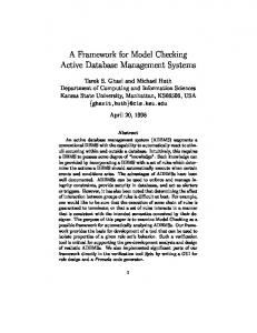
Figure 1: the proposed wave simulator and active heave compensation framework for demanding offshore crane operations.
Open-Source Software and Hardware
The adopted motion platform is a type of parallel robot that incorporates three DOFs. It consists of three arms connected to universal joints at the top base. Each joint is actuated by a motor allowing for controlling the corresponding corner of the top base. Given a desired heave position, h, each of the platform corners is raised or lowered to accommodate the position. The motion platform is controlled by using a hardware platform based on a commercial Programmable Logic Controller (PLC). The control architecture, which is shown in Figure 2, fully exploits the standard programming tools and the multi-tasking features offered by the PLC standard. By using the Modbus protocol, a master-slave pattern is set up with the controller acting as a master and the PLC as a slave. The three axes of the motion platform are driven by DC motors (203V). The motors are interfaced to a motor controller. A programmable power supply board is used in order to avoid buying costly H bridge circuits. This board can be remotely controlled from the PLC via Profibus. The motor revolution is controlled by means of inverters. TEMPLATE DESIGN © 2008
www.PosterPresentations.com
xs_new = xs_old + ki
Profibus
xs_new
Actuation Thread
xs - xc -
δxd
PID
xc
Tz, Tθ, Tϕ, TA
z
ki
ϕ, θ
Robotic Arm The robotic arm that is placed on top of the motion platform is a Kuka KR 6 R900 SIXX manipulator. The robot can be operated by the user by means of a standard joystick. In order to efficiently control the robot, the open-source cross-platform communication interface provided by JOpenShowVar [1] is used. JOpenShowVar allows researchers to implement alternative control algorithms according to current needs. The control architecture is shown in Figure 3. It is a client-server architecture with JOpenShowVar running as a client on a remote computer and KUKAVARPROXY acting as a server on the Kuka Robot Controller (KRC). In this preliminary study, the standard kinematics provided with the KRC is used to control the arm. The user program simply works as a driver for the input device and uses the writeVariable method of JOpenShowVar to forward the end-effector’s target position, xt, to a Kuka Robot Language (KRL) program, where the standard KRC inverse kinematics is used to calculate the desired joint angles θt. Remote Computer User JOpenShowVar Program
KRC KRL KRC Inv. Actuator θ t kinematics Program
CrossComClient xt
writeVariable
xt
KUKAVARPROXY
TCP/IP
Figure 3: JOpenShowVar allows for controlling the robotic arm by using the standard kinematics provided with the KRC. Alternatively, different control methods can be implemented according to current needs.
Integrated Control System The integrated control system architecture is shown in Figure 4-a. It is a client-server architecture with the input device running as a client and communicating with a server where the logic of the control algorithm is implemented. The sever is implemented by following strict real-time criteria including multi-threading and synchronised methods. • Wave generation. Random sinusoidal generators are used to reproduce the waves effect. • Heave, roll and pitch detection. An accelerometer sensor is used. The raw data of the movements, d, is collected and received by an Arduino controller board.
JOpenShowVar
δxd
θa
δxd θa
UDP
Figure 2: to control the motion platform, a master-slave architecture is used with the controller acting as a master and the PLC as a slave.
θa
TCP/IP
+
Motion Platform (PLC)
Robotic Arm
ki Client
Motion Platform
k (scaling factor)
α
Accelerometer
i Input device (Joystick)
ϕ, θ
d Arduino Receiving sensor data Low-Pass Filter
Kinematic Model
z
Signal Sinusoidal generators
Modbus
PLC (Slave) ModBus
https://github.com/aauc-mechlab/WaveSimulator Motion Platform
Motion Platform
USB
In order to give researchers the possibility of testing alternative control algorithms for maritime cranes in a realistic and safe laboratory setup, a waves simulator and active heave compensation framework for demanding offshore crane operations is proposed. The underlying idea is shown in Figure 1. The system is composed of an industrial robot, the Kuka KR 6 R900 SIXX (KR AGILUS) manipulator, and of a motion platform with three degrees of freedom (DOFs). The motion platform allows the simulation of wave impacts, while the robotic arm can be manoeuvred by the user with a standard joystick. An accelerometer is embedded on the platform in order to monitor the wave contribution. This same contribution is given as a negative input to the manipulator’s control algorithm so that active heave compensation methods can be realised. The system can be used for both research and training purposes.
Computer (Master)
Server Control Thread
Input Device Thread
Scope of Work
Figure 4: (a) the proposed integrated architecture; a client-server model is adopted; (b) the physical motion platform and the adopted robot.
• Input device. A standard joystick is used as the input device on the client side. Each DOF of the joystick corresponds to a translational axis in the workspace of the manipulator. The joystick signal, i, is scaled with a scaling factor, k, to fit the robot’s workspace. • Server. Control Thread: the current global robot’s end-effector position, xc, can be obtained by using the following transformation matrix, Tc:
the highlighted time segment.
Tc = TzTθ Tφ TA
where Tz is the heave transformation matrix, Tθ is the pitch transformation matrix, Tφ is the roll transformation matrix and TA is the arm transformation matrix. At each control iteration, a set point, xs, is determined for the robot’s end-effector as follows: xsnew = xsold + ki
where xsnew is the new set point and xsold is the set point from the previous control iteration. Successively, the difference between xsnew and xc is calculated so that the corresponding sampling point configurations, δxd, are obtained. In order to generate well-suited trajectories a Proportional Integral Derivative (PID) controller is used for each translational axis. Actuation Thread: it is used to communicate with the Kuka robot. This thread receives δxd and uses the writeVariable method of JOpenShowVar to send the actuation values to the robot. In addition, the actual joint configuration, θa, is read by using the readVariable method of JOpenShowVar and sent back to the Control thread. Simulations and Experimental Results The physical motion platform and the adopted robot are shown in Figure 4-b. A time plot for the robot’s end-effector position is shown in Figure 5-b. Active compensation is performed except for
Figure 5: a time plot for the robot’s end-effector position is performed.
Conclusions and Future Work A flexible framework that allows for reproducing in a laboratory setup the challenging operation scenario of controlling offshore cranes is presented. In the future, different alternative control algorithms may be tested [2]. References and Acknowledgements [1] F. Sanfilippo, L. I. Hatledal, H. Zhang, M. Fago, and K. Y. Pettersen, “JOpenShowVar: an open-source cross-platform communication interface to kuka robots,” in Proc. of the IEEE International Conference on Information and Automation (ICIA), Hailar, China, 2014, pp. 1154 – 1159. [2] F. Sanfilippo, L. I. Hatledal, H. Zhang, and K. Y. Pettersen, “Amapping approach for controlling different maritime cranes and robots using ANN,” in Proc. of the IEEE International Conference on Mechatronics and Automation (ICMA), Tianjin, China, 2014, pp. 594–599.