Proceedings of IDETC/CIE 2008
Proceedings of the ASME 2008 International Design Engineering Technical Conferences & Computers and ASME 2008 International Design Engineering Technical Conferences Information in Engineering Conference & Computers and Information in EngineeringIDETC/CIE Conference 2008 3-6, 2008, New York, USA August August 3-6, 2008, NewBrooklyn, York City, New York
DETC2008-50086 A WEB-BASED ENVIRONMENT FOR DOCUMENTATION AND SHARING OF ENGINEERING DESIGN KNOWLEDGE
Justin A. Rockwell, Paul Witherell, Rui Fernandes, Ian Grosse, Sundar Krishnamurty University of Massachusetts Amherst Department of Mechanical and Industrial Engineering Amherst MA 01003
[email protected],
[email protected],
[email protected]
Jack Wileden University of Massachusetts Amherst Department of Computer Science Amherst MA 01003
[email protected]
ABSTRACT This paper presents the foundation for a collaborative Webbased environment for improving communication by formally defining a platform for documentation and sharing of engineering design knowledge throughout the entire design process. In this work an ontological structure is utilized to concisely define a set of individual engineering concepts. This set of modular ontologies link together to create a flexible, yet consistent, product development knowledge-base. The resulting infrastructure uniquely enables the information stored within the knowledge-base to be readily inspectable and computable, thus allowing for design tools that reason on the information to assist designers and automate design processes. A case study of the structural optimization of a transfer plate for an aerospace circuit breaker is presented to demonstrate implementation and usefulness of the knowledge framework. The results indicate that the ontological knowledge-base can be used to prompt engineers to document important product development information, increase understanding of the design process, provide a means to intuitively retrieve information, and seamlessly access distributed information.
companies distributed across multiple countries. For example, an Apple iPod consists of components produced by Toshiba (China and Japan), Broadcom (Taiwan or Singapore), PortalPlayer (USA or Taiwan), Renesas (Japan), and Samsung (Korea) [2]. Apple was able to achieve innovation (and a competitive advantage) through the successful integration of existing components. Ultimately the integration of components developed by these different companies relied on design teams understanding each other and what factors affected their design and how their design affected others. One of the primary motivators for this trend towards distributed design is increasingly complex designs that require the synchronized contribution of many domain experts. In order to solve complex engineering problems it is necessary for designers to be able to exchange more than simply geometric information. Design intent, rationale, assumptions, in-service requirements, operating conditions, etc. also must be expressed and communicated. Traditionally, engineers have communicated through such means as text documents, data worksheets, slide show presentations, and CAD 2D drawings and 3D models. Although the Internet has allowed distributed collaborators to easily exchange information, the representation (i.e., the organization) of the information (e.g., text documents and data worksheets) has for the most part remained the same. There are multiple shortcomings of this approach: 1) the structure/layout from one document to the next may vary making it cumbersome to quickly locate information; 2) the quality of information documented may be incomplete or inconsistent—moreover, an engineer may have to sift through
1. INTRODUCTION The design process is the organization and management of people and the information they develop in the evolution of a product [1]. The true value of a product is not only the functionality of that product, but also the value that is achieved through the effective organization of resources (people and information). Products that we use everyday have come to fruition through the collaboration between multiple
1
Copyright © 2008 by ASME
multiple documents to get the full understanding of a concept/process; and 3) reuse of such documentation is limited as it requires engineers to manually search, decipher, and interpret information [3]. Consequently, often times these types of documents and the information stored within them become strictly historic records. To address these shortcomings academia and industry have spent significant time and effort developing improved means for representing information in a manner that computers can interpret. In this paper we present a set of modular ontologies for representing engineering design knowledge, which improves documentation of information, increases understanding of the design process, and facilitates useful information retrieval. Through the integration of these ontologies a customizable Web-based environment for documenting and sharing engineering design knowledge is created. In Section 2 an overview of the Semantic Web and its potential in facilitating communication between distributed engineers is presented. A discussion about related work on design repositories is presented in Section 3. Section 4 presents the set of modular design ontologies that make up the framework for capturing and sharing engineering design knowledge. In Section 5 the framework is implemented to document the re-design of a transfer plate. Section 6 summarizes the work presented and discusses further research.
of providing information which is easily understood by humans. The Semantic Web, a developing extension of the Web, aims at giving Web content well-defined meaning with the goal that computers can then automatically process data and information making it easier for humans to easily access information of high value [6]. For this to be realized computers must be able to understand information through the context in which that information exists. Knowledge representation offers a means for computers to process structured data and metadata so that computers can “understand” the meaning of content. Traditional knowledge representation requires that everyone commit to the same definition of concepts. This requirement quickly limits the usefulness of sharing information and the expressiveness of information being shared. One of the basic components of the Semantic Web, the eXtensible Markup Language (XML), enables an arbitrary structure to be added to information through the use of tags that annotate Web content [7]. For these tags to be useful the human who writes the script that processes the data must understand the meaning of the tags. Hence, everyone who uses the tags must share the same vocabulary. This of course means that to share information everyone must conform to a predefined XML schema. A XML schema defines the legal building blocks of the XML document. Agreement upon a predefined schema for representing data is one of the biggest limitations of XML. Sharing information between those that agree upon the schema is facilitated, but integrating information beyond that group of users is not easily achievable: “Stated more succinctly, XML standardizes syntax; it was never designed to even capture, much less standardize, semantics” [8]. Furthermore, making changes to a schema to adapt to an evolving knowledge structure or changing needs can also pose difficulties. Resource Description Framework (RDF) is the second basic component of the Semantic Web [9]. RDF takes advantage of XML-based syntax, but unlike prescriptive XML schema, RDF schema is descriptive. Instead of fixing what data can be captured RDF further enriches the description of the data [10]. The significant benefits of this approach are discussed later. Here the RDF model is presented. RDF provides information about Web content (as metadata) so that concepts are associated with a unique definition. The meaning of data is expressed through sets of RDF triples, each consisting of a subject, a predicate and an object. These triples can be conceptually thought of as similar to the subject, verb and object of a sentence. The assertion of a RDF triple says that some relationship, indicated by the predicate, holds between the things denoted by the subject and object of the triple [9]. This can be represented graphically as in Figure 2.
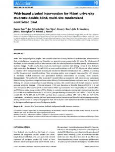
2. THE ROLE OF THE SEMANTIC WEB The Internet and its related developing technologies have, and will continue to, greatly facilitate information exchange domains and between domains. This is of particular benefit to engineers as multidisciplinary design and the integration of concepts and information from beyond the engineering domain become necessary for successful design solutions. Here an overview of recent Web technologies is presented. To begin Figure 1 presents the Semantic Web Layer Cake. Although not all aspects of Figure 1 are discussed this Figure illustrates how the Web technologies build upon each other.
Figure 1: Semantic Web Layer Cake (Used with permission from [4]) The World Wide Web (herein shortened to Web) is a network of information that uses interlinked hypertext documents distributed across the Internet to display text, images, videos, etc [5]. The Web primarily serves the purpose
Figure 2: RDF triple (Used with permission from [9])
2
Copyright © 2008 by ASME
characteristics of an ontology. Benefits of using OWL include: • OWL is easy to share—since OWL is based on RDF and XML it is easy to share and process information regardless of programming language or operating system • OWL fully exploits the ability to uniquely identify concepts through URIs • OWL can represent distinguishing relationships • OWL is easily extendable. Suppose an existing ontology in OWL provides 90% of what is needed, but the remaining 10% is critical. Multiple ontologies can be linked together via URI to extend an existing ontology and add additional concepts [15] • OWL is intrinsically setup to evolve with the Semantic Web
Thus, a RDF document makes assertions that particular things (subjects) have properties (predicate) with certain values (objects). Each part of the triple (subject, predicate, and object) is identified by a Universal Resource Identifier (URI). URIs enable concepts to be identified by defining a URI for where that concept exists on the Web. In this manner, ambiguous meanings of content can be avoided through the specification of a unique URI. For example, it becomes possible for a computer to determine if a “Table” is referring to a piece of furniture or a set of data arranged in columns and rows by following the relationships between “Table” and other concepts as specified by the RDF triples. For example, if one of the relationships (the predicate) is “Material” and it has a value (the object) of “Wood” then it is likely that “Table” refers to a piece of furniture. This is possible despite the fact that upfront the computer does not know what a “Table” refers to. Inferring this type of distinguishing information is not possible in languages, such as XML, where predefined information tags are utilized. The power of RDF is that RDF schema is decoupled from the data. This means that the schema can be changed and extended as needed without affecting existing stored data. Moreover, RDF provides a knowledge representation that can be decentralized across the Web (and thus across the Globe) and easy to share since it does not require a commitment to a single vocabulary. Layered on-top of RDF is “the third basic component of the Semantic Web, collections of information called ontologies”[11]. Gruber defines an ontology as the “explicit specification of conceptualization” [12], where “conceptualization” refers to the entities that may exist in a domain and the relationships among those entities [13]. RDF formally represents relationships between information so that computers can process these relationships between different concepts on the Web. For computers to infer a useful understanding of the relationships between such information (as in the “Table” example presented above), ontologies are required. Ontologies formally define classes, subclasses, and relations among entities. Relations are formed among entities by assigning properties to classes and requiring subclasses to inherit properties from their respective super-class(es). Ontologies allow computers to make distinctions between information (e.g., (in)equality relations, restrictions) and inference rules in ontologies allow for more advanced relations to be made. As humans we are capable of understanding implicit relationships between information. For example, if told “Paul bought a new car” we understand that it is then likely that Paul has his driver license, Paul is of the legal driving age, and Paul has some means of financial resources. Computers can not infer such implicit relationships. What ontologies offer is a means to explicitly represent these otherwise implicit relationships so that computers can then seemingly “understand” the information. As of 10 February 2004 the Web Ontology Language (OWL) became a World Wide Web Consortium (W3C) Recommendation [14]. A W3C Recommendation is a specification or set of guidelines that has received the endorsement of W3C Members and the Director. OWL is a semantic extension of RDF and is used to express the
There are three sublanguages of OWL: 1) OWL Lite, 2) OWL DL, 3) OWL Full (see W3C documentation for detailed explanation of differences [14]). For this research OWL DL was chosen. OWL DL is based on Descriptive Logic and offers the most expressiveness while remaining computable and decidable (all computations will finish in finite time) [14]. This logic-based language provides a means for accurate and consistent distinctions to be made. Although much more could be written about the Semantic Web, this hopefully provides the reader with enough details to recognize the power of the Semantic Web in improving documentation, sharing, retrieval, and reuse of engineering design knowledge. Understanding the basics of the Semantic Web will clarify later discussion of implementation of the engineering design ontologies. Before presenting the engineering design ontologies the approaches that others have taken to improve engineering information exchange and reuse are briefly discussed. 3. RELATED WORK Both academia and industry have recently taken interest in developing better means for capturing, storing, and retrieving engineering design information. The National Institute of Standards and Technology (NIST) has developed a design repository [16] which uses an object-oriented representation language. Artifacts are represented as objects and relationships. Classes, attributes and inherited class attributes are utilized to determine the attributes of an artifact. The values of objects and relationships can be universal resource locators (URLs) which reference another data structure(s) or string text. For representation of geometry, ISO 1030, commonly know as STEP (Standard for the Exchange of Product Model Data), is used. Mapping from the generic schemata into XML is done to provide improved exchange of knowledge. In [17] a design repository system for documentation and retrieval of design knowledge is presented. Based on the Functional Basis developed in [18], primarily product functional models are represented (although other product
3
Copyright © 2008 by ASME
automate design processes; and 4) storage of information in an easily sharable and extendable manner (i.e., OWL)
description such as dimensions, color, material, etc. are allowable) in a PostgreSQL database with a JSP (JavaServer Page) Web interface, and a Java standalone application for design knowledge entry. Artifact subfunctions are represented through input artifact, input flow, output flow and output artifact. Allowable information types for product attributes are text, numerical, or Boolean. In [19] this repository was updated to include additional artifact attributes, a new C++ application and user interface, and a switch to accommodate XML representation. Commercially available there are a number of product data management (PDM) systems and requirements management (RM) systems that combine to offer similar capabilities as design repositories. PDM systems and methods provide a structure in which information about processes can be stored, managed, and controlled. RM systems structure and link requirements to the product throughout the design process. As mentioned in [20], RM and PDM systems must work together since they support the same processes. However, integration of these systems is difficult and due to duplicate information, inconsistencies can arise. Recent research in ontologies in engineering design [21-30] has also demonstrated the feasibility and potential usefulness of ontologies for documenting engineering design knowledge. In [22] an ontology for capturing, storing, and retrieving engineering analysis models is presented. Later in [23] that work was extended to include documentation of design optimization models. In [25] an assembly design knowledge-base was created. After review of these related works, some notable shortcomings of these approaches are: 1) representation of engineering knowledge in a language that requires a predefined vocabulary limits the ability to share and evolve the knowledge-base without loss of instantiated knowledge, making the extendibility and flexibility of the approach limited; 2) documenting knowledge through the use of text descriptors does not sufficiently represent concepts in a manner that is easy for humans or computers to understand; 3) use of closed systems can be difficult and problematic when attempting to integrate information from multiple systems; 4) the issue of connecting information throughout the entire product development process has not been sufficiently addressed; and 5) retrieval of knowledge still needs to be improved upon. We present a suite of modular ontologies, represented in OWL DL, that capture information from various domains within engineering design and integrate that information to create a coherent and consistent knowledge-base that allows for the entire design process to be represented. Since these ontologies are modular our framework allows for customized ontological knowledge-bases to be easily created. Salient features of using such an ontological knowledge-base include: 1) prompts for engineers to document important product development information; 2) efficient, user-intuitive means for retrieval of information within the knowledge-base; 3) storage of information in a computable manner, allowing for design tools that reason on stored information to assist designers and
4. ENGINEERING DESIGN ONTOLOGIES The following sections present an overview of the engineering design ontologies and the proposed approach for creating customized knowledge-bases. 4.1 Ontologies for Engineering Design An ontological framework for capturing and sharing engineering knowledge has been developed and consists of a suite of modular ontologies. The usefulness and reusability of modular ontologies are well known in computer science and in knowledge engineering [13, 31-32] and here are being applied to engineering design. By creating a suite of modular engineering design ontologies an entire product development knowledge-base can be customized for each end-user (e.g., company) by adapting existing ontologies from the library. Additionally, with a foundation of well-defined engineering ontologies established it is possible to extend an ontological knowledge-base by creating ontologies that are compatible with the existing ontologies. Many different engineering design methodologies exist and most companies have developed product development methods specific to their company. In general most engineering design methodologies include the four main phases of design as identified by Pahl and Beitz [33]: 1) Planning and Clarifying the Task, 2) Conceptual Design, 3) Embodiment Design and 4) Detailed Design. This work seeks to enhance communication between designers within and between all of these design phases by providing an ontological platform for designers to document and share information. Table 1 gives a brief description of the ontologies that form the suite of engineering design ontologies. Although not an exhaustive set of engineering ontologies, these ontologies provided a foundation for building a complete engineering design knowledge-base. Note that our goal is not to deliver a complete engineering design knowledge-base application. Rather we seek to develop this semantic framework of engineering design ontologies sufficiently to demonstrate improved documentation and sharing. In this work, to ensure well-defined ontologies, the development of the engineering ontologies followed the four guidelines below to guard against redundant information and provide a consistent foundation that can be built upon. 1.) Each ontology must define one engineering domain—it is important to not extend out beyond that domain. The level of abstraction for any domain can vary, but must be clearly defined. This research employs a narrow definition of each ontology. For example, the Form, Behavior, and Optimization ontologies should not include the class ‘People’. The concept of people (designers) is an enterprise concept and belongs in the Organization ontology. All other ontologies then link to the Organization ontology to use information from the ‘People’ class.
4
Copyright © 2008 by ASME
Ontology
Description
Type
Product
Ontology that classifies the products that a company sells. The components and assemblies that make up the product are associated with the product. Along with manufacturing processes, materials, weight, price, and purchaser(s). This is an enterprise ontology and as such is adaptable to satisfy the needs of different companies.
Enterprise
Assembly
Captures detailed information about the assemblies of products. Identifies individual components within assemblies and products that use the assembly. Connects to any function, form, behavior, or optimization models applicable to the assembly.
Engineering
Component
All individual components are cataloged here. Identifies component function, form, behavior, and optimization models. Identifies component materials, weight, size, etc.
Engineering
Function
Form
Behavior
Decision Support
Optimization
Functional model information about components, assemblies and products. Input and output energy, materials, and signals. Used to decompose overall product function into sub-functions. Ontology is based on functional basis developed in [18]. Detailed information regarding the form of any component, assembly or product. The information varies from text description to links to CAD files of the object. Form models could be any type of 2D or 3D models. Associated models that affect the form of the component are identified. Any existing behavior and optimization models are identified. The assemblies and the products that the part belongs to are identified. Form model captures sufficient information to support the manufacturability of an artifact. Detailed information about the behavior of any component, assembly or product. The different analysis techniques are classified and the details of the model are captured (i.e. for a FEM: element type, applied force, model symmetries, etc. are captured). Model inputs and model outputs (results) are recorded. Higher level information such as modeling assumptions and idealizations are also captured. Based on the work from [22] Decision making methods are classified creating a library of different techniques for the decision maker to use. Information captured in other ontologies is integrated together to facilitate a decision made based on the collective knowledge. Design alternatives, evaluation criteria and decision rationale are all documented. The optimization technique(s) used for any component, assembly, or product is classified. The inputs and outputs of the optimization are captured. If the optimization produces a change in geometry, the new form and behavior models are associated. Based on the work in [23]
Engineering
Engineering
Engineering
Engineering
Engineering
Requirements
Requirements are defined here based on customer needs. Both hard and soft product (or component) requirements are specified.
Enterprise
Organization
Includes classes such as 'people', 'projects', and 'tasks'. This ontology is intended to capture mainly project management information. This is an enterprise ontology as the nature of the information captured in this ontology is likely to vary widely for each company.
Enterprise
Table 1: Modular ontology description and type
5
Copyright © 2008 by ASME
2.) Each ontology must be created with the entire design process in mind. The relationships between information must be carefully thought out and considered. 3.) Redundant information must be prevented in order to avoid ambiguous information. Since many smaller ontologies will be linked together to create a knowledge-base, it is possible that two different ontologies could be capturing the same information. Therefore, care must be taken to ensure that the same information is not duplicated in different ontologies. 4.) Consistency of the information captured is paramount rather than the completeness of information.
4.2 Ontology Type The engineering ontologies described provide a general representation of the concepts associated with the design process. These concepts are generic in the sense that, regardless of the application (what product is being developed) or company/domain technical jargon, the engineering concepts don’t change. By linking together ontologies from the library a customized knowledge-base that mimics the design process can be constructed. To facilitate this process, each ontology in the library is broadly classified into four major groups, namely: 1)Engineering Ontologies are knowledge structures that concisely represent well-defined engineering concepts (e.g. engineering analysis models). Engineering Ontologies are not company specific and the class structure and properties of the ontology are, for the most part, static. 2)Enterprise Ontologies, on the other hand, are company specific ontologies. The class structure and properties of these ontologies will vary from company-to-company but still must remain compatible with the Engineering Ontologies. For example, a product ontology is an Enterprise Ontology as each company produces different products and has an existing means of classification of their product line. To make Enterprise Ontologies easily adaptable to the specific needs of companies these ontologies are setup in more of a template manner. 3)Standard Ontologies are a set of ontologies that define basic scientific concepts. Such concepts would include measurement units and material properties. Developing a set of standardized ontologies that represent basic scientific concepts is critical to fully exploiting the benefits of improving communication through ontological knowledgebases. 4)Specialized Ontologies provide application-like capabilities to act on stored information and automate design processes. These ontologies provide very specific utility and typically involve the use of logical rules to help automate processes. In Section 2.4 Specialized Ontologies are further discussed.
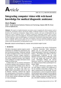
Each of the ontologies presented in Table 1 were created using Protégé 3.3.1 ontology editor [34-35]. The number of classes, properties, and relationships in each ontology vary for each ontology depending on the completeness of each ontology and complexity of the concept. The more complete and complex ontologies, such as the Optimization Ontology, have over fifty classes and just as many properties, while some of the simpler ontologies have five to ten classes and ten to twenty properties. Figure 3 is a part of the class hierarchy for the Optimization Ontology.
Figure 4 illustrates these four different types of ontologies and how they build upon each other.
Figure 4: Types of ontologies
Figure 3: Class Structure of Optimization Ontology
6
Copyright © 2008 by ASME
created and how the engineering information within the knowledge-base is connected.
4.3 Implementation of Engineering Design Ontologies As mentioned, information captured in OWL is easy to share across the Web since OWL enables multiple ontologies to be linked together via Web URIs to combine distributed information. Using Apache Tomcat [36], an opensource Web-based Java application server, the modular ontologies presented in Section 4.1 were made accessible via the Web. The modular ontologies were then be linked together by specifying a URI. Additionally, for this research we have utilized the units ontology developed at the NASA Jet Propulsion Laboratory by linking to their ontology [37]. By linking ontologies together the class structure, properties, and any instantiated knowledge are incorporated. With multiple ontologies connected, relationships can be specified between distributed information and logic rules can be implemented to reason on the combined knowledge-base.
5.1 Case Study Introduction The case study is an industry inspired problem that focused on the re-design of a transfer plate for a circuit breaker intended for aerospace applications. The main objective of the re-design was to minimize weight. Constraints on the re-design were 1) Deflection - .010 inch MAX at any point 2) Yield stress of the part may not be exceeded at any point. 3) Manufacturing process must be stamping 4) Must operate between -67 oF and 320 oF 5) Mounting means and force location cannot be changed-- all other dimensions are free. Five student groups from a senior level design class at the University of Massachusetts Amherst were presented with this problem and developed five different possible redesigns. The five re-designs developed, along with the existing design, are illustrated in Figure 5.
4.4 Customized Ontological Knowledge-base As the ontological framework currently exists, there are three different approaches to customize a knowledge-base. The first and easiest method is through different combinations of the modular ontologies. This is achieved by connecting ontologies through the Web, which allows for the scale of each knowledge-base to easily vary. The second way to customize the knowledge-base is by adjusting the Enterprise Ontologies, which enables the knowledge structure to be tailored to the very specifics of a company. Information about product-lines, employees, vendors, customers, suppliers, etc. can all be customized. This does require changes to the class structure and properties of the Enterprise Ontologies. But since ontology editing tools, such as Protégé, are not difficult to use it is actually possible for someone with little computer science knowledge to edit the Enterprise Ontologies to match existing company conventions. The final approach to customize a knowledge-base is to include Specialized Ontologies that build upon the general Engineering Ontologies. Specialized Ontologies will provide a means for extending the breadth and utility of the knowledge system. An example of a Specialized Ontology is highlighted in the innovation technologies developed in [24]. In [24] an ontology that greatly facilitates the implementation of TRIZ was developed. This TRIZ ontology can be included in any knowledge-base as a design innovation tool to support designers during the conceptual design phase. A customized ontological knowledge-base created through this approach actively links to the Engineering Ontologies, adapted Enterprise Ontologies, Standardized Ontologies, and Specialized Ontologies to draw distributed information together to be used by designers. A significant outcome of this is that changes can be made to the individual modular ontologies and these changes will automatically be reflected in the knowledge-base without lose of instantiated knowledge. Section 5 will next illustrate through a case study the implementation of this approach.
Figure 5: Transfer plate design alternatives Each student group produced a technical write-up to explain the details of their re-design. At a minimum, the technical reports were to include information regarding form models, optimization models, and analysis models used to arrive at a solution. For this project no physical testing or prototyping was expected. 5.2 A Customized Knowledge-base for the Transfer Plate The information from the technical write-ups was used to create an ontological design repository to document the re-design of the transfer plate. To do this, first a customized knowledge-base was created by linking a set of ontologies together. Based on the information to be captured the knowledge-base in Figure 6 was created. Enterprise ontologies were customized to represent a circuit breaker product line and include information about the student groups and re-design project. NASA’s units ontology [37] was used and six of the Engineering Ontologies presented were used. In total nine ontologies were linked together by specifying a URI for each ontology. This created the ontological knowledgebase for the transfer plate re-design. 5.3 Case Study Observations With the structure of the knowledge-base created the next step was to use Protégé to manually transfer the information from the student reports into the knowledge-base. This allowed benefits of the ontological knowledge-base to be
5. CASE STUDY The case study of the re-design of a transfer plate is used to demonstrate how a customized knowledge-base is
7
Copyright © 2008 by ASME
compared to the traditional technical write-ups. The following observations were made.
defined input parameters it is quite difficult for someone else to reasonably explain the results or to re-use the optimization model. The use of the ontological knowledge-base emphasizes and prompts the user when needed information is missing to prevent valuable information from being lost. Figure 7 shows the capture of an optimization model with input parameters properly documented and a different optimization model without input parameters documented. Furthermore, the uniform way in which information is captured helps designers document and locate information.
Observations 1- User Prompts help Document Important Information Although it was made clear to the students what information to record, many of the groups failed to capture important design details. For example, most groups sufficiently documented the results from their optimization models, but some of the groups failed to document all of the input parameters for their optimization models. Without well-
Knowledge-base for Transfer Plate Function
Form
Organization Component
Behavior
Product
Optimization
Decision Support
Measurement Units
Enterprise Ont.
Standard Ont.
Engineering Ont.
Relationship between information
Figure 6: Set of modular ontologies linked together to create knowledge-base for transfer plate Incomplete information—missing input parameters
Optimization model with incomplete documentation of input parameters
Optimization model with input and output parameters identified
Figure 7: Optimization models captured using ontological Knowledge-base
8
Copyright © 2008 by ASME
Figure 8: A transparent design process
The individual engineer can traverse through the knowledgebase moving between bits of information that logically fit together for that individual. Traditional data-bases often organize information by business function (e.g., by department) rather than in the context of its meaning or in ways that people think. The classification of information and the relationships between information in an ontological knowledge-base improves cross-departmental and crossdisciplinary sharing of information by enabling users to easily locate and re-use captured engineering knowledge in this manner. Additionally, since the information is stored in OWL it is foreseeable that computer automated retrieval will be improved due to emerging technologies that take advantage of the RDF relationships so that computers can better understand meaning to process information more effectively.
Observation 2- Increased Understanding of the Design Process In addition to the prompting and documenting of relevant information, the use of the ontological knowledgebase enables the identification of relationships and connection of information throughout the design process. Using the knowledge-base, it becomes possible to quickly understand the product evolution path and the design processes. This is because linking knowledge together via URIs allows disparate information to be reasonably related. Thus, the ontological knowledge-base improves model reuse by making the design process transparent so that the knowledge gained at all levels can be used by others. Figure 8 shows a schematic representation of the resulting transparent design processes. All re-designs of the transfer plate have been documented along with the designs selected for further consideration and the rationale behind each design selection decision. The established relationships allow the user to follow the process from one domain to the next. Observation 3- Information Retrieval is Intuitive Locating information within the ontological knowledge-base is intuitive. The knowledge-base is intuitive because the relationships allow different users to end-up at the same information in totally different ways based on how the individual thinks. Unlike in technical write-ups, information is not scattered but rather it is classified by content and meaning. If a designer knows the exact bit of information needed, searching or navigating to that information is straight-forward. If the designer does not know the exact piece of information sought after, then the defined relationships between information helps the user traverse through information to find the information of interest. Figure 9 conceptually illustrates how the same information can be located via different paths. The boxes represent information and the connecting arrows represent the connectivity relationships. From the user’s standpoint it feels as if the knowledge system has been customized for that individual.
Figure 9: Traversing information based on relationships Observation 4- Access to Distributed Information is Seamless Information can be automatically integrated so that designers have direct access to information of interest. This is shown through the use of the decision support ontology (see Table 1), which documents the rationale behind design decisions. For the transfer plate case study the decision support ontology was used to select which re-designs to further develop. Go/No-Go screening [1] was implemented and then Pugh’s decision matrix [38] was used to compare the selected re-designs to the existing design. Within the decision support ontology the design alternatives from the Form ontology and the design
9
Copyright © 2008 by ASME
reviewing information through traditional technical write-ups is a much more cumbersome process that requires the designer to manually sift through documentation and does not ensure the consistency of information available to each decision maker. From the case study presented, observations suggest that an ontological knowledge-base helps to: 1) Prompt document design information in a standardized manner which supports thorough knowledge capture and improves understanding of knowledge 2) Improve the user’s ability to locate information 3) Facilitate sharing information via the Web 4) Support automation of design processes through the use of logical inference tools such as SWRL
requirements (both hard and soft requirements) from the Requirements ontology were identified for Go/No-Go screening. Using the Semantic Web Rule Language (SWRL) logic rules in the form of an implication between an antecedent and consequent were written and implemented [39]. An example of one of the SWRL rules used is illustrated in Figure 10.
6. SUMMARY Globally distributed design has and will continue to change how engineering design is done. The knowledge gained during the design process is of high value and the need for an improved means to effectively document and share this knowledge is well recognized. Thus far the Web has facilitated the exchange of information but the representation of the information has not sufficiently evolved. The Semantic Web provides methods for addressing some of the shortcomings of current knowledge-bases. Specifically the benefits of using OWL and other emerging semantic Web technologies include: 1) knowledge is documented in a manner that is computable allowing for computers to infer new knowledge from existing knowledge; 2) knowledge is easily shared— agreeing to a predefined vocabulary is not a requirement, making it possible to exchange information without a long term commitment to a single vocabulary; 3) since the RDF schema is decoupled from the data the knowledge-base can evolve with the type of knowledge being captured; 4) it is easy for a domain expert to modify ontologies through the use of ontology editors such as Protégé; 5) OWL and RDF are platform independent. This paper presented the foundation for a Web-based environment for improving communication by formally defining a platform for documentation and sharing of engineering design knowledge. A library of modular ontologies for engineering design was developed and four different means of customization presented. A customized ontological knowledge-base was created by linking the modular ontologies together via the Web. The case study of a practical engineering design problem was detailed to demonstrate the implementation and usefulness of the ontological knowledge-base. The results indicate that the ontological structure of this approach can provide a means to maintain consistent information, while the modular aspect creates flexibility through re-use and adaptation so that industry implementation of such a knowledge system becomes practical. Still, implementation of such a Web-based environment that truly increases cross-department and crosscompany communication will require the: 1) availability of a set of agreed-upon standardized ontologies that represent basic
Figure 10: Example Go/No-Go SWRL rule SWRL rules were implemented to automatically execute Go/No-Go screening by checking the hard requirements against each alternative. Design alternatives 1, 2, and 3 of the proposed re-designs were a Go (all hard requirements were met) while alternatives 4 and 5 were a No-Go. SWRL rules then automatically established relationships between design alternatives 1, 2, and 3, and the existing transfer plate design, with an instance of the Pugh’s decision matrix class. All the information about the design alternatives for decision makers to evaluate is now readily available. This type of automation reduces the amount of time spent searching for information and also ensures consistency of information since all evaluators are linked to the same information. Through the Pugh’s decision matrix the designer(s) can evaluate each design alternative based on the evaluation criteria. Since the decision matrix is still connected to all the existing information within the knowledge-base the decision matrix becomes interactive. The designer(s) evaluating the design alternatives can easily access information regarding the form, behavior, or optimization model(s) directly through the decision support ontology. Additionally, detailed information about the evaluation criteria can be accessed directly. This increases understanding of the designs and criteria. Presenting the designer with the distributed information in an easy to access manner facilitates improved evaluation of alternatives. The designer can expand his/her level of understanding of the design alternatives and evaluation criteria in order to make a well-informed decision. This avoids spending excessive time locating information. Since currently we are limited to using Protégé for accessing the knowledge-base and Protégé is not intended to visually display information to engineers Figure 11 illustrates how the decision support ontology keeps the designer connected with the knowledge-base and what a potential user interface could look like to display the captured knowledge. Accessing and
10
Copyright © 2008 by ASME
scientific concepts; 2) increased use of engineering ontologies to include more domains and the testing of these ontologies through larger case studies; and 3) from the designer’s perspective, a user-friendly web-based interface that provides a means to easily interact with the ontological knowledgebase. Currently efforts are being directed toward developing an eXtensible Stylesheet Language Transformations (XSLT) based application programming interface (API) to demonstrate an interface that could be used to instantiate new knowledge and query existing knowledge without using an ontology editor. Although there is still much research to be done to determine the actual capabilities of approach presented, it is predicted that, when fully implemented, the knowledge acquisition system will enable propagation of design information throughout the entire design process and allow for
the growth and evolution of the knowledge-base. It will be able to take advantage of ontologies to promote the capture of both explicit knowledge and implicit knowledge such as rationale, assumptions, and limitations. It will facilitate the classification of information documented within the knowledge-base by content and meaning, making knowledge retrieval intuitive. Also it will lead to increased understanding of engineering models and processes and will allow for the knowledge of domain experts to be incorporated early on in the design process to help detect possible design pitfalls. Acknowledgements This material is based on work supported by the National Science Foundation under Grant No. 0332508 and by industry members of the NSF Center for e-Design.
Figure 11: Decision support integrates information from different ontologies so designers can easily access pertinent information
[4] World Wide Web Consortium, (2005) An Introdcution to RDF, http://research.talis.com/2005/rdf-intro/
REFERENCES [1] Ullman, D. G. , 1997 , The Mechanical Design Process, McGraw-Hill, New York.
[5] World Wide Web Consortium, (1992) About the World Wide Web, http://www.w3.org/WWW/
[2] Linden,G., Kraemer, K.L., Dedrick, J., (2007) Who Captures Value in a Global Innovation System? The of Apple’s iPod, Personal Computing Industry Center, http://pcic.merage.uci.edu/papers/2007/AppleiPod.pdf
[6] World Wide Web Consortium, W3C Semantic Web Activity, http://www.w3.org/2001/sw/ [7] World Wide Web Consortium, (2006) Extensible Markup Language, http://www.w3.org/TR/REC-xml/
[3] Caldwell, N.H.M., Clarkson, P.J., Rodgers, P.A., Huxor, A.P. (2000) Web-Based Knowledge Management for Distributed Design, Intelligent Systems and Their Applications, IEEE, v15, i3, pp. 40-47, May/Jun 2000
11
Copyright © 2008 by ASME
[8]Ray, S.R., Jones, A.T. (2006) Manufacturing Interoperability, J Intell Manuf (2006) 17:681–688
[21]Ahmed, S., Kim, S., Wallace, K. (2005) A Methodology for Creating Ontologies for Engineering Design, Proc. of ASME 2005 IDETC/DTM, Sept., DETC2005-84729
[9]World Wide Web Consortium, (2004) Resource Description Framework (RDF) Concepts and Abstract Syntax, http://www.w3.org/TR/2004/REC-rdf-concepts20040210/#section-Concepts
[22]Grosse, I. R., Milton-Benoit, J.M., Wileden, J.C. (2005) Ontologies for Supporting Engineering Analysis Models, AIEDAM, 19, 1-18.
[10]World Wide Web Consortium, (2004) RDF Primer, http://www.w3.org/TR/REC-rdf-syntax/
[23]Witherell, P., Krishnamurty, S., Grosse, I. R. (2007) Ontologies for Supporting Engineering Design Optimization, J. of Computing and Information Science in Engineering, June 2007, v7, i2, 141-150.
[11] Berners-Lee, T., Hendler, J., Lassila, O., (2001) The Semantic Web, Scientific American Magazine, May 17, 2001
[24]Fernandes, R., Grosse, I., Krishnamurty, S., Wileden, J., (2007) Design and Innovative Methodologies in a Semantic Framework, In Proc. of ASME IDETC/CIE, DETC200735446
[12]Gruber, T.R. (1992) Toward Principles for the Design of Ontologies Used for Knowledge Sharing, In Int. J. of HumanComputer Studies, 43, 1992, 907-928.
[25]Kim, K.-Y., Yang, H., Manley, D. (2006) Assembly Design Ontology for Service-Oriented Design Collaboration, Computer-Aided Design & Applications, v3, no. 5, 2006, 603613
[13]Farquhar, A., Fikes, R., Rice, J. (1996) The Ontolingua Server: A Tool for Collaborative Ontology Construction, Knowledge Systems, AI Laboratory [14] World Wide Web Consortium, (2004) OWL Web Ontology Language Overview, http://www.w3.org/TR/2004/REC-owl-features20040210/#s1.1
[26]Kitamura, Y., Roles of Ontologies of Engineering Artifacts for Design Knowledge Modeling, Proc. of 5th International Seminar and Workshop Engineering Design in Integrated Product Development, Sept. 2006, Gronow, Poland, pp. 59-69, 2006
[15] World Wide Web Consortium (2004) OWL Web Ontology Language Use Cases and Requirements, http://www.w3.org/TR/webont-req/
[27]Nanda, J., Simpson, T.W., Kumara, S.R.T., Shooter, S.B., (2006) A Methodology for Product Family Ontology Development Using Formal Concept Analysis and Web Ontology Language, Journal of Computing and Information Science in Engineering, v6, i2, pp. 103-113, June
[16] Szykman, S., Sriram, R.D., Bochenek, C., Racz, J.W., Senfaute, J., 2000, Design repositories: engineering design's new knowledge base, Intelligent Systems and Their Applications, IEEE Volume 15, Issue 3, May-June 2000 Page(s):48 – 55 [17]Bohm, M.R., Stone, R.B. (2004) Product Design Support: Exploring A Design Repository System. Proc. of ASME IMECE2004-61746, Anaheim, California, November 13-19
[28]Moon, S.K., Kumara, S.R.T., Simpson, T.W. (2005) Knowledge Representation for Product Design Using Techspecs Concept Ontology, Proc. of the IEEE International Conference on Information Reuse and Integration, , Las Vegas, NV, August 15-17
[18]Hirtz, J., Stone, R.B., McAdams, D., Szykman, S., Wood, K. (2002) A functional basis for engineering design: reconciling and evolving previous efforts, Research in Engineering Design 13(2), 65-82.
[29]Li, Z., Raskin, V., Ramani, K. (2007) Developing Ontologies for Engineering Information Retrieval, In Proc. of ASME IDETC/CIE, DETC2007-34530, Las Vegas, Nevada, September 4-7
[19] Bohm, M.R., Vucovich, J.P., Stone, R.B. (2007), An Open Source Application for Archiving Product Design Information, In Proc. of ASME IDETC/CIE, DETC200735401, Las Vegas, Nevada, September 4-7
[30]Lee, J., Suh, H. (2007) OWL-Based Ontology Architecture and Representation for Sharing Product Knowledge on a Web, In Proc. of ASME IDETC/CIE, DETC2007-35312, Las Vegas, Nevada, September 4-7
[20] Svensson, D., Malmqvist, J. (2001) Integration of Requirement Management and Product Data Management Systems, In Proc. of ASME DETC2001/CIE-21246, Pittsburgh, PA, September 9-12, 2001
[31]Fikes, R., Farquhar, A., Rice, J., (1997) Tools for Assembling Modular Ontologies in Ontolingua, Knowledge Systems Laboratory, Stanford University, Stanford, CA. http://www.cs.umbc.edu/771/papers/KSL-97-03.pdf
12
Copyright © 2008 by ASME
[32] Stuckenschmidt, H., Klein, M. (2007) Reasoning and change management in modular ontologies, Data & Knowledge Engineering, v63, i2, Nov 2007, 200-223 [33]Pahl, G., and Beitz, W. (1997) Engineering Design: A Systematic Approach, Springer-Verlag, Berlin, [34]Gennari, J., Musen, M. A., Fergerson, R. W., Grosso, W. E., Crubézy, M., Eriksson, H., Noy, N. F., Tu, S. W. (2002), The Evolution of Protégé: An Environment for KnowledgeBased Systems Development, http://smi.stanford.edu/smiweb/reports/SMI-2002-0943.pdf [35]Noy, N. F., Sintek, M., Decker, S., Crubezy, M., Fergerson, R. W., Musen M. A. (2001) Creating Semantic Web Contents with Protege-2000, IEEE Intelligent Systems 16(2): pp. 60-71 [36]The Apache Software Foundation, Apache Tomcat, http://tomcat.apache.org/ [37]NASA Jet Propulsion Laboratory, Semantic Web for Earth and Environmental Terminology (SWEET), http://sweet.jpl.nasa.gov/ontology/ [38]Pugh, S. (1991) Total Design: Integrated Methods for Successful Product Engineering, Addison-Wesley, Wokingham, England [39] World Wide Web Consortium (2004) SWRL: A Semantic Web Rule Language Combining OWL and RuleML, http://www.w3.org/Submission/SWRL/
13
Copyright © 2008 by ASME