and can be easily used by remote developers in their windows applications, Web ... models between SolidWorks and Autodesk Mechanical Desktop is realized. ..... The Web-service part of the platform is implemented with Microsoft C#.
A Web Service for Exchanging Procedural CAD Models Between Heterogeneous CAD Systems Xiang Chen, Min Li, and Shuming Gao∗ State Key Laboratory of CAD&CG, Zhejiang University, Hangzhou, 310027, P.R. China {xchen, limin, smgao}@cad.zju.edu.cn
Abstract. It is a challenging issue to exchange procedural CAD models between heterogeneous CAD systems. In this paper, we extend the synchronized collaborative design environment among heterogeneous CAD systems, which we developed previously, to a Web services based platform for exchange of procedural CAD models between heterogeneous CAD systems. First, the realtime exchange of one single operation is extended to the exchange of a complete procedural CAD model between heterogeneous CAD systems. Second, Web services technology is adopted to encapsulate the procedural CAD model exchange functions to a standard interface, which is then released on the Internet and can be easily used by remote developers in their windows applications, Web applications, and so on. Finally, a Web service for exchange of procedural CAD models between SolidWorks and Autodesk Mechanical Desktop is realized.
1 Introduction As products are often developed via different CAD systems by different enterprises, the product data exchange is displaying its appealing importance along with abundant cooperation carried on between enterprises in the modern world. The parametric information, such as features, parameters, and constraints in the procedural CAD models, needs to be transferred in the process of CAD data exchange since it includes the significant design intents which have all along been designers’ main concern. The design intents are the functional requirements provided by customers, i.e., a set of geometric and functional rules which the final products have to satisfy. However the exchange of the parametric information between heterogeneous CAD systems is hitherto a tough problem in the field. In search of a feasible way to exchange the information accurately, though, there have been some efforts worldwide. These works have their own characteristics, advantages but also limits, which shall be described in Section 2 of this paper. Recently, we have constructed a synchronized collaborative design platform based on heterogeneous CAD systems [1, 2]. In this paper we extend the synchronized collaborative design environment that we have developed to a Web services based ∗
Corresponding author.
W. Shen et al. (Eds.): CSCW 2005, LNCS 3865, pp. 225 – 234, 2006. © Springer-Verlag Berlin Heidelberg 2006
226
X. Chen, M. Li, and S. Gao
platform for exchange of procedural CAD models between heterogeneous CAD systems, so that remote users can utilize the platform to exchange parametric featurebased models between heterogeneous CAD systems by a standard interface in their windows applications, Web applications, etc.
2 Related Work In recent years, the exchange of procedural CAD models between heterogeneous CAD systems has attracted increasingly great attention. Outlined here in the following are some of the main works conducted so far. Choi et al. [3] proposed a macro-parametric approach to exchange CAD models between different CAD systems. By analyzing the general commands of several commercial CAD systems (CATIA, Pro/ENGINEER, UG, IDEADS, SolidWorks, and SolidEdge), they set up a series of neutral commands. The standard commands set is a common set of modeling commands [4] that are used in part modeling modules of major commercial CAD systems. Instead of directly exchanging CAD models, their method exchanges the macro command files between different CAD systems through neutral commands. This approach is dependent on whether the macro files of CAD systems provide sufficient information. As pointed out by the authors, the approach is not applicable to Pro/E since the macro file of Pro/E cannot provide the required information. Rappoport [5] introduced Geometry Per Feature (GPF), a method for integration of parametric and geometric data exchange at the single part (object) level. Features can be exchanged either parametrically or geometrically, according to user guidelines and system constraints. At the target system, the resulting model is represented by means of a history tree, regardless of the amount of original parametric features that have been rewritten as geometric ones. By using this method they maximize the exchange of overall parametric data and overcome one of the main stumbling blocks for featurebased data exchange. Some work aiming at extending the international standard ISO 10303 (STEP) [6] to permit the exchange of procedurally defined shape models between CAD systems is being conducted. The specific work includes:
-
• ISO 10303-55: “Procedural and hybrid representation” is out for ballot as a Draft International Standard. The most basic entity defined in ISO 10303-55 is the procedural_representation_sequence, which provides the capability for capturing the precise ordering of operations. Specialized subtypes are also provided for the representation of sequences defining wireframe, surface and solid models (in the last case, CSG operations are available). Although its main intended application is the procedural representation of CAD shape models, ISO 10303-55 is a fundamental resource for the whole of the STEP standard. • ISO 10303-111: “Construction history features” has passed its Committee Draft ballot, and a Draft International Standard version is in preparation. It is being written for the representation of design features. Its scope is based on an analysis of the capabilities of several major CAD systems and of a range of typical
-
A Web Service for Exchanging Procedural CAD Models
227
mechanical engineering parts. It is intended that ISO 10303-111 will provide a future edition of AP203 (‘Configuration controlled 3D designs of mechanical parts and assemblies’) with the ability to capture a range of design features that have been identified as common to all major CAD systems. In addition to academic researches, there are also some feature-based translators developed by companies such as ASPire3D [7], Proficiency [8], Theorem [9], and TTI [10]. A typical case in point is Collaboration Gateway, the translator developed by Proficiency. In Collaboration Gateway, the Universal Product Representation (UPR) architecture is defined and adopted to provide universal support for all data levels employed by today’s CAD systems (It enables an unprecedented level of CAD interoperability through sharing of design intents including features, dimensions, history, assemblies, metal data, and other information). Currently, Collaboration Gateway has been able to support four high-end CAD systems including IDEAS, Pro/ENGINEER, CATIA and Unigraphics. This product has its powerful Web page but does not provide a standard Web service interface for development, in which application developers throughout the world are very interested.
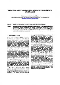
3 Design of the Procedural CAD Model Exchange Platform Based on Web Services 3.1 Underground Procedural CAD Model Exchange System We developed a Synchronized Collaborative Design (SCD) platform based on heterogeneous CAD systems previously [1, 2]. It is a replicated architecture with a distinct CAD system at each site which performs product modeling. In each site there are two translators in addition to an independent CAD system. One is the SMO-to-NMC translator which is responsible for translating each SMO (system modeling operation) just carried out locally into an NMC (neutral modeling command) that will be sent to other sites immediately. Another translator, called NMC-to-SMO translator, is in charge of translating each received NMC from other site into one or more corresponding SMOs of the CAD system. It is these two translators in each site that make possible the realtime exchange of the modeling operations between heterogeneous CAD systems and thus enable the platform to support synchronized collaborative design. In this work, we first extend the platform to make it capable of supporting procedural CAD model exchange between heterogeneous CAD systems. Fig. 1 shows the system structure of the procedural CAD model exchange platform. Although the core ideas and essential techniques are similar between the synchronized collaborative design platform and the procedural CAD model exchange platform, i.e., using Neutral Modeling Commands and original CAD systems’ APIs to achieve the exchange of modeling operations between heterogeneous CAD systems, the implementation details are different. In the procedural CAD model exchange platform, since all heterogeneous CAD systems are on the same site, the local NMC sequence is used to achieve the exchange of modeling operations between different CAD systems in this platform. Moreover, since the procedural CAD model exchange platform deals with
228
X. Chen, M. Li, and S. Gao
CAD system 1 part files
Agent
System1 SMO to NMC Translator
System1 NMC to SMO Translator CAD system 2
CAD system n
Neutral Modeling Command (NMC)
Local NMC sequence
…
Fig. 1. The procedural CAD model exchange platform
the whole model rather than a real time modeling operation in the synchronized collaborative design platform, the translators and NMC set need to be modified as follows: the SMOs are extracted by traversing and parsing the feature tree constructed from the part file of the CAD system instead of capturing real time modeling operation event; three new NMCs are added, which will be described in Section 3.4. 3.2 SOA and Web Services An SOA (Service-Oriented Architecture) is a component model that inter-relates the different functional units of an application, called services, through well-defined interfaces and contracts between these services. The interface is defined in a neutral manner that should be independent of the hardware platform, the operating system and the programming language in which services are implemented. This allows services, built on a variety of such systems, to interact with each other in a uniform and universal manner. Web services technology allows applications to communicate with each other in a platform- and programming language-independent manner. A Web service is a software interface that describes a collection of operations which can be accessed over the network through standardized XML messaging. It uses protocols based on the XML language to describe an operation for execution or data for exchange with another Web service. A group of Web services interacting together in this manner defines a particular Web service application in a Service-Oriented Architecture (SOA). Web services use XML that can describe any and all data in a truly platformindependent manner for exchange across systems, thus moving towards looselycoupled applications. Furthermore, Web services can function on a more abstract level that can reevaluate, modify or handle data types dynamically on demand. So, on a technical level, Web services can handle data much more easily and allow software to communicate more freely.
A Web Service for Exchanging Procedural CAD Models
229
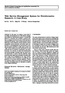
SOA itself is an abstract concept of how software should be put together. It relies on the more concrete ideas and technologies implemented in XML and Web services, to exist in the software form. The distinction between SOA services and Web services lies in their designs. The SOA concept does not exactly define how services are specifically to interact, but just how services can understand each other and how they can interact. Web services, on the other hand, has specific guidelines on how messaging between services needs to interact; i.e., the tactical implementation of an SOA model is most commonly seen in SOAP messages delivered over HTTP. Thus, Web services are essentially a specific subset of how an SOA can be implemented. Through the analysis above, we recognize the significance of SOA and decide to develop a Web service to encapsulate our procedural CAD model exchange system. Once our Web service is published on the Internet, any developers are supposed to find this service through UDDI (Universal Description, Discovery and Integration) and use its function of exchange procedural CAD model to help build their applications or services. In fact, they could simply use it without knowing the details of our procedural CAD model exchange system. 3.3 Architecture of the Web Services Based Platform Fig. 2 shows the architecture of the procedural CAD model exchange platform based on Web services. The left part is the underground data exchange platform, while the right part is the Web service module which provides a service interface without revealing the implementing details of the data exchanging.
The original SCD system CAD 1
Web service Interface
…
Applications
Data Exchange Agent
CAD 2
CAD n
Underground exchange platform
Web service
Fig. 2. Architecture of procedural CAD model exchange platform based on Web services
The Data Exchange Agent module takes charge of dispatching NMCs to a suitable CAD system after the source CAD part file has been uploaded. And then this agent will listen to detect whether the translating work has been done and will send out the transformed CAD part file when assured.
230
X. Chen, M. Li, and S. Gao
Actually, the application module is not a part of this platform. The user application is any module that needs our service. It can be a windows application, a Web application, or even an alternative Web service, if the developers prefer it. Through the interface we defined these applications could use it. 3.4 Construction Details of the NMC Set and the Web Service Interface The original NMC set used in the synchronized collaborative design platform cannot completely satisfy the needs of our procedural CAD model exchange platform. So we extend the NMC set to have four new NMCs: NewCADFile, OpenCADFile, SaveCADFile and CloseCADFile. Now let us see the specific data flow. First, when the source CAD part file has been uploaded to the translating system, the data exchange agent will dispatch an OpenCADFile NMC to the suitable CAD system (according to the source CAD part file’s type). Then, in this source CAD system, we need to: 1) Open the part file and broadcast a NewCADFile to other CAD systems; 2) Traverse the feature tree of the part and extract the SMO sequence and translate each SMO to its corresponding NMC to broadcast; 3) Broadcast a SaveCADFile and CloseCADFile to other CAD systems in the procedural CAD model exchange platform; 4) Close the part file after receiving all acknowledgement messages. On the other hand, in other object CAD systems of the platform, we need to: 1) Create a new part file when receiving a NewCADFile; 2) Translate each modeling NMC to its corresponding SMO; 3) Save the reconstructed part model as a native CAD part file (object file) when receiving a SaveCADFile; 4) Close the part file when receiving a CloseCADFile and send an acknowledgement message (CloseAck) back to the source CAD system and the data exchange agent.
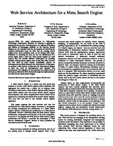
Fig. 3. NMC of source CAD system
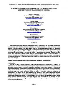
Fig. 4. NMC of destination CAD system (right)
A Web Service for Exchanging Procedural CAD Models
231
At last, the data exchange agent will send back the object CAD part file to the user when receiving the CloseAck. Fig. 3 and Fig. 4 are the two sample NMC output files (record the NMCs the CAD systems send). The Web service open interface is as follows: [WebMethod (Description="send the file to server and get the new file back")] public string TransformFile(string fileName, string fileStr, int srcID, int desID) { … }
The WSDL:
Parameters fileName: the name of the source CAD part file (e.g. a MDT file named example_partfile.dwg). fileStr: the content of the source CAD part file (in base64string format). srcID: an integer number representing the type of the source CAD part file. desID: an integer number representing the type of the destination CAD part file.
232
X. Chen, M. Li, and S. Gao
Return The content of the destination CAD part file (also in base64string format). Function Take in the parameters and transform the source CAD part file to a new CAD part file (the user defines the new file’s type in parameter desID), then return it back. The data exchanging between the Web service and the underground system is achieved in TCP/IP protocol as we take into account its high efficiency.
4 Implementation A Web service for exchange of procedural CAD models between SolidWorks and Autodesk Mechanical Desktop is realized. For each of the two CAD systems, both SMO-to-NMC and NMC-to-SMO translators are implemented with Visual C++ 6.0 and the open programming APIs of the CAD systems (SolidWorks 2003 and MDT6.0). The Web-service part of the platform is implemented with Microsoft C#. And a Web application is also developed to invoke the Web service with a view to checking whether it works well. It is implemented with Microsoft C# too. Now let us have a look at how all these modules work together appropriately. First, the user uploads a CAD part file (push the upload button) on the Web page (Fig. 5) and pushes the transform button to get the specific CAD file that he wants (the user can use the two drop-lists to select suitable source file type and destination file type). Then, when the transform button is pushed down, the Web service is invoked and then it starts the underground exchange platform (the communication between Web service module and the underground exchange platform is built on TCP/IP). Next, the underground exchange platform produces a new CAD file and transfers it back to the Web service module. At last, on the Web page, the user gets the transformed CAD part file returned from the Web service (Fig. 6).
Fig. 5. View of the Web application
Fig. 6. Downloading of destination part file
A Web Service for Exchanging Procedural CAD Models
Fig. 7. View of the source SolidWorks part file
233
Fig. 8. View of the destination MDT part file
The SolidWorks part file before transforming and the MDT part file after transforming are respectively shown in Fig. 7 and Fig. 8.
5 Conclusion and Future Work In this paper, we present a Web services based platform for exchange of procedural CAD models between heterogeneous CAD systems. The features of the platform are: 1) The exchange of procedural CAD models between heterogeneous CAD systems is achieved based on Neutral Modeling Commands and the APIs of CAD systems. 2) Web services technique is used to construct a standard interface for the procedural CAD model exchange platform so that it can be used by remote developers in their windows applications, Web applications, etc. In the future, we will add more CAD systems such as Pro/ENGINEER and UG into this platform and adjust the Web-service structure to provide more powerful functions.
Acknowledgments The authors feel greatly indebted to the financial support from NSF of China (No.60273057), the Trans-Century Training Programme Foundation for Talents by the Ministry of Education of China and Key Project of Science and Technology of Zhejiang Province (2005C21007).
References 1. Li, M., Gao, S., Li, J., Yang, Y.: An approach to supporting synchronized collaborative design within heterogeneous CAD systems. Proceedings, ASME CIE/DETC, (2004) 2. Li, M., Yang, Y., Li, J., Gao, S.: A preliminary study on synchronized collaborative design based on heterogeneous CAD systems. Proceedings of the 8th International Conference on Computer Supported Cooperative Work in Design, Xiamen, China (2004)
234
X. Chen, M. Li, and S. Gao
3. Choi, G.-H., Mun, D., Han, S. : Exchange of CAD part models based on the macroparametric approach. International Journal of CAD/CAM 2 (2002) 23-31 4. Mun, D., Han, S., Kim, J., Oh, Y.: A set of standard modeling commands for the historybased parametric approach. Computer-Aided Design 35 (2003) 1171-1179 5. Rappoport, A.: An Architecture for Universal CAD Data Exchange. Proceedings, Solid Modeling ’03, Seattle, Washington, ACM Press (2003) 6. Pratt, M.J.: Extension of ISO 10303, the STEP Standard, for the Exchange of Procedural Shape Models. International Conference on Shape Modeling and Applications, Genova, Italy, (2004) 7. ASPire3D. http://www.aspire3d.com. 8. Proficiency. http://www.proficiency.com. 9. Theorem. http://www.theorem.co.uk. 10. TTI. http://www.translationtech.com.