29th Annual Precise Time a d Time Interval (PTTI) Meeting
ABSOLUTE TIME ERROR CALIBRATION OF GPS RECEIVERS USING ADVANCED GPS SIMULATORS E.D. Powers and M, Miranian United States Naval Observatory 3450 Massachusetts Ave., NW Washington DC 20392-5420 USA Tel202-762-1451 fax 202-762- 15 11 E-mail
[email protected] J.D. White and J. Brad United States Naval Research Laboratory 4555 Overlook Ave. SW, Code 8151 Washington DC 20375 USA Abstract Preche time transfer eq)er&nen&using GPS with t h e stabd?v’s under ten nanoseconh are common& being reported willrbr the time transfer communily. Relarive calibrations are done by naeasurhg the time error of one GPS receiver versus a “known master refmence receiver.” Z?t$ relative calibration can produce very stable rmults, but this begs the question of “howdoes one calibrate the master reference GPS receiver. In this paper we will discuss the use of advanced GPS simulators to measure the absolute time error of GPS receivers. mis method has the advantage of ccrlibrathg a GPS receiver independent of any GPS qwtem biasar. The use of a GPS simulatot &o allows testing of special conditions of the GPS $ystem, such as year 2000 rollover and the 1024 week epoch rollover.
INTRODUCTION With the advent of the Global Positioning System (GPS), the Precise Time and Time Interval (prrx) community has seen great advances in the ability to compare time and frequency at great distances. In practice, relative time transfer between two timing laboratories has achieved stabilities of a few nanoseconds with averaging times of only a few days 111. Absolute time transfer between two timing laboratories is achieved by comparing one master timing GPS re.ceiver to a secondary receiver over a period of time at a common location. Then the secondary timing GPS receiver is relocated to a remote timing laboratory to conduct the time transfer experiment. It is assumed that this hardware delay calibration of the secondary receiver will remain fured,
193
Form Approved OMB No. 0704-0188
Report Documentation Page
Public reporting burden for the collection of information is estimated to average 1 hour per response, including the time for reviewing instructions, searching existing data sources, gathering and maintaining the data needed, and completing and reviewing the collection of information. Send comments regarding this burden estimate or any other aspect of this collection of information, including suggestions for reducing this burden, to Washington Headquarters Services, Directorate for Information Operations and Reports, 1215 Jefferson Davis Highway, Suite 1204, Arlington VA 22202-4302. Respondents should be aware that notwithstanding any other provision of law, no person shall be subject to a penalty for failing to comply with a collection of information if it does not display a currently valid OMB control number.
1. REPORT DATE
3. DATES COVERED 2. REPORT TYPE
DEC 1997
00-00-1997 to 00-00-1997
4. TITLE AND SUBTITLE
5a. CONTRACT NUMBER
Absolute Time Error Calibration of GPS Receivers Using Advanced GPS Simulators
5b. GRANT NUMBER 5c. PROGRAM ELEMENT NUMBER
6. AUTHOR(S)
5d. PROJECT NUMBER 5e. TASK NUMBER 5f. WORK UNIT NUMBER
7. PERFORMING ORGANIZATION NAME(S) AND ADDRESS(ES)
8. PERFORMING ORGANIZATION REPORT NUMBER
U.S. Naval Observatory,3450 Massachusetts Ave NW,Washington,DC,20392 9. SPONSORING/MONITORING AGENCY NAME(S) AND ADDRESS(ES)
10. SPONSOR/MONITOR’S ACRONYM(S) 11. SPONSOR/MONITOR’S REPORT NUMBER(S)
12. DISTRIBUTION/AVAILABILITY STATEMENT
Approved for public release; distribution unlimited 13. SUPPLEMENTARY NOTES
See also ADA418244. 29th Annual Precise Time and Time Interval (PTTI) Systems and Applications Meeting, Long Beach, CA, 2-4 Dec 1997 14. ABSTRACT
see report 15. SUBJECT TERMS 16. SECURITY CLASSIFICATION OF: a. REPORT
b. ABSTRACT
c. THIS PAGE
unclassified
unclassified
unclassified
17. LIMITATION OF ABSTRACT
18. NUMBER OF PAGES
Same as Report (SAR)
8
19a. NAME OF RESPONSIBLE PERSON
Standard Form 298 (Rev. 8-98) Prescribed by ANSI Std Z39-18
The hardware delay in the GPS receiving equipment is one of the major sources of uncertainty and instability for these types of time transfer experiments. By using advanced GPS satellite simulators to characterize GPS timing receivers, the u n m t i e s could be reduced to less than one nanosecond. Multi-channel GPS simulators that can be used as ideal signal sources for GPS timing receiver calibration are now being produced by many companies. Advanced GPS satellite simulators can produce the same RF conditions that are received from a live GPS satellite, but in a controlled and repeatable manner. In addition, these GPS simulators can be used to characterize a GPS receiver's performance under a wide variety of conditions. Troposphere, ionosphere, multi-path, and selective availability errors can be controlled or set to zero. Any date and time can be simulated to determine whether a GPS receiver can cross-critical date/time boundary conditions such as the coming GPS 1023 epoch rollover. A GPS simulator scenario can be repeated many times to judge the repeatability of the GPS timing receiver. This may be done over a wide variety of environmental conditions to characterize the receiver's stability. SXMZTLATOR HARDWARE CALIBMTION
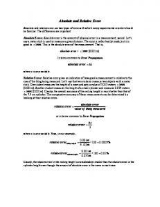
The first step in achieving a highly accurate GPS receiver timing calibration is to calibrate the Calibration equipment. To calibrate the GPS simulatoratherelationship of the one pulse-per-second (1 PPS) reference signal from the simulator and the code phase of the generated GPS signal must be measured. The bi-phase modulated GPS signal code transition occurs in a finite bandwidth and is modulated by timing pulses with rise times of several nanoseconds. Figure 1 shows a high-speed digital oscilloscope plot of an amplified GPS L1 carrier modulated with CA code near the time of the reference one pulse per second. The effect of CIA code modulation (with the navigation data turned off) is that the amplitude of the carrier at the actual time of the reference pulse goes nearly to zero. The ability to properly interpret this code transition is the major limiting factor in this calibration technique. After calibration, same simulators such as the STel7200 have the ability to adjust the reference timing pulse output phase to reduce this error to zero. The Northern Telecom model STR2760 simulator precise timing output cannot be adjusted, but this difference can be carried as a paper calibration adjustment to be removed from the final receiver calibration value.
For the purpose of this paper, three ten-chamellsatelliteNorthern Telecom model STR2760 (NT2760) GPS simulators were used. Experience with the NT 2760 simulator has shown that from a cold start, and without running the internal self-calibrationrecommended by the manufacturer, there can be lo's of nanoseconds oftotal delay variation and comparable code phase differences between the L1 and L2 signals. Using the NT internal self-calibration procedure before the start of each simulation will reduce the total delay variations to a few nanoseconds and the L 1 to L2 variations to about one nanosecond. Table 1 shows the results of our external simulator calibration after the internal calibration has been run for NT simulator serial number 147 over a period of several years. These results show that NT simulator has very repeatable delays when the internal calibration is used. GPS RECEIVER HARDWARE CALIBRATION Once the simulator has been calibrated, the GPS receiver is connected as shown in Figure 2. The use of cables with identical delays in the RF and reference lines simplifies calibration by matching delays in the test and reference paths. A standard GPS simulator scenario is created with a fixed position and nominal
194
ionosphere and troposphere. These factors are included since the modeled ionosphere and troposphere corrections in many receivers cannot be turned off. A standard GPS constellation is used with no errors in satellite positions or satellite clocks. Date
L1 Delay (nsec)
I L2 Delay (nsec)
2f23f95
99.7
I 100.9
I I
3/3/95
98.8
I
I
6118/97
96.8
97*9
10/4/97
98.4
99.2
101797
99.6
99.6
1O/ 14/97
100.0
100.0
100.3
~
~
Table 1* Simulator Calibration Data, C/A codes. The next step in the calibration process is to determine the average measured time difference between the calibrated GPS simulator and the timing GPS receiver outputs. The final step is to apply the appropriate bookkeeping delay corrections for the simulator bias, test cables delays, and the delays for the antenna and antenna cable. STANFORD TELECOM SIMULATOR CALIBRATION METHOD
Stanford Telecom has their own version of this simulator calibration method and has used it successfully to calibrate the masters USNO GPS/UTC monitor receivers [2]. The USNO master GPS/UTC monitor receiver has a built-in calibration mode that is compatible with a calibration function of the STel7200 GPS signal simulator. This allows for a more precise calibration than would normally be possible. SIMULATOR CALIBRATION TEST RESULTS OF AOA TTR-4P
Several attempts to calibrate the Allen Osborne Associate (AOA)Model TTR-4P have been performed since 1995. The calibration data show a run-to-run variation that is significantly larger than the standard deviations of the individual tests. These variations could be as large as 20 or more nanoseconds. Initially some of the changes were thought to have been correlated with temperature changes in the laboratory. To isolate temperature effects, the AOA TTR-4P receiver was placed in a thermal chamber and re-tested at several temperatures. No clear temperature effect was identified, although some of the data pointed to coefficients as large as 1 nanosecond per degree Celsius. In late 1995 it was concluded that more detailed testing was needed to document what temperature effects exist and whether or not they are unique to this particular receiver or whether they are generic to the TTR-4P design. The simulator did not appear to be the cause of the shih,since its calibration number had remained constant over time and a variety of laboratory conditions. However, to increase confidence in it, another experiment was done using a STel5401C receiver. The scenario length was increased to one day to increase the chance of seeing any irreguIarity in the simulator signal. The room temperature was changed
195
from 21°C to 27°C for several hours and then back to 21OC during the run. Within the noise limits of the STel receiver (less than 5 nanoseconds), no changes in the simulator were seen. In 1996 USNO reported an mor in the AOA lTR-4P resulting fkom the phase relationship between the external 5 M I - k provided to the AOA "R-4P and the measured local 1PPS signal. It was thought that the relationships of the external 5 MHz signal and 1 PPS must be held fmed and have no bias to produce consistent time transfet results. This would later be proved only partially correct. In June of 1997 AOA TTR-4P serial number 164 was made available for further simulator calibration testing. A series of detailed experiments were conducted investigating the relationship of the external 5 MHz and 1 PPS signals. The externally provided 5 MHz was offset by 1 mHz to study in detail this USNO reported phase effect. It was discovered that there was indeed a large error resulting from the phase relationship of the externally provided 5 MHz and 1 PPS. Figure 3 shows a time series plot of the measured 1 PPS signal output from the TTR-4P and the internally derived measurements. An obvious measurement error can be seen in these data of up to 24.4 nanoseconds. The period of each cycle shift is not 1000 seconds as might be expected, because the external 5 MHz is multiplied inside the receiver to a frequency of 20.456 MHz. All measurements within the AOA TTR-4P are based on this 20.456 MHz internal clock. The 24.4 nanosecond amplitude of the time error results from a 0 - 180 degree phase shift in this 20.456 MHz signal. Next, the externally provided 5 MHZ reference frequency offset was set to zero and its phase relationship was set to match the externally provided 1 PPS signal to less than 100 picoseconds. The receiver was then reset many times and allowed to acquire the simulated GPS signal. Table 2 shows the results of this experiment. There were many times when the receiver came back to within B few nanosecondsof its previous value; then there were other times the receiver jumped ten or more nanoseconds to a new calibration value. The receiver seems only able to be calibrated to within a 24.4 nanosecond window of Uncertainty.
I Time
I AOATT'R-4PDelayiu(nsec) I
I 11:30
I -162
11:39
-158
11:41
-160
11:43
-154
- 11:45
-152
11:49
-149
1153
-170
1
r
Table 2. AOA TTR-4P Simulator Calibration Data
To confirm these simulator experiments two AOA TTR-4P receivers were run on live GPS satellites for several months and common-view data collected. Several times during this experiment,one of the "R4P's was reset and the time bias changed in a way similar to the simulator calibration results. Figure 4 shows one of the resulting time bias changes in the receiver after a reset.
196
GPS BOUNDARY CONDITION TESTING The NAVSTAR GPS Joint Program Office (PO)funds a consortium of DOD agencies called the Joint Test Agency Test Group (JTAWG). The Satellite Simulator Control Working Group (SSCWG)subpanel of the JTAWG was charged with creating a satellite simulator validation test plan and GPS receiver validation test plan for specific time boundary rollover conditions. The SSCWG members tasked with creating and accomplishing these test plans were the 746th Test Squadron (TS), Naval Research and Development (NRaD) San Diego, Naval Research Laboratory (NRL), and Electronic Proving Ground (IEPG). Listed below are the boundaries and navigation variables, which are being tested. 1.
GPS epoch rollover from GPS epoch 0, week 1023,21 Aug 1999 to GPS epoch 1, week 0,22 Aug
1999. 2. GPS year 2000 rollover from December 31,1999 to January 1,2000. 3. GPS leap year rollover from February 28 to 29,2000. 4. GPS Almanac Week boundaries
GPS 1024 WEEK EPOCH PROBLlEM The GPS week number is contained within the GPS NAV message in the form of a tekbit binary number with a maximum decimal value of 1023, base epoch 0 or (1 1 1111 1111). This 1024-week period is commonly referred to as the GPS epoch. Rollover of this GPS week number may cause anomalous date determination within GPS receivers. The GPS 2-count has no provisions for determining which epoch is current. Week 0 of the first GPS epoch was defined as beginning 0000 hours January 6,1980 the first crossover from week 1023-to-0 will occur 19.7 years later at 0000 on August 22,1999. The GPS data structure does not contain information that would allow a GPS receiver to resolve which GPS epoch it is in. In GPS ICD-200 it states that "At the expiration of GPS week 1023, the GPS week number will rollover to zero (0). Users must account for the previous 1024 weeks." [3,4]
GPS 1023 WEEK EPOCH TESTING
GPS simulators are the only testing tools available that can be used to determine if a GPS receiver will perform properly before, during and af&r this upcoming GPS 1023-week epoch crossover. Several timing GPS receivers were tested to determine if they would operated properly crossing this GPS 1023week epoch crossover. We found that almost all timing GPS receivers with firmware older that 1995 would not fully function properly crossing this 1023-week boundary. The most common problem was that the date would jump back to Jan 6, 1980. Another problem observed was that a receiver might not be able to find any satellites visible because it tries to propagate the GPS almanac backward 19.7 years. One receiver appeared to function crossing the boundary, but the UTC WSNO) to GPS time correction was computed incorrectly because of the 1024 week jump causing a 74microsecond time error FUTURE WORK
The simulator calibration technique is still under going further refinement. We plan to begin using a calibrated anechoic chamber to directly couple the simulated GPS signal directly into the GPS antenna. r
c
197
This will remove the uncertainty in the calibration of the EPS antenna and greatly improve our error budget. We will be testing several new GPS receivers such as the Motorola encore, AOA ” R 6 and the DOD Precision Light Weight GPS receiver (PLGR).
CONCLUSION Calibrations of GPS timing receivers using advanced GPS simulators have the potential to achieve nanosecond level absolute time calibration accuracies. The major limiting factor from a simulator perspective is the measurement of the absolute delay between the modulated GPS signal and the simulator precise timing output. The overall limiting factor is stability of the GPS timing receiver under test. GPS simulators also can be used to test for special boundary conditions coming in the GPS system such as the 1024-week rollover and the year 2000 rollover. [1J W. Lewandowski 1994,”GPS Common-view Time Transfer” in Proceedings of the 25th Annual Precise Time and Time Applications and Planning Meeting (NASA Conference Publication 3267), pp. 133-148.
[2] J. Brad, E. Powers,J. White,and P. h d i s 1996, “Receiver Time Delay Calibration Using a GPS Signal Simulator” PLANS Guidance Symposium,Jan 1996.
131 GPS Standard Positioning Service System Specification,June 1995, second edition, GPS Joint Program Office. [4] ICD-GPS-200 Navstar GPS Space SegmentNavigationUser Interfaces, Rev C, IRN-20 1-001, Oct 1995.
198
,”
Run: 5.00GS/s : f
sample
f.".. /.".]
...................................... . . .
.
.
.
.
:
.
.
.
.
.
.
.
.
.
.
A: l O O . 0 n s
.
:
._. .............................. .............................. ,
~
....
._. ._. ._. .~ j
....
-----5-------f-.+.-
.........................
........................ --_-___T
+'am:~ o ~ . m. .Chiv ~
.
1:
-i-
.~ .~. .
-
i.'o.o. V h
:
I
-
-
-
-
.
:i.. ..o.o. v...
vl 2.'ddns:
,
._. .
j
.
.
. . . . . .
j
.
.
.
.
!
...
Figure 1. CA-code modulated GPS signal at L1 frequencies.
GPS SIGNAL SIMULATOR
SRS 620 lime Interval Counter
RF out
-8.0 ns
GPS Receiver
Figure 2. Timing GPS receiver calibration test setup.
199
1 mHz Ref. Offset -120
-130 -140 0
80
-150
Z
1 -160 -170
'Mw
-180 4oooo
'Y
Ref- ;PS I
40200
L
40300 40500 SECONDS
40100
40800
40600
40400
40700
Figure 3. AOA TTR-4P extemal offset frequency reference problem.
I
20
1I
10
1I
0
'II ' '
-10
-
I
-20
I - I
LIII I
I
I
I
50725
I
I
I
I # , l I l ,
50726
--
I
I
l I l l , l l t l h 50729
SO727
'liI-I
50730
Figure 4. AOA T R 4 P abrupt calibration change at MJD 50728.
200