tion among LBL, SLAC, Caltech, and many university groups, and recently .... the machine is built and provides insurance against unforeseen problems. 5.
r SLAC-PUB-5261 June 1990 (A/?‘)
AN ASYMMETRIC B FACTORY BASED ON PEP* A. Hutton Stanford Linear Accelerator Center, Stanford University, Stanford, CA 94309, USA M. S. Zisman Lawrence Berkeley Laboratory, Berkeley, CA 94720, USA
Abstract The study of rare and CP-violating B meson decays is well suited to a high-luminosity e+e- collider. For studying certain decay processes there are also substantial benefits associated with asymmetric beam energies, which give a moving center of mass for the B mesons. We describe a design for a 9 GeV x 3JGeY B Factory in the PEP tunnel that would operate initially at a luminosity of 3 x 1033cm-2s-1. Technical problems include issues related to high currents (e.g., beam instabilities, feedback systems, lifetime degradation and detector radiation power dissipation) and those related to the heteroenergetic beams (e.g., beam separation, beam-beam interaction and detector requirements). Issues requiring R&D effort are identified.
1. Introduction It is now generally accept.ed that the best facility to study rare CP-violating B meson decays is a high-luminosity electronpositron collider in which the particles have different energies.l Such a B Factory based on the PEP storage ring at SLAC has been under study for about two years, originally as a collaboration among LBL, SLAC, Caltech, and many university groups, and recently joined by LLNL. The names of the articipants in this study can be found in two internal reports, Bl3 which cover the design activities in more detail than can be contained in this paper.
2. General The project consists of two rings of equal circumference, both housed in the PEP tunnel. The High Energy Ring (HER) has a nominal energy of 9.0 GeV while the Low Energv Ring (LER) has a nominal energy of 3.1 GeV. An initial luminosity of 3 x 1O33 cm-*s-l with possible enhancement up to 1O34 cm-*s-l, is required ;or an asymmetric storage ring at the Y(4S) resonance. The design must be ‘conservative’ so that the initial luminosity can be achieved soon after turn-on. The injector will be the SLC, which has filling rates achieved today that meet the requirements for the B Factory. (This scenario does not preclude use of SLC for R&D for future linear colliders.) The infrastructure of PEP will be used wherever possible. The HER will use the PEP magnets while the LER will use some parts of the PEP vacuum system. The facility must be designed and built as a “factory,” which means either adopting design parameters that are tried and tested or providing flexibility when we are obliged to operate in an unknown regime.
3. Parameter Choices The luminosity L, in an asymmetric collider is given by*
where [ is the beam-beam tune shift, r is the aspect ratio, I is the beam current, E is the beam energy, /3; is the vertical beta function at the IP and the other symbols have the usual significance. With equal tune shifts and beam sizes at the IF’. the expression in curly brackets must be equal for both beams. A conservative value of 0.03 has been adopted for the beambeam tune shift for both beams in both planes; practically every electron collider has reached this value. Flat beams (r z 0) are’ preferred, because the synchrotron radiation produced in the Interaction Region (IR) is about a factor of ten less for flat beams than for round beams.4 This is because the angular divergence at the IP is smaller, reducing the beam sizes in the IR quadrupoles (which are also weaker), and thus minimizing the quadrupole synchrotron radiation. The smaller divergence also reduces the angle needed to separate the two beams. Finally an additional benefit is that the angular divergence of the synchrotron radiation is reduced, thereby easing the masking problems. Given the distance to the nearest quadrupole, the values of /?G were chosen to ensure that the chromatic aberrations can be corrected. The smallest value must also be greater than the bunch length of 1 cm. The ratios of horizontal to vertical eniittances and beta functions at the IP were chose: to be 25. comfortably less than the emittance ratio achieved routinely in ” PEP. A larger ratio would be easier for beam separation and for backgrounds, so this is a conservative choice. Table 1. Machine Parameters HER LER Particle Electron Positron Energy 9.0 3.1 3 x 1033 Luminosity Tune shift .03 .03 RF frequency 476 Number of bunches 1746 1746 Bunch spacing 1.26 1.26 1.5 3.0 4 37.5 75.0 P* Separation Horizontal 2.14 Beam current 1.48 3.9 x 1O’O 5.6 x 10” Particles per bunch Vert. emittance 1.8 3.6 Horiz. emittance 46 92 Vert. sigma at IP 7.4 7.4 Horiz. sigma at IP 186 186
Ge\ C*-*S-’
MHz m cm cm
nm.rad nm.rad v mm
These considerations lead to the parameter list for the col. lider shown in table 1. The single bunch current is less than that already achieved in PEP at the same energy. The new challenges are the high total current and the large number of
* Work supported by Department of Energy contracts DE-AC03-76SF00515 (SLAC) and DE-AC03-76SF00098 (LBL) Contributed to the 2nd European Particle Accelerator Conference. Nice, France, June 12-l 6. 1990.
Table 2. Comparison of Interaction Regions
radiation power Total no. of > 4 keV photons/crossing reaching beampipe
Crab Crossing
Head-On Flat
Head-On Round 3
0.42 kW
85.7 kW
715 kW
0.34
0.152
94.0
bunches. The choice of positrons for the LER was to minimize the possible deleterious effects of ion trapping on collider performance by avoiding its occurrence in the lower energy of the two rings. . -_
-100
-50
0
I 00
100
50
CENTIMETERS
W,ih?
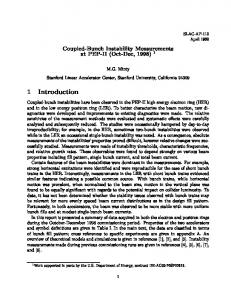
Figure 1. Crab interaction region geometry.
4. Interaction Region Layout An interaction region with a crossing angle and crab crossing inherently creates the least synchrotron radiation but is totally untried. We believe that the beam dynamics must be studied in detail, the collisions simulated, and a test carried out on an existing collider before we could conservatively base our design on it. The head-on crossing scheme is based on the horizontal S-bend layout, which separates the masking of the two beams and is easily convertible to a crossing angle design if beam dynamics studies permit us to adopt this solution. We are continuing .to study both options and are designing the facility to be compatible with either insertion. The global parameter list is already the same for both insertions and we are proceeding towards a unified layout that can be converted with a minimum of difficulty. This capability will be available when the machine is built and provides insurance against unforeseen problems.
-40 -150 66lPA1
Ql I -100
I -50
I, \ 0
01 I 50
CENTIMETERS
I 100
02 I_ 150 LC,I)II
Figure 2. Flat beam interaction region geometry.
5. Backgrounds
The computer tools to evaluate lost particle backgrounds have now been prepared and the complete evaluation of the detector environment will soon be available.
The total amount of synchrotron radiation produced in the interaction region is the sum of the quadrupole radiation and the bend radiation for both beams. Table 2 compares the present schemes with previous IR layouts. The crab crossing layout (fig. 1) produces the least amount of radiation and the head-on flat beam case (fig. 2) is the next best; both are considerably better than the round-beam cases.
6. The Lattice Arcs Examining all of the possible scenarios lea,ds to the conclusion that the component layout of the present PEP ring provides a range of emittances compatible with all requirements of the high energy ring (HER). The required beam stay-clear is somewhat smaller than PEP (&38 mm by f20 mm compared with f45 mm by f27 mm). We are therefore confident in proposing to reuse all of the PEP magnetic components and their power supplies for the HER.
The numbers of photons hitting the beampipe in these two insertions were calculated assuming that the particle distribution is the sum of two gaussians-the core with the nominal sigmas and the tail with larger sigmas: g=exp{---$---$}+Aexp{--s--s}
The present PEP vacuum chamber will have to be replaced for the HER. The new chamber is being designed for 3 A to permit future upgrades. It is our present intention to adopt a copper vacuum chamber, profiting from the experience at HERA and from the BFI Proposal.’ Copper seems better for thermal conductivity and outgassing, and detailed calculations show that such a chamber will be self-shielding for the synchrotron radiation. Assuming a photon desorption coefficient for copper of 2 x 10e6 molecules/photon (one tenth that of aluminium), the gas load in the HER at 3 A is very similar to that of PEP. The pumping speed required imposes a solution with distributed pumps in addition to lumped pumps. The distributed pumps will be ion pumps in the bends with the possible addition of NEG pumps in the quadrupoles. Removal of the synchrotron radiation power is limited by the heat transfer
where A = 10m4, Bz = 0.65 and B, = 0.1. The vertical tail distribution is considerably larger than the core, corresponding to experience in existing storage rings. The total relative amount of particles in the tail is given by A/B,B, = 1.5 x 10m3. These values reproduce the background conditions at the MAC detector in PEP.5 The backgrounds are presently dominated by bend radiation from the offset beams in the quadrupoles and hence are insensitive to the exact details of the tail distribution. The synchrotron radiation background is shown in Table 2 and is extremely low in the preferred cases. It should be noted, however, that photons scattered back from the beampipe beyond 3 meters have not yet been included; this contribution is being calculated now. 2
to the water (film transfer coefficient), so fins or multiple water passages will be used. The LER will most likely have the same period length as PEP, a choice that still permits sufficient flexibility in the optics. The choice of bending radius will be determined by injection conditions and engineering considerations. We are currently devoting considerable effort to ensuring that the LER has sufficient flexibility to conform with “energy transparency” condi%ions if they prove important.7)8 In particular, room will be left in the lattice for wigglers to control the damping time of the ring.
7. RF and Feedback The RF system must provide 18.5 MV in the HER and 8 hlV in the LER to maintain the bunch length at 1 cm. In addition, the-synchrotron radiation power of 5.5 MW in the HER and 2.7 MW in-the LER must be replaced by the RF systems. The solution adopted has 1 MW klystrons each feeding 2 or 4 single-cell cavities. The 4-cavity solution is easier from an RF power point of view as it only requires an RF window capable of handling 250 kW near the cavity. The 2-cavity solution is better for impedance and cost reasons so a research program is being initiated to develop 500 kW windows. Engineering has begun on laying out an RF module having 1 klystron and 4 cavities but that can easily have an additional klystron added. There is enough space in existing buildings to house these klystrons and the existing transformers have sufficient capacity to power them. An RF frequency of 476 MHz is our preferred choice (onesixth of the Linac frequency) and the detailed cavity shape is being designed. The cavities will be made of copper and the higher-order trapped modes must be heavily damped to reduce the multi-bunch instabilities to manageable levels. We are currently evaluating waveguide couplers on the sides of the singlecell cavities, both by computer simulation and using a model cavity. First results are encouraging. The preliminary design of a feedback system exists that could stabilize multi-bunch instabilities with growth rates of about 3 ms. The system uses a series array of 10 striplines at a central frequency of 1 GHz, each
1/4-X long with connecting transmission lines 1/2-X long. The total power required is estimated to be 3 kW with a bandwidth of 120 MHz.3
8. Summary The present study will lead to a Conceptual Design Report to be published in January 1991 that will also contain a detailed breakdown of cost and schedule. It is intended that the facility be built jointly by LBL, LLNL and SLAC. At the recent workshop on Asymmetric B Factories at Berkeley, it was concluded that ‘there is no known reason to expect that such a facility cannot be built.’ We believe that we are close to demonstrating that we have a totally viable solution.
References 1. ‘The Physics Program of a High-Luminosity Asymmetric B Factory at SLAC’ SLAC-353, LBL-27856, CALT 68-1588 (October 1989). 2. ‘Feasibility Study for an Asymmetric B Factory Based on PEP’ LBL PUB-5244, SLAC-352, CALT68-1589 (October 1989). 3. ‘Investigation of an Asymmetric B Factory in the PEP Tunnel’ LBL PUB-5263, SLAC-359, CALT-68-1622 (hlarch 1990). 4. A. Hutton, ‘The Advantages of Flat Beams in Head-on Collisions.’ Paper presented at the Workshop on Beam Dynamics Issues of High-Luminosity Asymmetric Collider Rings. Berkeley (February 1990). 5. M. Sullivan, UC-IIRPA-88-01 (May 19%) 6. ‘Feasibility Study for a B-Meson Factory in the @RN-ISR Tunnel’ CERN-OO-YY, PSI-PR-90-08 (March 1990). 7. Y. Chin ‘Beam-Beam Interaction in an Asymmetric Collider for B-Physics’, Proc IV lnternational Conference on High Energy Accelerators, Tsukuba, Japan (19S9). 8. S. Krishnagopal & R. H. Siemann, Phys. Rev. D, 41, 2312 (1990).
_