Abstract Application Modeling for System Design Space Exploration Muhammad Waseem, Ludovic Apvrille, Rab´ea Ameur-Boulifa, Sophie Coudert and Renaud Pacalet System-on-Chip laboratory (LabSoC), GET/ENST 2229, routes des Crˆetes BP 193 F-06904 Sophia-Antipolis Cedex France Email:
[email protected]
Abstract The increasing complexity of System-on-Chip (SoC) requires a complete reexamination of design and validation methods prior to final implementation whereas faster system design space exploration is today’s requirement to speed up the design process in order to cope with ‘timeto-market’ constraint. We have introduced SoC modeling approach which mixes simulation and formal modeling and verification methods for efficient design space exploration phase of SoC design cycle. The applications are described as a network of communicating tasks whose behaviors are abstracted. Because applications are abstract, it is possible to significantly increase the speed of simulation, to perform a quick performance analysis and apply static formal analysis techniques at higher level of abstraction. The proposed methodology has been employed in the design of a telecommunication system. A part of the application is modeled as a set of tasks in a modeling language and their behavior is monitored as a waveform of events in a simulation environment.
1. Introduction Design space exploration is the process of analyzing various functionally equivalent implementation alternatives to select an optimal solution. In the traditional top down design approach the designer starts with an informal specification and develops a reference model in some high-level language such as Matlab, C or C++. This model is then verified for functional correctness according to the system specification and is used to get rough estimates of its performance requirements. This initial step is followed by manual or semi-automatic generation of several alternative designs, which are subjected to a series of time-consuming and typically ad-hoc evaluations. Finally the most suitable design is chosen based on various metrics such as performance, cost, power, reliability, and flexibility. For modern
embedded systems, it becomes more and more important to have efficient tools for system-level design space exploration, especially at an early design stage where the design space is very large. Unfortunately, most of the available design space exploration tools are not mature enough to satisfy all these requirements. They are either over-detailed or too superficial for exploration. We present in this paper a methodology for modeling SoC applications at a high abstraction layer. The approach is centered around three principles: 1. Separation of application and architecture 2. Data abstraction 3. Use of simulation and static formal analysis techniques on abstract models Applications are modeled as a network of communicating tasks. There is abstract data processing within the tasks and they are control oriented. There is no reference to underlying architecture. A very simple language called Task Modeling Language (TML) is used to describe the behavior of the tasks. As a priliminary experiment we have designed a TML library and used it to model an application. Rest of the paper is organized as follows. Section 2 describes some related work in system design space exploration domain. Section 3 describes the Task Modeling Language (TML). Section 4 explains TML Library, section 5 describes a case study modeled in TML.
2. Related Work Several methodologies and tools have been intoduced for system-level design space exploration of System on Chip (SoC). Some of them have been studied and mentioned in this paper. ArchAn [2, 3, 8] is an architectural simulation environment in which applications are modeled in an abstract task modeling language and the abstract architecture is modeled
at the cycle-accurate level using a mixture of synchronous language Esterel and C. The approach used in ArchAn focuses on the optimization of hardware architecture by early performance analysis through high-level simulation of the system. However the approach in ArchAn does not describe the application and architecture in an orthogonal fashion. The task modeling language which is used to model a task, includes details of the underlying architecture which mixes the architecture and application models. The ArchAn in not intended for static formal analysis at all although it uses Esterel for architecture models, which has well defined formal semantics. Esterel is used for its synchronous behavior and compatibility with C to easily model architecture components. IMEC has introduced a C++ class library OCAPIxl [9] targeting system design for heterogeneous hardware/software architectures. OCAPI-xl is based on the idea of separation of architecture and application as we are using in our modeling. However in our approach we are not including functionality neither in the application model nor in the architecture model. Instead we are abstracting both as compared to that in OCAPI-xl. Moreover OCAPI-xl concentrates on partitioning of hardware and software and their implementation. We are concerned with modeling rather than implementation. SPADE [6, 7] is a methodology for architecture exploration of heterogeneous signal processing systems. SPADE is built on the idea of separate applications and architecture models and their mapping. These models are abstract and parameterized. SPADE models only Kahn Process Networks, which is based on dataflow semantics. The application modeling in SPADE comprises three coarse grained instructions for computation and data communication. While we have, in addition to computation and data exchange, control exchange and task flow control semantics in the task model as explained in next section. SESAME [5, 1] is an extension to SPADE. SESAME framework aims the potentials of simulation at multiple levels of abstraction. Synchronous Dataflow actors in SESAME model the control flow semantics in the application model. However SESAME is still a simulation environment. It does not consider formal analysis techniques.
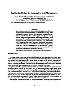
3. Methodology The overall methodology we proposed for system design space exploration phase is depicted in figure 1. It consists of various steps: 1. Abstract application modeling using a simple language called TML (Task Modeling Language) as described in the next section. It is possible either to simulate or perform static formal analysis of task models written in TML.
2. Architecture modeling as a composition of instances of five generic components: CPU, bus, memory, hardware accelerator and input/ouput peripherals. These components are abstract and parameterized through a small set of simple parameters. 3. Mapping associates each task described in TML an execution node in the architecture. 4. Next step consists of refining the application to go for the final implementation.
Application Modeling
Architecture Modeling
Simulation Mapping
Static Formal Analysis
Application modeling on Architecture
Simulation Static Formal Analysis
...
Refinement
Figure 1. Design Methodology The contribution of this paper is focused on application modeling and verifying models using simulation.
4. Application Modeling To model an application at high level of abstraction we have proposed a paradigm called TML (Task Modeling Language) . At this abstraction level we dont consider any architecture on which these applications are to be executed. Also at this level there is no difference between hardware tasks and software tasks because no partitioning is defined yet. There is no data processing details inside the tasks. They are only control oriented without any notion of physical time. However operations within a task model are totally ordered and among a set of tasks, they are partially ordered. The proposed task modeling language consists of following subsets of coarse-grained instructions: • Abstract data exchange • Abstract data processing • Control exchange
• Control flow
EXECI 200
Along with these instructions TML contains virtual channels and events to be declared globally in the system. One can define local variables within tasks for control flow. Each TML variable is a 32-bit signed integer. Some arithmetic, logic and relational operators are provided in TML which are used to manipulate TML variables.
4.1
Abstract data exchange
We have used the notion of virtual channels for the communication among tasks without having any knowledge about the implementation details of the underlying communication infrastructure. Therefore, in TML application models we specify channels for task-to-task communication instead of specifying the hardware model as used by [3]. It is defined at mapping time which virtual channel corresponds to which architectural component. We have considered three types of channels to be introduced in the Task Modeling Language (TML): Type I II III
Read blocking non-blocking blocking
Write non-blocking non-blocking blocking
Intuition Infinite FIFO Shared memory Finite FIFO
For type III a parameter is needed to indicate how many samples can be written before blocking. TML elements associated with virtual channels are: • Channel ch0 2 1: declaration of a channel ch0 of width 2 bytes and of type I. • WR 64 ch0: Write 64 data samples to ch0. • RD 64 ch0: Read 64 data samples from ch0. Above instructions realize a data communication of 64 words each of 2 bytes between two tasks connected by ch0.
4.2
Abstract data processing
This subset of instructions represents the computational complexity of the node while executing applications . The semantics of these instructions depend on the underlying architecture and can be observed after mapping. At application level they can simply be ignored or considered as some fixed local operation of a task. Three different variants of data processing instruction are proposed: 4.2.1 EXECI represents the computations considering all the data manipulations as fixed-point integers. For example
where the parameter 200 represents the number of elementary integer computations consumed by the processing node. It should be noted that this is not the actual no. of cycles consumed by the processing node as proposed by [3]. The value is interpreted differently according to the model of fixed-point execution parameter of a particular processing node in architecture model, which executes the task after mapping. 4.2.2 EXECF is used to model an execution, which carries all the data manipulation in floating point. The instruction is similar to EXECI except the interpretation within the processing node after mapping. Example use is EXECF 200 4.2.3 EXECC is custom execution instruction. For instance, it may be used in a situation where a processing node has a dedicated co-processor for some complex calculations. In that case the processing unit cost function will be used to model behavior of the execution. At application level where we dont consider underlying architecture, the EXEC set of instructions are assumed to consume a fixed number of simulation ticks as explained in section 5.
4.3
Control exchange
Tasks can communicate control information with other tasks in the system. A mechanism is provided in TML for task synchronization and task invocation. For task synchronization, we have events in TML. In the first version we have introduced unicast unidirectional events. An event declared globally in the system is shared between two tasks. Notify/wait semantics are used in TML. Events are used as follows: • Event e: declaration of an event. • NOTIFY e: notification of event (nonblocking). • WAIT e: wait to receive an event (blocking). A task can be requested to execute from another task in the system. This is done using REQ (request) instruction. For example: REQ DSP_NOISE_SUP REQ DCT_algorithm (64)
where DSP NOISE SUP and DCT algorithm are task identifiers, and 64 may be a control parameter. If the invoked task is already active, the request is stored and is served when the current execution terminates. In case of multiple requests to a single task, the requests are stored in a queue and are treated as first come first served. The size of the queue may be specified in task definition as a local parameter.
4.4
Control flow
To model the behavior of an application, the Task Modeling Language contains basic control structures as provided by high level programming languages. The conditional execution of a TML code is carried out using classical IF-ELSE structures. The example use of condition structure in TML is illustrated below: IF var = 50 THEN EXEC 2000 RD 16 ch2 ELSE NOTIFY e ENDIF The repetition structure in TML is same as in high-level languages. The proposed format for repetition structure is shown below: REPEAT N TIMES ... END REPEAT where N can be a 32-bit immediate value or a TML variable.
5. TML simulation environment We have implemented a simulation environment for modeling applications in TML based on SystemC library [4]. Various constructs in SystemC are helpful to simulate TML. For instance, SystemC threads have been used to represent tasks, TML virtual channels are simulated using SystemC primitive channels and SystemC events are used to simulate the control exchange subset of instructions in TML. For each TML instruction we have implemented a corresponding template function which models the behavior of that instruction. For example the TML instruction RD 2 ch is written as task.RD(2, ch); where task is the task identifier (task ID) and RD is template function with two parameters. Similary EXECI 100 is written as task.EXECI(200). Each task is modeled as a SystemC SC T HREAD process.TML virtual channels are derived from SystemC sc f if o. The length of these channels is parameterized in case of type III, while for type I, the length is prefixed to
some maximum no of samples to simulate an infinite FIFO. In this simulation environment we have used 8, 16 and 32bit wide virtual channels. SystemC Events are used to represent NOTIFY/WAIT instructions. REQ is also simulated as an event in SystemC environment. The EXEC instructions at application level are simulated as if they consume some fixed number of simulation ticks. CRC
Convolutional Encoder
Interleaver
Modulation Mapping
IFFT
Figure 2. Broadcast Channel Encoder
The actual interpretation of EXEC is observed when they are modeled in an application mapped on some architecture, where they are a function of the number of cycles consumed by a processing node. C++ control statements are used to model control flow in TML. In TML specifications there is no notion of physical time but there is order among different TML operations. In order to visualize the interactions among tasks for simulation purpose, we have assumed that each TML instruction takes one tick, where a tick can be defined as a simulation parameter(e.g 1 ns) and can be changed accordingly. Some additional functions are also provided in the simulation environment, for example a uniform random number generation function is implemented to model data dependent situations where the exact number of operations is not known prior to running an application and is dependent on some input data. START() and STOP() utility functions are meant to trace the execution of a task on waveform. getParameter() receives parameters from REQ instruction. It is important to mention that SystemC based TML simulation environment is a kind of very simple straightforward mapping on an immediate architecture i.e. “one task-one execution node” and “one TML channel-one bus”. It is intended for debugging and pre-analysis of TML descriptions.
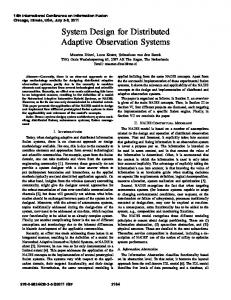
6. Case study: WIDENS WIDENS (Wireless Deployable Network System) is a European project for the implementation of ad-hoc mobile communication networks for public safety organizations. As a case study, we started from the specification of different services offered by the mobile terminals. These services are written in C and Matlab. We were interested to model certains functions of mobile terminals in TML. Among these functions, we have chosen OFDM modulation/demodulation at physical layer: we have modeled Broadcast Channel Encoder routines in TML. The block diagram of the dataflow is shown in figure 2.
c
CRC Table
CRCbit
CRC Table
crc
CRCbit
Conv_code_init
Initialization tasks
Conv_code_init
FFT_init
Mem_alloc
FFT_init
Mem_alloc
Interleaver_init
Interleaver_init Broadcast Channel Encoder
Broadcast Channel Encoder
CRC8_in
CRCTable_in
CRC8 CRC8_out Ccode_in
Application tasks
CRC8
Conv_code
Conv_code
ccode11Table
Ccode_out Symb_in
OFDM_mod
interleaver_tx
Symb_out FFT_out 8-bit channel
OFDM_mod 16-bit channel
FFT_in x_temp
Radix2_FFT
Temp_task y_temp
32-bit channel
Radix2_FFT
Temp_task
REQ
Figure 4. Virtual channels
Figure 3. Request Graph
This dataflow is modeled using 12 TML tasks. 5 tasks model the functional blocks named application tasks in figure 3, some are used for initialization of lookup tables and buffers at system startup. BCH Encoder is the main task which requests other tasks using REQ in a sequence. Some tasks further request others. The task request graph is shown in figure 3. Each arrow represents a REQ instruction. Virtual channels for data communication among tasks are shown in figure 4. In this example, we have used 8, 16 and 32-bit wide channels of type I. We started from the functional specifications of the application written in C language. An example routine in figure 5(a) shows a part of the functional model of convolutional encoder according to WIDENS specifications. From these specifications we have modeled the convolutional encoder in SystemC based TML simulation environment as shown in figure 5(b). The task Conv code(task ID=t8) receives parameter values from the main BCH Encoder task (task ID=t main) as shown at line 6b and 7b. The while loop at line 6a is modeled as TML REPEAT loop which is represented by for loop at line 8b. At line 7a external memory is being acceses via a pointer, which is modeled as TML RD operation from channel Ccode in shown at line 10b. We have assumed that each arithmetic, logic or relational operation is equivalent to EXECI 1. The for loop at line 8a12a is collectively represented by some EXECI operations. EXECI(8) at line 11b models eight times logical shift operation at line 9a and EXECI(24) represents three operations
in if statement’s condition repeated 8 times. The execution within if block at line 10a is data dependent. To model this block, we generate a random number of executions i.e EXECI between 0 and 8 as shown at line 13b. An array read at line 13a is equivalent to reading a sample using TML RD as shown at line 15b. Finally external memory write is done using pointer at line 14a and 15a which are modeled as channel write (WR) operations at line 17b and 19b. The example we have presented here to elaborate the application modeling involves a given specifications as detailed functional model written in C language. However these specifications can be in any higher level languages like Matlab, Simulink or even in natural language. To visualize the execution of TML tasks we have used the VCD dump trace mechanism provided within SystemC. After execution, a VCD file is generated which is used to visualize task activation/deactivation, channel read/writes and executions of tasks. An execution trace of CRC8 task is shown in figure 6. SystemC clock ticks are shown to refer events during the execution. Waveform SystemC.BCH Encoder indicates the activation of Broadcast Channel Encoder task. At point A, CRC8 is requested to execute using REQ. At the same time BCH Encoder starts writing to channel CRC8 in. It continues to write 16 samples to the channel. CRC8 starts reading samples at point B from the same channel. At point C, the CRC8 out channel is read by the BCH Encoder. Since it is type I channel, it is blocked because it is empty at point C. Meanwhile CRC8 keeps on reading samples from CRC8 in and performs executions using EXECI as shown by waveform
1a conv_code(u32 numbytes, u8 *inPtr, u8 *outPtr, u8 puncturing){ 2a u32 state, i; 3a u8 c, out, bit =0; 4a u8 *offset = outPtr; 5a state = 0; 6a while(numbytes-- > 0){ 7a c = *inPtr++; 8a for(bit=0;bit>= 1; 10a if ((c&(11)&1; 16a /* Do Puncturing HERE!*/ 17a } 18a } 19a }
1b SC_THREAD(Conv_code) //task ID=t8 2b { 3b t8.START(); 4b int numbytes,puncturing; 5b int i,RND; 6b numbytes=t8.getParameter(t_main,1); 7b puncturing=t8.getParameter(t_main,2); 8b for(i=0;i