Abstraction and Extensibility in Digital Logic Simulation Software Richard M. Salter and John L. Donaldson Computer Science Department Oberlin College Oberlin, OH 44074
[email protected],
[email protected] ABSTRACT Students of Computer Organization should be able to “learn by doing” at all levels of computer design. Digital logic circuitry is frequently taught using simulation software, however such platforms are often limited to exposing only a narrow range of design levels. This paper describes how, in the new multilevel simulation system DLSim 3, we are able to incorporate abstraction and extensibility to present the many levels of complex circuit designs in a single environment: from low level combinational and sequential circuits, through models of complete CPUs. Among other features, DLSim 3 is able to accomplish this by providing three different types of circuit abstraction: cards, chips, and plug-ins. Using DLSim 3, students recognize the uniformity of system structure, as well as the principles of abstraction that link the various levels of design.
Categories and Subject Descriptors K.3.2 [Computers and Education]: Computer and Information Science Education—computer science education; K.3.1 [Computers and Education]: Computer Uses in Education—computer-assisted instruction; B.6.3 [Logic Design]: Design Aids—simulation
General Terms Design, Experimentation
Keywords Logic Design, Simulation, Abstraction
1.
INTRODUCTION
One objective of any good computer organization course is to demonstrate how a complete CPU can be designed using only gates as fundamental building blocks. However, the vast structural complexity present in any reasonable CPU architecture makes it challenging for students to appreciate the unifying concepts that are foundational to any such
Permission to make digital or hard copies of all or part of this work for personal or classroom use is granted without fee provided that copies are not made or distributed for profit or commercial advantage and that copies bear this notice and the full citation on the first page. To copy otherwise, to republish, to post on servers or to redistribute to lists, requires prior specific permission and/or a fee. SIGCSE’09, March 3–7, 2009, Chattanooga, Tennessee, USA. Copyright 2009 ACM 978-1-60558-183-5/09/03 ...$5.00.
architecture, and which appear at all the various levels of abstraction. This challenge is made greater by a lack of pedagogical tools that uniformly address structural design at every level. Many excellent GUI-based logic simulation systems have been developed and are available for download (Masson [8] is an early example; see [2, 15], for comprehensive, though dated, summaries; recent additions include JLS [10], Digital Works 3.0 [1] and Logisim 2.1.6 [3].) These systems are very useful for studying basic combinatorial and sequential circuits. While they generally all provide some abstraction mechanism (“black boxes”) that permits circuit reuse and multilevel construction, they are limited by their GUIbased environments to relatively small models. Some systems, (JLS and Logisim, for example) scale by providing a fixed library of high-level elements such as flip-flops, registers, memories, etc. While permitting more advanced circuit design, they have limited functionality. When the course moves on to consider higher level designs, such as busses and CPUs, logic simulation systems become less useful. While we know that the products of the logic level must be there to provide the necessary functionality, for the sake of controlling complexity we no longer worry about their fine structure. Consequently we move on to other, higher-level, teaching tools to drive home the details of those levels. Unfortunately, the change in level of abstraction has the unintended side-effect of creating a disconnect in student minds. It is difficult for students to appreciate the underlying structure of the CPU-level as logical circuitry. More importantly, the principles of abstraction, and the structural invariants that link the levels and control the complexity (e.g., Tanenbaum’s “virtual machine” concept [13]) become especially difficult to grasp. We have created DLSim 3 [11] to address the wider spectrum of levels present in CPU design. It does this through vertical scalability as well as horizontal extensibility, as described below. In the next section we describe the features that permit DLSim 3 to act effectively as a multi-level simulator. We focus in particular on the plug-in API. We then provide several examples, continue with comparisons to other simulation software, and conclude with a discussion of future work.
2.
OBJECTIVES FOR THE SIMULATION PLATFORM
Students should be able to “learn by doing” at all levels of system design; consequently we wanted to create a unified
platform for studying system structure, from low level combinational and sequential circuits, through design of a complete CPU. DLSim 3 is able to accomplish this by providing three different levels of abstraction. To the abstract circuits commonly available on logic simulation platforms (which we call cards), we add two new abstractions: chips, and plug-ins. These abstraction tools provide two crucial factors necessary to achieve the desired level of expressiveness: • Extensibility. Abstract circuits extend the palette of basic building blocks used to construct larger, more complex circuits. • Scalability. Abstract circuits permit designers to focus on a particular level of design, needing only to understand the functional behavior of lower levels and not their implementation. DLSim 3 has been used to design circuits at all levels, from simple half and full adders, to prototypes of complete 16and 32-bit CPUs, including Mic-1 [13], and MIPS [9]. (See [4].)
2.1
DLSim 3 Abstractions
DLSim 3 builds on its predecessors, adding several significant new features that make it ideal for multi-level use. In this section we describe these features.
2.1.1
Organizing abstraction: the project
DLSim 3 activity is organized around a project that consists of a top-level circuit and its constituent subcircuits represented as cards, chips and/or plug-ins. A single XML file is used to capture the complete description of a circuit and its subcircuits. This file can be used to recreate and reconstruct the entire set of circuits used in a given project.1 A primary goal of DLSim 3 is to provide fluid navigation between a circuit and its abstracted constituents. Two levels of functionality are provided. The splash display permits the contents of a card to be opened for viewing in place by simply double-clicking on it, however a splashed subcircuit cannot be edited. Subcircuits are selected for editing by clicking in one of the left-hand navigation panels. These navigation panels provide immediate access to subcircuits at any depth (see Figure 1). Note that the top navigation panel shows the subcircuits according to their pattern of inclusion, while the lower one is essentially a catalog of the subcircuits used in the project. Although a subcircuit may be duplicated throughout the project, only one prototype is maintained so that an edit to a subcircuit is immediately propagated to all instances at all levels.
2.1.2
Exportable abstract subcircuits
A subcircuit can be added to any other circuit in the current project (so long as a loop is not created) by dragging it onto the canvas from the subcircuit list. In this way, subcircuits extend the palette of primitive circuit elements. Circuits (including compound items containing further subcircuits) may also be exported and reused in other projects. Each of the three types of subcircuit encapsulation provides a different level of visibility and functionality: Cards. A subcircuit may be encapsulated as a card, and may be exported (in binary and/or XML) for use in other 1 The open structure of the XML representation made it possible for DLSim to be used in an NSF-funded project to drive the programming of field programmable gate arrays (FPGAs) [6].
projects. When exported and reused, it and all of its subcircuits will be visible. For example, the 4-bit ALU shown in Figure 1 has several subcircuits that might be useful elsewhere. If one were to export its 1-bit ALU subcircuit as a card, the export would include all cards telescoped into that subcircuit (e.g., the 1-bit addition and logic units and the 2-to-1 mux). Any new project using the 1-bit ALU would automatically include these. Cards provide complete visibility and access to all levels of the design. Chips. Encapsulating a subcircuit as a chip has two effects: 1) All of its constituent subcircuits are flattened to the level of primitive elements, and optimized by removing unnecessary connections; and 2) the chip is opaque, appearing in the circuit list without any of its own subcircuits. For example, if we were to export the 4-bit ALU as a chip, all traces of its subcircuits would disappear. Chips may be inserted into any circuit in the present project without fear of creating a loop. Or they may be saved and inserted into any other circuit. They are complete and closed, behaving functionally as if they were primitive elements. Plug-ins. Chips are ideal opaque “black boxes” for topdown design, but are limited to abstracting circuits created on DLSim’s GUI canvas. Plug-ins are high-level circuit components derived from Java class files which implement the DLSim plug-in interface. In effect, a plug-in is specified similarly to a circuit defined in some hardware description language such as VHDL or Verilog.2 Plug-ins are crucial for achieving the scalability that allows the same tool to operate at both very low and very high levels. Chips and plug-ins extend the utility of the standard logic simulation platform in a number of ways: • A chip or plug-in can be used by instructors as a template for a class assignment. For example, the instructor could supply a simple circuit (decoder, multiplexer, etc.) written as a chip to demonstrate its functionality without revealing its fine structure, and then assign students the task of fleshing out the details to the level of elementary gates. • Chips and plug-ins can be used to support top-down design. For example, in designing a CPU, a high-level view of the CPU can be constructed using chips or plug-ins for basic components such as the ALU, control unit, and register file. One by one, the plug-ins or chips can be replaced by cards until the design is complete at the gate level. • Plug-ins can be used in situations, such as the design of a medium or large scale random access memory, which would otherwise lead to scalability problems if attempted through DLSim’s GUI interface. Plug-ins are described in detail in the next section.
3.
PLUG-INS
The plug-in has proved to be the most powerful of the three abstraction modes provided by DLSim 3. Because they are written in Java, plug-ins can be enhanced with capabilities beyond the requirements of the plug-in interface itself. For example, a plug-in can be used to perform I/O operations, interact with files, or use the keyboard and screen in special ways. A plug-in representing the control store for a microprogrammed CPU, for example, can read the contents of the 2 In fact, compilers that translate VHDL and Verilog into DLSim plug-ins are in progress.
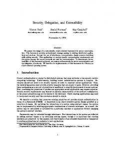
b)
a) c) Figure 1: a) Top-level view of a 4-bit ALU project; b) 1-bit ALU subcircuit; c) Logic unit subcircuit store from a file. As another example, a plug-in could create a console window which could be used to display the contents of circuit components or supply input values to external bus lines. Plug-ins are powerful because they bridge an important divide. On the one hand, their pin-based interface enables the user to insert them into a DLSim 3 circuit like any other component (primitive, card, or chip). On the other hand, their internal operations (i.e., state and computation of output values) are written in Java code. This puts the full power of a high-level programming language in the hands of the plug-in writer. Plug-Ins greatly expand the scale of the circuits which can be simulated in DLSim 3. We have used them in the following situations: • Circuits with a large number of gates. The best example is a random access memory. Constructing, say, a 1-megabit RAM using only low-level components would require many thousands of gates. It would be cumbersome to build and would severely tax the memory and speed of the simulator. It is simple to write as a plug-in, however, and could be used in a variety of projects, such as implementing a 4-megabyte memory from 1-megabit plug-in units. • Circuits with customized views. A view can be used to specify the color and shape of a plug-in. It can also be used to display the current state of the plug-in (for example, the current contents of a register). The view is essentially a GUI for the plug-in, which can be used for interactive I/O with a human user. The power of plug-ins makes it possible to model circuit components at any level of complexity. The instructor may choose the level appropriate for a particular unit of study; that is, which operations should be performed internally by plug-ins and which should be performed by the simulator as a result of the wired connections between components.
For example, in studying CPU design, plug-ins would be used for components such as the ALU and register file. A unit on external bus design would use plug-ins representing a CPU, memory, and I/O interface modules. DLSim 3 gives the instructor the flexibility to match the plug-ins to the appropriate level. An example is given by the implementation of an 8-bit sequential (shift and add) multiplier shown in Figure 2 (based on the description in [14], pp. 344-5.) In this circuit a finite state machine (FSM) program is employed to drive the control unit. The latter is implemented by a general-purpose FSM plug-in which loads a file containing the FSM description. During execution, the plug-in displays the current state and all possible state transitions. A second plug-in type is used for the three registers holding the multiplicand, multiplier and running sum; a third uses Java Swing Spinner controls for convenient user entry of test data. A chip is used to implement the 8-bit adder. Students may first be assigned the job of designing the FSM program, in which case the secondary plug-ins provide highlevel support for the other aspects of the circuit. Later, if focus shifts to the design of those other aspects, students can be assigned the tasks of creating circuits built from logical primitives (what we call “deep circuits”) with the same functionalities as the register plug-ins and the adder chip. These deep circuits may be easily substituted into the existing multiplier implementation, allowing students to readily verify their designs.
3.1
The Plug-in API
To encourage and simplify plug-in creation, DLSim 3’s plugin API provides a strong support platform. All plug-in classes extend a base class containing numerous convenience methods. Plug-in activity is event-driven, and the simplest plug-ins need only specify their input-output functionality.
Figure 2: Sequential multiplier using plug-ins for finite state machine-based control, registers and data entry; a chip is used to implement the 8-bit adder. Plug-ins may also maintain internal state, load initialization files, and/or interact with the user through Swing controls. Authors may provide menu-driven mode options, so that a single plug-in may function in a variety of environments (for example, a register that permits the user to select the bit width for a particular circuit). Plug-in initialization parameters are stored as part of the XML description of the circuit in which it appears. Writing a plug-in involves the following steps: 1. Identifying the pin arrangement for the plugin. Pins may be bundled to simply connections (e.g., a 32-pin input bundle on a 32-bit register plug-in). 2. Overriding the evalState method. This is the callback method for a plug-in input state change. An evalState override may change the internal state of the plug-in, change its output, and/or perform other tasks. 3. Optionally writing a customized view. The View class is used to determine the visual appearance of the plug-in on the design canvas. Plug-in libraries are modeled as jar files that are detected by DLSim upon startup, making them easy to distribute.
4.
EXAMPLES
In this section we consider examples that show how DLSim 3’s abstraction mechanisms enable a wide variety of pedagogical approaches.
4.1
ALU Design
A popular example of modular design is the arithmeticlogical unit, or ALU. The ALU described here (Figure 1) performs basic arithmetic and logical operations on a pair of multibit inputs to produce a result of the same width. This example demonstrates a number of fundamental design concepts that recur often in digital circuits, such as bitslicing, carry-ripple cascading, datapaths, and control inputs and outputs. It naturally decomposes into clearcut subproblems (i.e., half- and full-adders, multiplexers, and single-bit ALUs). A 16-bit ALU is a powerful circuit with 35 inputs and 17 out-
puts, yet the modular approach makes it possible to complete the design while introducing only 8 gates (4 in the multiplexer, 2 in the logic unit, 1 in the full adder, and one in the adder/subtracter), each of which is replicated many times in the final circuit. Using the bottom-up approach, one would first design the 1bit half-adder and multiplexer, then incorporate them into the 1-bit full adder. The latter is then incorporated into the 1-bit adder/subtracter. A similar 1-bit logical unit is constructed and combined with the arithmetic unit to form the 1-bit ALU (see Figure 1). Multi-bit ALU’s are then built by cascading the carry in/carry out bits. This is the approach most readily supported by current logic simulation software. DLSim 3, however, will also support a top-down approach, whereby various stages of decomposition can be encapsulated in chips. At each stage the chip is replaced by a corresponding card containing some or all of the details of that stage’s design, which may in turn require some additional chips. For example, decomposing the top level may involve the instructor supplying a chip opaquely implementing the 1-bit ALU. Students would then build an 8- or 16-bit ALU version from the 1-bit chips using the bit-slice design pattern. When assigned this way, the design pattern itself becomes the focus of the exercise. Implementation of the 1-bit version can continue to follow this top-down approach by supplying chips for half- and full- adders and multiplexers. Alternatively, one could switch to the bottom-up approach. The entire design is made fully visible once the fleshed-out 1-bit ALUs are installed in the multibit circuit.
4.2
Using Plug-ins
Here are some of the smaller plug-in-based applications written by us and our students. None of the plug-ins described here would be feasible as circuits constructed out of primitive elements. Memory: Data and address widths are user-programmable (8, 16 or 32 bits). Cache Simulation: For experimentation with various cache models. A second plug-in collects data for analysis. [12]
Programmable Logic Array (PLA): Simulated PLA circuit programmed via an auxiliary file. Has been used to implement addition and multiplication circuits, and to drive a 7-pin LED. [5] Programmable FPGA Components: FPGA logic block and switching matrix for construction of simulated FPGA circuits. Components are programmed either directly using Java controls or with an auxiliary file. Programmable Finite State Machine (FSM): Implements a FSM control unit. FSM description is read from an auxiliary file. Used to implement the control of the sequential multiplier described above. MIPS-based calculator Comprised of a calculator keyboard and display plug-in that attaches to the DLSim 3 MIPS simulation [4], and a MIPS program to implement calculator functions. [7]
4.3
CPU Models
Among the larger designs undertaken for classroom use are several simulated CPU architectures, each utilizing a library of specialized plug-ins. These include: a) Mic-1 , a microcodebased IJVM (Integer Java Virtual Machine) interpreter ([13], Ch. 4); b) the MicroMIPS architecture ([9], Ch. 5); and c) a pipelined version of MicroMIPS ([9], Chapter 6). Complete descriptions of these implementations are given in [4]. These CPU models serve as the basis for various sorts of project assignments. As in our multiplier example, students may be assigned the job of replacing various plug-ins with functionally equivalent deep circuits, for example the ALU in Mic-1 and MicroMIPS , and the shifter units in Mic-1 . They may also experiment with extensions to the Mic-1 microcode and Mic-1 and MicroMIPS ISA sets. Finally, the more advanced among them may be asked to extend the plug-ins with design enhancements that improve performance.
5.
COMPARISONS
While many of the existing circuit simulators cited above are similar to DLSim 3, specifically in their GUI design and in their support of some form of circuit abstraction, DLSim 3 supports important features that are unique. Among these are: uniform access to all circuits of a project; XML-based representation of circuits; the chip abstraction; and the plugin API. The plug-in API is likely the most significant innovation for unrestricted scaling and extensibility. DLSim 3’s plugin facility provides the hooks for incorporating any element that the user might need, at any level. The plug-in libraries we have developed clearly demonstrate the power of this feature.
6.
CONCLUSION AND FUTURE WORK
Our approach addresses the “fragmentation problem” that strikes many students studying Computer Organization, i.e., making the myriad of topics covered in that class truly unite to form a unified whole. More importantly, by taking such a holistic approach, the conceptual “glue” of abstraction and recursion is illuminated. Our current goal is to build a library of cards, chips and plug-ins which, together with set of progressive laboratory exercises, will provide a complete approach to circuit and CPU design. We also plan improvements to DLSim 3’s sim-
ulation environment by introducing timing factors and simulation scripts. DLSim 3 may be downloaded from http://www.dlsim.com.
7.
REFERENCES
[1] D. L. Barker. Digital works 3.0. http://matrixmultimedia.com/datasheets/eldwk.pdf, 2006. [2] C. Burch. Logisim: A graphical system for logic circuit design and simulation. J. Educ. Resour. Comput., 2(1):5–16, 2002. [3] C. Burch. Logisim 2.1.6. http://ozark.hendrix.edu/~burch/logisim, 2007. [4] J. L. Donaldson, R. M. Salter, A. Singhal, J. Kramer-Miller, and S. Egorov. Exploring CPU design with DLSim plug-ins. SIGCSE’09 Poster. [5] S. Egorov, J. L. Donaldson, and R. M. Salter. Programmable logic arrays: a DLSim implementation. Oberlin College Summer Research Institute, 2008. [6] M. J. Jipping, K. Ludewig, S. Henry, and L. Tableman. How to integrate FPGAs into a computer organization course. In SIGCSE’06: Proceedings of the 37th SIGCSE Technical Symposium on Computer Science Education, pages 234–238. ACM Special Interest Group on Computer Science Education, March 2006. [7] J. Kramer-Miller, J. L. Donaldson, and R. M. Salter. Mips calculator: an integer calculator built with DLSim 3. Oberlin College Summer Research Institute, 2008. [8] A. Masson. Logicsim. http://wuarchive.wustl.edu/edu/ math/software/mac/LogicSim/, 1996. [9] D. A. Patterson and J. Hennessey. Computer Organization and Design, 3rd Edition. Morgan Kaufmann, Palo Alto, CA, 2004. [10] D. A. Poplawski. A pedagogically targeted logic design and simulation tool. In WCAE’07, Proceedings of the 2007 workshop on Computer architecture education, pages 1–7, June 2007. [11] R. M. Salter and J. L. Donaldson. Using DLSim 3: a scalable, extensible, multi-level logic simulator. In ITiCSE’08: Proceedings of 13th Annual Conference on Innovation and Technology in Computer Science Education, page 315. ACM Special Interest Group on Computer Science Education, June – July 2008. [12] A. Singhal, J. L. Donaldson, and R. M. Salter. Cache simulation using DLSim. Oberlin College Summer Research Institute, 2008. [13] A. S. Tanenbaum. Structured Computer Organization, 5th Edition. Prentice-Hall, Upper Saddle River, NJ, 2006. [14] F. Vahig. Digital Design. John Wiley, New York, 2007. [15] G. S. Wolffe, W. Yurcik, H. Osborne, and M. A. Holliday. Teaching computer organization/architecture with limited resources using simulators. In SIGCSE’02: Proceedings of the 33rd SIGCSE Technical Symposium on Computer Science Education, pages 176–180. ACM Special Interest Group on Computer Science Education, March 2002.