ISSN: 2250–3676
T.D.DONGALE* et al. [IJESAT] INTERNATIONAL JOURNAL OF ENGINEERING SCIENCE & ADVANCED TECHNOLOGY
Volume-2, Issue-4, 863 – 870
AC INDUCTION MOTOR CONTROL - A NEURO-FUZZY APPROACH T. D. Dongale1, T .G. Kulkarni2, S.R.Jadhav3, S.V.Kulkarni4, R. R. Mudholkar5 1
Reserch Student, Department of Electronics, Shivaji University, Kolhapur, India,
[email protected] Reserch Student, Department of Electronics, Shivaji University, Kolhapur, India,
[email protected] 3 Reserch Student, Department of Electronics, Shivaji University, Kolhapur, India,
[email protected] 4 Reserch Student, Department of Electronics, Shivaji University, Kolhapur, India,
[email protected] 5 Associate Professor, Department of Electronics, Shivaji University, Kolhapur, India,
[email protected] 2
Abstract Induction motors are becoming popular in industrial surroundings due to the operating performance. Various control techniques are available for induction motor control supported by different drives circuits. In the present paper we report an attempt made to control speed of induction motor using Fuzzy and Neuro-fuzzy technique which provides better regulation of speed. Using Mamdani’s method fuzzy control has been designed. Fuzzy approach has advantages over conventional techniques as demonstrated by the results obtained using Fuzzy technique. An attempt has been made to combine fuzzy technique with neural network for better speed control of induction motor. The results of both techniques are compared. Both techniques provide better performance within their range of control.
Index Terms: Fuzzy Logic, Neural Network, Neuro-Fuzzy, NARMA-L2, Hall Effect Sensor, Speed Control, AC Induction Motor etc. --------------------------------------------------------------------- *** -----------------------------------------------------------------------1. INTRODUCTION There are Different techniques involved for speed control of ac induction motors and innovative techniques emerge out with time. Fuzzy technique is one such innovative technique indented mainly for non-linear system like motor speed control. In this paper we report the demonstration of speed control of AC induction motor based on Neuro-Fuzzy Control. The neural network is used for training the fuzzy model. The fuzzy model is sophisticated tool for speed controlling application. But designing the rules for fuzzy control is something tedious which requires in sight knowledge of system to be controlled [1]. The fuzzy system is designed using Mamdani’s reasoning method. The results obtained using fuzzy control techniques are given as a training data for neural network for optimization purpose. NARMA-L2 controller is a Neuro-Controller available with MATLAB environment that provides the training facility for the system. This Neuro-Fuzzy approach is intentionally added on to existing control algorithm in anticipation to offer better control especially for Non-linear application [2]. Neural networks are emerging techniques for non-linear system. There are many systems designed using Fuzzy approach or/and Neural approach and are reported in many research papers [3, 4]. Here the effort has been made to
combine these two for additional facilities and makes control strategy easier for AC induction motor. The performance of Fuzzy controller is tested. Based on the results of Fuzzy controller the designing of Neural Controller has been made and performance of these two techniques has been compared.
2. SPEED CONTROL OF AC MOTOR- A FUZZY APPROACH Speed controlling of ac induction motor includes many parameters such as initial torque, initial current, voltage etc. Some conventional techniques consider such parameters for speed controlling purpose. Controlling one of these parameters or combination of these parameters provides speed controlling of ac motor. But speed controlling with these parameters is more difficult and render limitations. [5] The hardware implementation of the system based on Fuzzy Logic includes three phase half bridge inverter and 0.5 HP, 1A motor. The PWM sequence for half bridge inverter is generated using PIC 16F877A 8-bit microcontroller. The Hall Effect sensor is used for sensing the speed of ac induction motor. The speed measured in rpm is transformed to speed in rps (rotations per second) and sent serially to ‘Query instrument’ box in MATLAB which is used for real time simulation. Simulink Model for Fuzzy Controller is designed
IJESAT | Jul-Aug 2012 Available online @ http://www.ijesat.org
863
ISSN: 2250–3676
T.D.DONGALE* et al. [IJESAT] INTERNATIONAL JOURNAL OF ENGINEERING SCIENCE & ADVANCED TECHNOLOGY
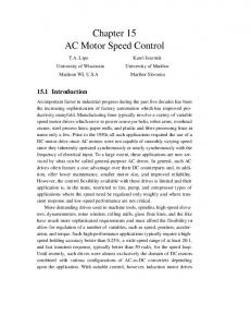
in MATLAB environment. The software residing on the PIC computes the PWM-signal based data given by Fuzzy Controller. The circuit diagram of three phase half bridge inverter is as shown in fig.1.
PM [2] PL[3]
-1 0
Volume-2, Issue-4, 863 – 870
0 1
1 2
2 3
3 4
4 5
5 6
Table-1: Numeric rule base for fuzzy control When these numeric values are transformed in to the labelvalues it gives the desired table of rules as shown in table-II. e
NL [-3]
NM [-2]
NS [-1]
Z [0]
PS [1]
PM [2]
PL [3]
NL
NL
NL
NL
NM
NS
Z
NL
NL
NL
NM
NS
Z
PS
NS[-1]
NL
NL
NM
NS
Z
PS
PM
Z[0]
NL
NM
NS
Z
PS
PM
PL
PS [1]
NM
NS
Z
PS
PM
PL
PL
PM[ 2]
NS
Z
PS
PM
PL
PL
PL
PL [3]
Z
PS
PM
PL
PL
PL
PL
ce
u
NL[-3] NM[-2]
Fig.1: Three Phase Half Bridge Inverter
2.1. Strategy of Designing Rule for Fuzzy Controller Fuzzy approach is mainly intended for non-linear control systems. The critical part of Fuzzy Control is the designing of rule base. For this purpose, the knowledge of a system is essential and it demands for field expertise. However, for Fuzzy Expert who lacks little in the knowledge can use simplest approach for designing rule base, which is basically dependent on algebraic calculation. [1]
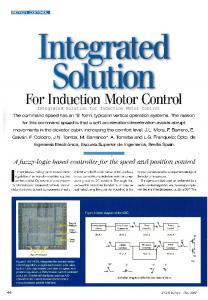
Table-2: Construction of rule base for fuzzy control The seven triangular membership functions are chosen for each input and output variables. The rules are defined according to the matrix. There are 7x7=49 rules encompassing the control strategy. The Fuzzy Inference System (FIS) for speed control of ac induction motor is as shown in fig.2.
For speed controlling of ac motor, basically two inputs error and change of error are considered. The Number of fuzzy sets used for error and change of error are same and this gives rise to a square matrix rule base. Same term set of labels for both error (e), rate of change of error (ce) and output control variable (u) are used as follows- [6-7] Term set = {NL, NM, NS, Z, PS, PM, PL} Number of labels N = 7 NL=Negative Large, NM=Negative Medium, NS=Negative Small, Z= Zero, PS=Positive Small, PM=Positive Medium, PL=Positive Large. The numeric rule base created using simplified approach [1] given is shown in table-I. e ce u NL [-3] NM [-2] NS [-1] Z[0] PS [1]
NL [-3] -6 -5 -4 -3 -2
NM [-2] -5 -4 -3 -2 -1
NS [-1] -4 -3 -2 -1 0
Z [0] -3 -2 -1 0 1
PS [1] -2 -1 0 1 2
PM [2] -1 0 1 2 3
PL [3] 0 1 2 3 4
Fig.2: FIS for speed controlling system The control signals for different speed are obtained by real time MATLAB interface. The FIS is designed with triangular membership function being simple for tuning. The membership functions are tuned in such a way that they provide range of control signals which are applicable to microcontroller. The Simulink design for speed controlling system is shown in fig.3.
IJESAT | Jul-Aug 2012 Available online @ http://www.ijesat.org
864
ISSN: 2250–3676
T.D.DONGALE* et al. [IJESAT] INTERNATIONAL JOURNAL OF ENGINEERING SCIENCE & ADVANCED TECHNOLOGY
Volume-2, Issue-4, 863 – 870
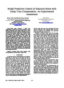
b) Fuzzified output versus Frequency Fig.4: Graphical representation of Observed Values Fig.3: Fuzzy Simulink model for speed controlling system Fuzzy Simulink is designed for getting different inputs. The sensed speed taken from 'Query instrument' is the present speed that is compared with reference. The difference between sensed speed and reference is applied as Error to the Fuzzy Controller. Change of error is not a physical input. It is a difference between previous speed and current speed. Previous speed is held by a memory block. These inputs are applied to the Fuzzy Controller. The control signals from Fuzzy controller are again fed back to the microcontroller using 'To instrument' block. The observations are recorded by sensing sen speed of an ac induction motor using Hall Effect speed sensor. The observations obtained from experimental work are shown in fig.4. These observations were taken using actual interface of three phase inverter with MATLAB. The graph (a) shows the speed of motor (in rps) against fuzzified output for reference speed of 90 being the maximum speed in rps. The set point is selected according to working range of controller. Graph (b) shows the frequency of motor for different ranges of fuzzified output. According to the fuzzified output, the controller adjusts the frequency of operation.
Fuzzified Output
100 80 60 40
Fuzzy Inference provides smooth controlling action over desirable range. Also the settling time required for Fuzzy system is very small. But, problem with Fuzzy controlling is that tuning of Fuzzy Inference is very tedious and requires comprehensive knowledge of the system.
3. SPEED CONTROL OF AC MOTORMOTOR A NEURAL APPROACH Neural networks are the developing techniques which are used for wide range of applications. The learning ability of neural networks and self-adapting adapting algorithms makes it suitable for different applications. Once neural network is trained, trained it is easier to control output at desirable set points [8]. The only necessary condition is to provide training data to the neural network. NARMA-L2 L2 controller in MATLAB is used for Speed controlling application. It has facility of training and adjusting the structure according to the requirement. The two stages involved in training process are System Identification and Control Design stage. [6] • System Identification: NARMA-L2 is a multilayer neural network controller. In this stage the neural network model el of the plant is developed before using the controller. • Control Design:: In this stage, the neural network plant model is used to train the controller. The training samples are provided to the controller for training. The observations obtained from Real Time T MATLAB interface are used as training samples. [9]
20 0 0
20
40
60
Speed (RPS) a) Speed versus Fuzzified output
80
The plant model is nothing but Fuzzy Simulink designed for Fuzzy controlling. The control signals which are future outputs are applied as input to the NARMA NARMA-L2 controller. The NARMA-L2 L2 performs the training using these samples trying for the linearization of the system performance [9 [9-11]. The different specifications required for plant model are as shown in fig.5.
IJESAT | Jul-Aug 2012 Available online @ http://www.ijesat.org
865
ISSN: 2250–3676
T.D.DONGALE* et al. [IJESAT] INTERNATIONAL JOURNAL OF ENGINEERING SCIENCE & ADVANCED TECHNOLOGY
Volume-2, Issue-4, 863 – 870
The Fuzzy Simulink System forms a subsystem to the Neural Controller. The Neuro-Fuzzy approach is derived by a combination of the Fuzzy Subsystem and Neural Controller. The advantage of using neural control is that once it is trained using required data, it works in desired range and controlling mechanism becomes much easier as it provides single output for all the inputs. The algorithm for PIC controller drastically becomes simpler. The time required for training the network depends on the training epochs and number of training samples. For this particular application only 3 training epochs were used. The training data and training performance of neural network are shown in fig.7 and fig.8.
Fig.5: Plant Identification Neural networks are used for training with large amount of data. Here, the effort has been made to train the neural network with minimum amount of data. Training of neural network is much simpler in this system. The other parameters are decided from actual plant requirements. The main approach is to train the network and control the speed of the motor. Fuzzy provides outputs within predetermined range of control signals. But this range is dependent on tuning of controller. If controller is properly tuned it works in the desired range, otherwise controlling goes beyond the range. This makes the tuning a tedious job [12]. The neural controller eliminates this difficulty and makes controlling mechanism much simpler. Fig.5 shows training parameters of neural network.
Fig.6: Simulink model using NARMA-L2 controller
Fig.7: Training data of NARMA-L2
Fig.8: Training Performance
IJESAT | Jul-Aug 2012 Available online @ http://www.ijesat.org
866
ISSN: 2250–3676
T.D.DONGALE* et al. [IJESAT] INTERNATIONAL JOURNAL OF ENGINEERING SCIENCE & ADVANCED TECHNOLOGY
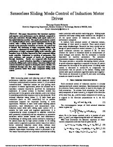
The hardware set up is shown in the fig.9 (a) and circuit diagram of three phase circuit is in the fig.9 (b).
Fig.9 (a): Experimental Set Up of MATLAB Interface of Induction Motor
Volume-2, Issue-4, 863 – 870
4. Result and Discussion Fuzzy control is entirely dependent on designing of rule base. Once it is tuned it provides speed control within operating range. This approach is entirely different than other control techniques. The 7x7 matrix is used for more precise control of speed. The response of this technique shows more sharp performance. The response of Fuzzy technique is as shown in fig. 10 (a, b, c and d) at various speed references. This response is for real time interface of induction motor with MATLAB platform which takes more time than Neuro-Fuzzy response. Neuro-Fuzzy approach is basically designed to provide better solution with Fuzzy control. The combination of these two techniques provides better performance than individual performance of neural and fuzzy. Fuzzy Simulink model is used as a plant for NARMA-L2 controller. Once it is trained it will provide desired controlling action. The response of Neuro-Fuzzy Control is as shown in figure 11(a, b, c and d). But, problem associated with this technique observed during study is that it doesn’t provide expected range of control. On simulative approach has given good results. But for practical interface it is difficult to implement.
(a) Fuzzy response for speed reference 20 rps
(b) Circuit diagram of Three Phase Circuit
IJESAT | Jul-Aug 2012 Available online @ http://www.ijesat.org
867
ISSN: 2250–3676
T.D.DONGALE* et al. [IJESAT] INTERNATIONAL JOURNAL OF ENGINEERING SCIENCE & ADVANCED TECHNOLOGY
(b) Fuzzy response for speed reference 30 rps
Volume-2, Issue-4, 863 – 870
(a) Nero-Fuzzy response for speed reference 20 rps
(c) Fuzzy response for speed reference 40 rps
(b) Nero-Fuzzy response for speed reference 30 rps
(d) Fuzzy response for speed reference 70 rps
(c) Nero-Fuzzy response for speed reference 40 rps
Fig.10 (a-d): Fuzzy response
IJESAT | Jul-Aug 2012 Available online @ http://www.ijesat.org
868
ISSN: 2250–3676
T.D.DONGALE* et al. [IJESAT] INTERNATIONAL JOURNAL OF ENGINEERING SCIENCE & ADVANCED TECHNOLOGY
Volume-2, Issue-4, 863 – 870
controller for cascaded H-bridge multi level Inverter. ISSN: 0975-5462 Vol. 2 no. 2 Feb. 2011. [8]. J. Asha Professor, I.F.E.T. College of engineering, India. Fuzzy logic controller for cascaded H-bridge multi level Inverter. ISSN: 0975-5462 Vol. 2 no. 2 Feb. 2011. [9]. Essam Natsheh and Khalid A. Buragga, Comparison between conventional and fuzzy logic PID controllers for controlling DC motors. [10]. Matlab, Simulink User Guide, the Math Works Inc, 2010 (d) Nero-Fuzzy response for speed reference 70 rps Fig.11 (a-d): Neuro-Fuzzy response
REFERENCES [1]. Tukaram. D. Dongale, T .G. Kulkarni, P. A. Kadam, R. R. Mudholkar, Simplified Method for Compiling Rule Base Matrix, International Journal Of Soft Computing And Engineering (IJSCE) ISSN: 2231-2307, Volume-2, Issue1, March 2012 [2]. Tukaram. D. Dongale, T .G. Kulkarni, P. A. Kadam, R. R. Mudholkar, Fuzzy Model of Thermistor, International Journal Of Applied Engineering Research, Dindigul, ISSN - 0976-4259Volume 2, No 1, 2011. [3]. R. Aruimozhiyal, K.Bhaskaran, N. Devarajan, J.Kanagraj Real time matlab interface for speed Control of induction motor drive using dspic 30f4011. International Journal of computer application , Volume 1 No.5. [4]. Bart Kosko, Neural network and fuzzy system- a dynamic approach to machine Intelligence University of south California, Prentice Hall of India, 2001. [5]. Gade S S, Shendge S B, Uplane M D, On line Auto Tuning of PID controller Using Successive Approximation Method, IEEE Xplore, International conference on power electronics, 12th – 13th March , ITC2010 cochin [6]. Moleykutty George, Speed control of Separately Excited DC Motor, Faculty of Engineering and Technology, Multimedia University Melaka Campus, 75450 Melaka, Malaysia American Journal of Applied Sciences 5(3) : 227-233, 2008 ISSN 1546- 9239 [7]. Chitra, Assistant Professor, VIT University, Vellore, India, Jansons Institute of Technology, India. Fuzzy logic
[11]. Ashok Kusagur, Dr. S.F.Kodad, Dr.B.V.Sankar Ram, Modelling, Design and simulation of an Adaptive NeuroFuzzy Inference System(ANFIS) for Speed control of Induction motor, International Journal of Computer Applications(0975-8887) Volume 6-No.12, September 2010 [12].Rowley, Baluja, and Kanade: Neural Network-Based Face Detection, PAMI, January 1998. [13] Tukaram. D. Dongale, T .G. Kulkarni, S.V. Kulkarni, S. R. Jadhav, R.R. Mudholkar, Performance Comparison of PID and Fuzzy Control Techniques in Three Phase Induction Motor Control, International Journal of Recent Trends in Engineering, Academy Publisher, UK, 2012, (communicated)
BIOGRAPHIES Mr. Tukaram Dongale was born in 1989 and he hails from Shendur, India. He did his Bachelors and Masters in Electronics specialized in Embedded Systems. He also qualified the State Eligibility Test for Lectureship and National Eligibility Test for Lectureship with Junior Research Fellowship (NET-JRF) during my second year of Masters itself. He has been awarded merit scholarship of the Shivaji University, Kolhapur for securing the first rank in his graduation studies. Moreover he is also a recipient of the ‘Eklavya Scholarship’ for supporting his Masters studies. He has to his credit five research papers published in reputed international journals and author of one book ‘The Treatise on sensor interfacing (Germany, LapLambert, 2012)’. His current research interests are Fuzzy Logic, Artificial Neural Network, Feedback Control System and smart sensor based systems.
IJESAT | Jul-Aug 2012 Available online @ http://www.ijesat.org
869
T.D.DONGALE* et al. [IJESAT] INTERNATIONAL JOURNAL OF ENGINEERING SCIENCE & ADVANCED TECHNOLOGY
ISSN: 2250–3676 Volume-2, Issue-4, 863 – 870
Tushar G. Kulkarni received the BSc degree in Electronic science from the Shivaji University Kolhapur, India; currently he is MSc student in Electronics Science from Shivaji University Kolhapur, India. He is worked under direct supervision of Dr.R.R.Mudholkar; He has attended one National Conferences. He has published three papers in journals and conferences. His research interests include Fuzzy Logic, Artificial Neural Network and Power Electronics.
Dr. R. R. Mudholkar received the M.Sc. degree in 1984 form Karnataka University, Dharwad, M.Phil. in 1996, Ph.D. degree in 2003 from Shivaji University, Kolhapur. He is Associate Professor in Electronics Department, Shivaji University, Kolhapur. His total teaching experience is 24 years. He has worked as a Resource Person at various workshops and conferences. He has attended more than 25 National and Internal national Conferences. He has published more than 35 papers in journals and conferences. His current research interest lies in Fuzzy Logic, Neural Network, Fuzzy Systems, and Cloud Commuting. Two students have completed Ph.D. and two M.Tech. Degrees and presently he is guiding to 7 Research Students.
IJESAT | Jul-Aug 2012 Available online @ http://www.ijesat.org
870