Accessing EtherNet/IP Network. Variables in a WAGO 750-841 with a
ControlLogix PLC. Application note. A203200, English. Version 1.0.0 ...
Accessing EtherNet/IP Network Variables in a WAGO 750-841 with a ControlLogix PLC
Application note
A203200, English Version 1.0.0
2 • General
Copyright 2002 by WAGO Kontakttechnik GmbH All rights reserved.
WAGO Kontakttechnik GmbH Hansastraße 27 D-32423 Minden Phone: +49 (0) 571/8 87 – 0 Fax: +49 (0) 571/8 87 – 1 69 E-Mail:
[email protected] Web:
http://www.wago.com
Technical Support Phone: +49 (0) 571/8 87 – 5 55 Fax: +49 (0) 571/8 87 – 85 55 E-Mail:
[email protected]
Every conceivable measure has been taken to ensure the correctness and completeness of this documentation. However, as errors can never be fully excluded we would appreciate any information or ideas at any time. We wish to point out that the software and hardware terms as well as the trademarks of companies used and/or mentioned in the present manual are generally trademark or patent protected.
Application note A203200
3
TABLE OF CONTENTS 1 Important comments ................................................................................. 4 1.1 Legal principles...................................................................................... 4 1.1.1 Copyright ............................................................................................... 4 1.1.2 Personnel qualification .......................................................................... 4 1.1.3 Intended use ........................................................................................... 4 1.2 Range of validity.................................................................................... 5 1.3 Symbols ................................................................................................. 5 2
Description.................................................................................................. 6
3
Reference Material .................................................................................... 6
4 Solution ....................................................................................................... 7 4.1 Enable the 750-841 PFC for EtherNet/IP Communications.................. 8 4.2 Configure the EtherNet/IP Assembly Object in the 750-841 ................ 9 4.3 Configure the 1756-ENBT as an Ethernet/IP Scanner ........................ 12
Application note A203200
4
1 Important comments To ensure fast installation and start-up of the units described in this manual, we strongly recommend that the following information and explanation is carefully read and adhered to.
1.1 Legal principles 1.1.1 Copyright This manual is copyrighted, together with all figures and illustrations contained therein. Any use of this manual which infringes the copyright provisions stipulated herein, is not permitted. Reproduction, translation and electronic and photo-technical archiving and amendments require the written consent of WAGO Kontakttechnik GmbH. Non-observance will entail the right of claims for damages.
1.1.2 Personnel qualification The use of the product detailed in this manual is exclusively geared to specialists having qualifications in PLC programming, electrical specialists or persons instructed by electrical specialists who are also familiar with the valid standards. WAGO Kontakttechnik GmbH declines all liability resulting from improper action and damage to WAGO products and third party products due to non-observance of the information contained in this manual.
1.1.3 Intended use For each individual application, the components supplied are to work with a dedicated hardware and software configuration. Modifications are only admitted within the framework of the possibilities documented in the manuals. All other changes to the hardware and/or software and the non-conforming use of the components entail the exclusion of liability on part of WAGO Kontakttechnik GmbH. Please direct any requirements pertaining to a modified and/or new hardware or software configuration directly to WAGO Kontakttechnik GmbH.
Application note A203200
5
1.2 Range of validity This application note is based on the stated hardware and software of the specific manufacturer as well as the correspondent documentation. This application note is therefore only valid for the described installation. New hardware and software versions may need to be handled differently. Please note the detailed description in the specific manuals.
1.3 Symbols Danger Always observe this information to protect persons from injury. Warning Always observe this information to prevent damage to the device. Attention Marginal conditions must always be observed to ensure smooth operation. ESD (Electrostatic Discharge) Warning of damage to the components by electrostatic discharge. Observe the precautionary measure for handling components at risk. Note Routines or advice for efficient use of the device and software optimization. More information References to additional literature, manuals, data sheets and INTERNET pages
Application note A203200
6
2 Description The purpose of this document is to outline how to access EtherNet/IP network variables in a 750-841 Programmable Fieldbus Controller (PFC) using an Allen Bradley ControlLogix PLC. This procedure will guide you through the configuration of the EtherNet/IP Assembly object of the 750-841 PFC, as well as configuring the Allen Bradley 1756-ENBT ControlLogix Ethernet Bridge as an EtherNet/IP scanner.
3 Reference Material This procedure has been tested with, but is not limited to, the following hardware and software: • • • • • • •
Allen Bradley’s 1756-A4 Chassis and 1756-PA72/B Power Supply Allen Bradley’s 1756-L55A Logix5555 Controller, Firmware, 12.01 Allen Bradley’s 1756-ENBT ControlLogix Ethernet/IP Bridge, Firmware 3.2.6 Allen Bradley’s RSLogix5000 Programming Software Allen Bradley’s RSLinx Lite Communications Software, Version 2.41 Allen Bradley’s Bootp/DHCP Software, Version 2.3 WAGO Ethernet Node 750-841 Ethernet Programmable Fieldbus Controller 750-402 4-point 24VDC Digital Input Module 750-504 4-point 24VDC Digital Output Module 750-467 2-point 0-10VDC Analog Input Module 750-550 2-point 0-10VDC Analog Output Module 750-600 End Module
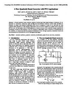
1756-ENBT 10.5.140.55
Programming Terminal 10.5.140.40
WAGO 750-841 10.5.140.50
Ethernet Switch SYSTEM CONFIGURATION NOTE: This procedure assumes that the WAGO 750-841 contains a valid IP address and it is installed on a working network, along with the Allen Bradley 1756-ENBT and the RSLogix5000 programming terminal. If necessary, refer to WAGO’s Application Note A202900 for assigning a static IP address to the WAGO 750-841.
Application note A203200
7
4 Solution Network variables are addressable memory inside the PFC where data can be shared between two or more networked devices. In distributed control systems, this area is used as a mailbox, for sharing status and control information between devices. The figure below illustrates the data exchange between the ControlLogix PLC and the network variables of the WAGO PFC. There are 256 words of EtherNet/IP network variables in both the input and output process image of the 750-841. In this application note, 10 registers of integer data will be configured for exchange in the input and output process image of both devices.
There are three main steps to configure this system: 1) Enable the 750-841 PFC for EtherNet/IP Communications 2) Configure the EtherNet/IP Assembly Object in the 750-841 PFC 3) Configure the 1756-ENBT as an Ethernet/IP Scanner
Application note A203200
8
4.1 Enable the 750-841 PFC for EtherNet/IP Communications The Ethernet/IP protocol is not recognized by default by the 750-841 Ethernet Controller, so it is necessary to enable this protocol. This is done using a browser to access the internal webpages of the 750-841. To enable the 750-841 for Ethernet/IP communications using a browser: 1) Run the browser utility (e.g. Microsoft’s Internet Explorer) on the programming terminal.
2) In the address bar, enter the IP address of the 750-841 Ethernet Controller, and hit Enter. The 750-841’s internal webpage should appear. If it does not appear, check that you have an Ethernet link to the 750-841’s Ethernet port, and the IP address of the programming terminal is compatible with the IP address of the 750-841. 3) Click ‘Port’ in the left browser frame. The following will appear:
4) Enter the following: User Name:admin Password: wago Click OK. The ‘Port configuration’ frame will appear. 5) In this frame, you must check ‘Ethernet IP’ as enabled. You may enable or disable other protocols at this time as well. Click ‘SUBMIT’ when finished. Perform a hardware or software reset so the new settings take effect. The WAGO 750-841 Ethernet Controller is now enabled for Ethernet/IP communications.
Application note A203200
9
4.2 Configure the EtherNet/IP Assembly Object in the 750-841 The EtherNet/IP assembly class is used to bind attributes of multiple objects to create a single assembly, which can be sent/received over a single connection. The size of the assembly object must be the same in both the producing and consuming device for successful implicit communication. The 750-841 uses its coupler configuration object (class 16#64) to configure the size of the assembly when PFC network variables are included in the object. The following 4-rung program illustrates how to configure the size of the assembly object (Class 4, Instance 16#6E and instance 16#6F) in the PFC using WAGO’s EML_UCMM_REQ function block. This function block is part of the EML.LIB library, and is capable of sending unconnected Ethernet/IP messages. In addition to sending messages to other devices on the network, this function block can be used to access Ethernet/IP objects inside the local PFC. When accessing objects inside the local PFC, an IP address of 127.0.0.1 is used. This address is the loop back address of the device being programmed. In this example, the EML_UCMM_REQ function block will be used to configure the local objects Bk_FbInp_PlcOnly_Var_Cnt (Class 16#64, Attribute16#66) and Bk_FbOut_PlcOnly_Var_Cnt (Class 16#64, Attribute16#68) of the configuration class (class 16#64). Please refer to page 185 of the 750-841 Instruction Manual for further details on the configuration class and attributes.
WAGO-I/O-PRO CAA - Declaration Window
Application note A203200
10
WAGO-I/O-PRO CAA – Rungs 1 and 2
Application note A203200
11
WAGO-I/O-PRO CAA – Rungs 3 and 4
After the above program is loaded and run on the 750-841 PFC, the size of instances 16#6E and 16#6F of the assembly class (16#04) are set to 20 bytes (10 integers). The size of theses objects are stored in non-volatile memory and are retained during power loss and program downloads. The WAGO 750-841 PFC is now configured for 10 integers of input and output EtherNet/IP network data.
Application note A203200
12
4.3 Configure the 1756-ENBT as an Ethernet/IP Scanner This section assumes that you have an overall understanding of Allen Bradley’s hardware and software. It focuses only on configuring the Logix5555 controller with RSLogix5000, so the WAGO PFC network variables are accessible via Ethernet/IP. 1) Start RSLogix5000. The RSLogix5000 main window is displayed.
Application note A203200
13
2) Create a new project with RSLogix5000. Select the File…New menu item. The New Controller dialog window is displayed.
3) Enter the following parameters: Type: Revision Name Description Chassis Type Slot Created In:
1756-L55 ControlLogix5555 Controller 12 WAGO_EtherNetIP_PFC_Vars Enter an appropriate description 1756-A4 4-Slot ControlLogix Chassis 0 Enter the appropriate directory
4) Click on OK.
Application note A203200
14
5) Before adding the WAGO I/O to the Logix5555 I/O configuration, you must first add the local 1756-ENBT module. To do this, open the I/O Configuration folder in the project window. Right click on I/O Configuration and select the New Module menu item.
The Select Module Type dialog window is displayed.
6) Select 1756-ENBT/A … from the list and click OK. Application note A203200
15
The Module Properties... dialog window is displayed.
7) Enter the following parameters: Name: IP Address: example) Slot: Electronic Keying
Local_ENBT 10.5.140.55
(IP Address of the 1756-ENBT in this
1 (slot of the controller) Compatible Module
8) Click the Finish button. The module will appear in the I/O Configuration. 9) Right click on 1756-ENBT/A Local_ENBT tree item, and select the New Module… menu item.
Application note A203200
16
The Select Module Type dialog window is displayed.
10) Select Generic Ethernet Module from the list and click OK.
Application note A203200
17
The Module Properties… dialog window is displayed.
11) Enter the following parameters: Name: Comm Format: IP Address Input Assembly Instance Input Size Output Assembly Instance Output Size Configuration Assembly Instance Configuration Size
Application note A203200
WAGO_IO Data – INT 10.5.140.50 110 10 111 10 1 0
(16-bit signed integer; -32768 to +32767) (IP Address of WAGO 750-841) (CIP Assembly Instance) (10 Integers of Input Network Data) (CIP Assembly Instance) (10 Integers of Output Network Data) (Not used by system) (Not used by system)
18
12) The program/configuration can now be downloaded to the Logix5555 controller. Select the Communications…Download program menu item. After downloading, if everything was setup correctly, the “I/O OK” indicator should be solid green. Additionally, when the cursor is placed on the ETHERNET-MODULE WAGO_Node1, the Module Fault box at the bottom of the figure below should be blank, indicating no error.
If an error does occur, the screen will look similar to the one below. This error is indicating an improper connection size was entered for either the input or output parameters.
Application note A203200
19
13) To view the process data from the WAGO 750-841, click on the Controller Tags tree item.
The Controller Tags dialog window opens. In this example only data from the WAGO 750-841 is displayed. In a real world application, more data would be included in the project.
Application note A203200
20
14) Click the + button to expand the Controller Tags view.
Application note A203200
21
After completing these steps, the configuration of the WAGO 750-841 PFC and the1756ENBT Ethernet/IP Scanner are complete. The PFC Input and Output Network data is now accessible to the Logix5555 controller as defined in the tables below: RSLogix Input Data RSLogix Variable WAGO_Node1:I.Data[0] WAGO_Node1:I.Data[1] WAGO_Node1:I.Data[2] WAGO_Node1:I.Data[3] WAGO_Node1:I.Data[4] WAGO_Node1:I.Data[5] WAGO_Node1:I.Data[6] WAGO_Node1:I.Data[7] WAGO_Node1:I.Data[8] WAGO_Node1:I.Data[9]
WAGO IEC61131-3 Address %QW1276 %QW1277 %QW1278 %QW1279 %QW1280 %QW1281 %QW1282 %QW1283 %QW1284 %QW1285
RSLogix Output Data RSLogix Variable WAGO_Node1:O.Data[0] WAGO_Node1:O.Data[1] WAGO_Node1:O.Data[2] WAGO_Node1:O.Data[3] WAGO_Node1:O.Data[4] WAGO_Node1:O.Data[5] WAGO_Node1:O.Data[6] WAGO_Node1:O.Data[7] WAGO_Node1:O.Data[8] WAGO_Node1:O.Data[9]
WAGO IEC61131-3 Address %IW1276 %IW1277 %IW1278 %IW1279 %IW1280 %IW1281 %IW1282 %IW1283 %IW1284 %IW1285
RSLogix Configuration Data The configuration data (e.g., WAGO_Node1:C.Data[0]) is automatically assigned by RSLogix when a Generic Ethernet/IP module is added as I/O. Since the WAGO 750-841 does not use this data, it should be ignored.
Application note A203200
WAGO Kontakttechnik GmbH Postfach 2880 • D-32385 Minden Hansastraße 27 • D-32423 Minden Phone: 05 71/8 87 – 0 Telefax: 05 71/8 87 – 1 69 E-Mail:
[email protected] Internet:
http://www.wago.com