built-in testing of such circuits for testing delay and stuck-open faults. .... A three-stage accumulator consisting of a carry-free adder ..... 'Additive cellular automata theory and applications' (IEEE Computer. Society Press, Los Alamitos, CA, 1997), vol. 1. 10 Nandi, S., Vamsi, B., Chakraborty, S., and Pal Chaudhuri, P.: 'Cellular.
Accumulator-based built-in self-test generator for robustly detectable sequential fault testing I. Voyiatzis, N. Kranitis, D. Gizopoulos, A. Paschalis and C. Halatsis Abstract: In this paper an algorithm for the generation of single input change (SIC) pairs is presented, termed the accumulator-based SIC pair generation (ASG) algorithm; SIC pairs have been effectively utilised for testing robustly detectable sequential faults. ASG is implemented in hardware utilising an accumulator whose inputs are driven by a barrel shifter. Since such structures (accumulators whose inputs are driven by barrel shifters) are commonly found in current, highspeed signal processing VLSI circuits, the presented schema provides a practical solution for the built-in testing of such circuits for testing delay and stuck-open faults. Utilisation of ASG to applying SIC pairs to adjacent pairs of inputs of the CUT, resulting in pseudoexhaustive schemes, is also addressed.
1
Introduction
In current IC technology, where highly complex chips have low accessibility of internal nodes, traditional testing becomes costly and ineffective; built-in self test (BIST) techniques have been proposed as an efficient alternative to external testing. BIST employs on-chip test generation and response verification; thereby the need for expensive external testing equipment is greatly reduced. Furthermore, with BIST at-speed testing can be achieved and the quality of the delivered ICs is highly increased [1]. Exhaustive testing provides 100% fault coverage of detectable single and multiple stuck-at faults without the need for fault simulation or deterministic test pattern generation. However, a large class of physical defects do not map into these fault categories. A transistor stuck-open fault in a CMOS circuit can convert a combinational Circuit Under Test (CUT) into a sequential one [2]. On the other hand, a delay fault does not affect the steady-state operation, but may cause circuit malfunction at clock speed [3, 4]. Detection of such faults requires two-pattern tests. In the literature, several two-pattern BIST generators have been presented, e.g. [5 –14]. Dufaza and Zorian [5] devised algorithms to generate deterministic two-pattern tests utilising LFSRs. Craig [6], Wang [7], and Girard [8] presented BIST techniques to detect an important class of path delay faults, called robustly detectable faults [6]. In [9, 10] two-pattern test generation using cellular automata was investigated. Two largely known types of pairs of patterns have been investigated in the literature, Multiple Input Change (MIC) pairs and Single Input Change (SIC) pairs.
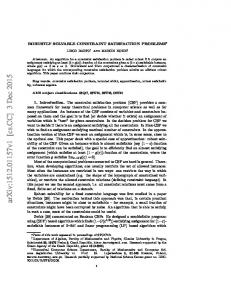
SIC pairs are pairs of patterns in which the first pattern of the pair differs from the second in exactly one bit. In the literature, it has been shown that SIC pairs hold some very interesting properties, thus a number of techniques have been presented for the generation of SIC pairs in a BIST environment e.g. [6 – 8, 11, 15– 22]. In Section 2, the particular usefulness of SIC pairs for the detection of delay faults is discussed and justified. Accumulators commonly exist in current VLSI circuits, e.g. in data path architectures, or in Digital Signal Processing chips, [23, 24]. Utilising accumulators for Built-In Testing (compression of the CUT responses [25 –28], or generation of test patterns [29 – 32]) results in low hardware overhead and low impact on the circuit normal operating speed. However, the techniques that have been presented in the literature target either the detection of stuck-at faults [29 – 31], or the generation of MIC twopattern tests [32], hence they are not suitable for the generation of SIC pairs. Pseudo-exhaustive testing has been widely accepted as a means of decreasing the number of test patterns required for the testing of combinational CUTs [29]. The problem of generating pseudo-exhaustive test patterns has been widely investigated, e.g. [33 –35]. However, pseudo-exhaustive testing for two pattern tests has been addressed only for the generation of Multiple Input Change pairs [36]. In this paper a technique is presented for the generation of SIC pairs of patterns, termed Accumulator-based SIC pair Generation (ASG). ASG is implemented in hardware utilising an accumulator whose inputs are driven by a barrel shifter. Such structures are commonly found in typical DSP cores (Fig. 1). Pseudo-exhaustive generation of SIC pairs is also addressed.
q IEE, 2004 IEE Proceedings online no. 20040850
2
doi: 10.1049/ip-cdt:20040850
SIC pairs are pairs of patterns in which the first pattern differs from the second in exactly one bit. The utilization of SIC pairs for the detection of stuck-open and delay faults holds some very interesting properties and has been approached by a number of researchers both theoretically [37] and experimentally [4, 15 –22]. In the theoretical field,
Paper first received 2nd April and in revised form 18th June 2004 I. Voyiatzis, N. Kranitis, A. Paschalis and C. Halatsis are with the Department of Informatics, University of Athens, Greece D. Gizopoulos is with the Department of Informatics, University of Piraeus, Greece 466
SIC pairs for two-pattern testing
IEE Proc.-Comput. Digit. Tech., Vol. 151, No. 6, November 2004
The above-referenced results, as well as a number of related works [15 – 22] indicate that the utilisation of SIC pairs in testing for delay and stuck-open faults compares favorably to the utilisation of MIC pairs, since it results in higher fault coverage with fewer test vectors. Hence, the generation of SIC pairs will be considered in the sequel. 3
Fig. 1 Typical datapath core
Smith [37] proved that SIC tests are sufficient to detect all robustly detectable path delay faults. In the experimental field, Wang and Gupta [7] proved that SIC pairs provide higher pseudorandom robust path delay fault coverage than MIC pairs. In other words, if a certain number of pairs is applied to the inputs of a Circuit Under Test (CUT), the achieved fault coverage is higher if the pairs are SIC, than if the pairs are MIC. For example, Table 1, obtained from [7], presents the delay fault coverage of robustly detectable faults obtained by applying 128K patterns to some of the ISCAS’89 benchmarks. Furthermore, the utilisation of SIC pairs for detecting non-robust faults has been studied. Table 2, obtained from [4], presents, for various ISCAS 89 benchmarks, the delay fault coverage of non-robust faults achieved by applying various number of patterns. The second column presents the nonrobust fault coverage obtained from an ATPG tool provided by Synopsys [38]. Table 1: Robust path delay fault coverage of MIC and SIC pairs (128K patterns)
Algorithm and hardware implementation
For the presentation, let V be an n-bit binary vector denoted with the low-order bit first, i.e. V ¼ v0 v1 . . . vn�1 : We shall denote with Vi the binary vector that differs from V in the i-th bit ð0 � i � n � 1Þ: For example, if V ¼ f010g; then V0 ¼ f110g; V1 ¼ f000g; V2 ¼ f011g: The ASG algorithm is presented in Fig. 2. It is trivial to prove that ASG generates all SIC pairs of n-bit vectors. The implementation of ASG is based on an accumulator whose inputs are driven by a barrel shifter. An accumulator consists of a register whose input is driven by a binary adder; the one input of the adder is the input of the accumulator whilst its other input is the output of the register (Fig. 3a). To implement ASG, the accumulator (more precisely, the adder of the accumulator) is modified as presented in Fig. 3b; we shall refer to the design of the modified adder with the term S-adder. We shall present the implementation in three steps: 1. Modification on the accumulator. Two cases will be considered: for an accumulator based (a) on a ripple-carry adder and (b) on a carry look ahead adder 2. Implementation and functionality of ASG utilising an accumulator whose inputs are driven from the outputs of a barrel shifter. 3. Calculation of the hardware overhead of modifications.
3.1 Modifications on the accumulator
fault coverage % Circuit
MIC
SIC
s208
87.2
100
s298
74.2
74.2
s344
84.8
86.1
s349
82.5
83.7
s420
60.8
69.1
s444
52.4
54.8
s510
98.6
98.8
s526
75.6
80.7
s820
86.5
95.4
s832
84.5
93.0
s1488
92.3
97.5
Table 2: Nonrobust path delay fault coverage of MIC and SIC pairs
A three-stage accumulator consisting of a carry-free adder and a register is presented in Fig. 3a. It takes as inputs a signal input So[0:2], a carry-in signal cin and a clock input, clk. The outputs of the accumulator are a carry-out signal cout ; and a signal output A[0:2]. To implement ASG, the adder of the accumulator is substituted by a module called S-adder, presented in Fig. 3b.
Fig. 2 ASG algorithm
fault coverage % Circuit
ATPG fc %
#patterns
MIC
SIC
s298
78, 79
68800
70.05
100
s382
91, 75
139800
79.42
100
s420
100
132200
61.29
s510
100
136600
71.14
s526
87, 80
139600
74.03
97.64
s641
71, 02
277800
81.55
82.72
s713
37, 13
441800
84.41
87.83
Fig. 3 ASG design
s1238
62, 93
499200
70.32
93.55
a Accumulator b Accumulator for ASG
IEE Proc.-Comput. Digit. Tech., Vol. 151, No. 6, November 2004
66.22 100
467
An S-adder module differs from a binary adder in that it has an additional input BISTeff and operates as follows: . when BISTeff ¼ 0; the S-adder operates as an ordinary
adder. . when BISTeff ¼ 1; the S-adder operates as a series of n
two – input XOR gates, i.e. each output of the S-adder is the eXclusive-OR of the corresponding inputs. In the sequel, two implementations of the S-adder will be presented, based on: (a) a ripple carry and (b) a carrylookahead implementation of the original adder.
3.1.1 Ripple carry implementation of the S-adder: The ripple carry implementation of the binary adder is presented in Fig. 4a. In Fig. 4b a NAND-XOR implementation of the Full Adder cell is presented. To implement the S-adder, the Full Adder cell is substituted by a cell termed ‘SIC Full Adder cell’ (SFA cell), presented in Fig. 5a. The resulting Adder is presented in Fig. 5b. The SFA cell takes an extra input, BISTeff; When BISTeff ¼ 0; the SFA cell operates identically to the full adder cell. When BISTeff ¼ 1; cin does not affect the S operation, and S ¼ A � B: The hardware overhead of the S-adder over the ordinary adder is n AND gates (n is the number of the stages of the adder). The modification has no impact on the timing
Fig. 4
Implementation of the S-adder
a Ripple carry adder b Full adder cell
Fig. 5
S-adder implementation and operation
a SFA cell b S-adder
Fig. 6
characteristics of the cell, since no gate is inserted in the path of the most critical path of the cell (the path that calculates the signal cout).
3.1.2 Carry-lookahead implementation of the S-adder: Again we start from the implementation of the original carry-lookahead adder presented in Fig. 6a [39]. The respective S-adder is presented in Fig. 6b. In Fig. 6b, an additional 2-input AND gate has been added to the signal cin ; also, an additional input has been added to the two-input gates that generate the signals Gi. The additional input is driven by the signal BISTeff. The carry-lookahead S-adder operates as follows: when BISTeff ¼ 1; Gi ¼ 0 (for all i) and Si ¼ Pi. Therefore, Si ¼ Ai � Bi for all i, 0 � i < 3:
3.2 Implementation of ASG The implementation of ASG is presented in Fig. 7. As has been stated, to implement ASG, an n-stage accumulator comprising an S-adder is utilised, whose inputs are driven by a barrel shifter. The shift inputs s½0� ; s½1� ; . . . s½k�1� ðk ¼ dlog2 neÞ of the shifter are driven by the k middle outputs of a ðk þ 2Þ-stage counter (all outputs excluding c[0] and c½k þ 1�) as presented in Fig. 7. The counter counts modulo 2n þ 1: The module presented in Fig. 7 operates as follows. The constant vector Si½0 : n � 1� ¼ f10 . . . 00g is driven into the data inputs of the shifter. Initially, all the outputs of the Accumulator A½0�; A½1�; . . . A½n � 1� are set to 0. The outputs of the modulo 2n þ 1 counter (excluding the low and the high-order output) are driven to the shift control inputs s½0� ; . . . ; s½k�1� of the shifter. The counter is initially set to 0 and increments by 1 in every clock cycle. During clock cycles 1; 3; 5; . . . 2n þ 1 the output of the accumulator is 00 . . . 00: During clock cycles 2; 4; 6; . . . 2n; the output of the accumulator is a (new) vector that differs from 00 . . . 00 in exactly one bit. In this way, all SIC pairs of 00 . . . 00 are generated. At cycle 2n þ 1; the output of the module named ‘detect 2n’ (an AND gate that detects the value 2n at the outputs of the counter) is ‘1’, therefore, in the next clock cycle the signal BISTeff is disabled (for one clock cycle); thus, the accumulator adds its previous (all-zero) value to the output of the shifter, and the value ‘10 . . . 00’ is generated at the output of the accumulator. From now on, BISTeff is enabled and the generation of all SIC pairs of 10 . . . 00 begins. After the generation of all SIC pairs of 10 . . . 00 to the outputs of the accumulator, the signal BISTeff is disabled for one clock cycle, the accumulator accumulates 100 . . . 00 to 10 . . . 00
Carry-lookahead implementation
a Three-bit adder b Respective S-adder 468
IEE Proc.-Comput. Digit. Tech., Vol. 151, No. 6, November 2004
Table 3: Operation of 4-stage ASG #cycle
Fig. 7 n-stage ASG implementation
Fig. 8 Implementation of a four-stage ASG
(the output of the shifter) and the vector 010 . . . 00 is generated at the outputs of the accumulator. Every time the SIC pairs of a pattern are generated, the signal BISTeff is disabled, and another pattern is generated at the outputs of the accumulator. An implementation of a four-stage generator is presented in Fig. 8. The operation of the module of Fig. 8 is presented in Table 3. In Table 3 the first column presents the number of the cycle; the second column presents the output of the counter; the third column presents the s½i� inputs of the shifter, the fourth column presents the output of the shifter and the fifth column the output of the accumulator. The next value of the accumulator is calculated as the bit-by-bit exclusive-or of the current value of the accumulator and the current value of the shifter. At clock cycle 9, BISTeff is disabled, the accumulator operates normally, and the pattern 1000 is generated at the outputs of the accumulator. The same holds for clock cycles 18; 27; . . . 135:
3.3 Calculation of the hardware overhead To calculate the hardware overhead of ASG let n denote the number of the stages of the accumulator-shifter. We shall calculate the hardware overhead for both a ripple-carry and a carry-lookahead implementation of the adder.
counter[3:0]
s[1:0]
So[0:3]
A[0:3]
1
0000
00
1000
0000
2
0001
00
1000
1000
3
0010
01
0100
0000
4
0011
01
0100
0100
5
0100
10
0010
0000
6
0101
10
0010
0010
7
0110
11
0001
0000
8
0111
11
0001
0001
9
1000
00
1000
0000
10
0000
00
1000
1000
11
0001
00
1000
0000
12
0010
01
0100
1000
13
0011
01
0100
1100
14
0100
10
0010
1000
15
0101
10
0010
1010
16
0110
11
0001
1000
17
0111
11
0001
1001
18
1000
00
1000
1000
19
0000
00
1000
0100
20
0001
00
1000
1100
21
0010
01
0100
0100
22
0011
01
0100
0000
23
0100
10
0010
0100
24
0101
10
0010
0110
25
0110
11
0001
0100
26
0111
11
0001
0101
27
1000
00
1000
0100
...
...
...
...
...
127
0000
00
1000
1111
128
0001
00
1000
0111
129
0010
01
0100
1111
130
0011
01
0100
1011
131
0100
10
0010
1111
132
0101
10
0010
1101
133
0110
11
0001
1111
134
0111
11
0001
1110
135
1000
00
1000
1111
136
0000
00
1000
1111
137
0001
00
1000
0111
138
0010
01
0100
1111
139
0011
01
0100
1011
140
0100
10
0010
1111
141
0101
10
0010
1101
142
0110
11
0001
1111
143
0111
11
0001
1110
144
1000
00
1000
1111
(a) ripple-carry implementation of the adder In this case, the following components are implemented: (i) n 2-input AND gates for the SFA cell. The overhead of each two-input AND gate is [40] 6 transistors. (ii) the counter that drives the shift control inputs of the shifter. The number of the stages of the counter is dlog2 ne þ 2: For each stage of the counter, a D-type flip-flop IEE Proc.-Comput. Digit. Tech., Vol. 151, No. 6, November 2004
and few gates are required. The hardware overhead of a D-flip flop is 26 transistors. The hardware overhead of the combinational part of each stage is 10 transistors [40]. Therefore, the hardware overhead is 36ðdlog2 ne þ 2Þ: As a whole, the hardware overhead of ASG (in transistors) is 6n þ 36ðdlog2 ne þ 2Þ: It is noteworthy that this is the only 469
hardware overhead required, and no other control logic is needed for the generation of the SIC pairs. (b) Carry-lookahead implementation of the adder In this case, the following components are implemented: (i) one 2-input AND gate is added (in cin ) and (ii) the number of inputs of the AND gates generating Gi (Figs. 6a and 6b) increases from two to three. Therefore, the hardware overhead because of the AND gates is approximately 2n þ 2 [23]. As a whole, the overall hardware overhead (including the counter) is 2ðn þ 1Þ þ 36ðdlog2 ne þ 2Þ: 4
Comparisons
In this Section ASG will be compared with the techniques proposed hitherto for the generation of SIC pairs [6 –8, 11], in terms of hardware overhead and time required to generate the SIC pairs. For the comparisons, we shall assume that (a) an n-stage register (consisting of n flip flops) exists at the inputs of the n-input CUT for the case of [6 – 8, 11], and we shall calculate the overhead imposed on these flip-flops. For the case of ASG we shall assume the existence of the accumulator whose inputs are driven by a barrel shifter. In Peat [6], an n-stage NFSR, an n-stage shift register and an n-stage shift registers with flip capability are utilized to generate the SIC pairs within ðn þ 1Þ � 2n clock cycles. To implement the technique the NFSR and n scan flip-flops with flip capability are implemented. Furthermore, the n flip flops of the existing register are substituted by scan flipflops. Wang and Gupta [7] utilised a ð2n þ 1Þ-stage shift register, an n-stage LFSR and n 2-input XOR gates in order to generate the n-bit SIC pairs within n � 2nþ1 clock cycles. Thereby, 2n þ 1 scan flip-flops and n 2-input XOR gates are implemented. Girard et al. [8] proposed an optimisation of [6] that saves n stages of the shift register substituting them with n 2-input And gates. The time required to generate the SIC pairs is the same as in [6]. In [11] a different approach was presented that utilises an ðn � 1Þ-stage counter, an n-stage shift register and a series of n 2-input XOR gates to generate the SIC pairs within ðn þ 1=2Þ � 2n clock cycles. The hardware overhead of the technique is n flip flops and n 2-input XOR gates. ASG requires the transformation of the adder to an S-Adder; it also requires the implementation of the counter whose inputs drive the shift control inputs of the shifter; the time required to generate the SIC pairs is ð2n þ 1Þ � 2n : It should be noted that the ASG solution is favoured only if
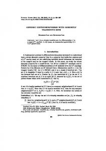
accumulators and barrel shifters are available (which is not the case for most of the other approaches). For the comparisons the following are taken into account [40]. A two-input NAND=NOR gate requires four transistors; a two-input AND requires six transistors and a twoinput XOR gate can be implemented by six CMOS transistors using transmission gates. The memory elements used are considered to have set=reset capability. Thereby, the flip-flop requires 26 transistors, the scan flip-flop requires 34 transistors and the scan flip-flop with flip capability [6] requires 46 transistors. All techniques, except from ASG, require that the n flip-flops at the inputs of the Cut be transformed into scan flip flops. In Table 4 we present, for each one of the SIC pair generation techniques (first column) the time required to generate the SIC pairs (in clock cycles, second column) the formulas used for the calculation of the hardware overhead (third column) and the hardware overhead (in transistors, fourth column). To perform a quantitative comparison of the techniques, we define the following metrics. Let SG can be any one of the techniques proposed in [6 – 8, 11] and ASG. Let hon ðSGÞ denote the hardware overhead of SG and tn ðSGÞ denote the time required by SG to generate all n-bit SIC pairs. Since the hardware overhead is of the order O(n), we define the effective hardware overhead, e hon ðSGÞ as a metric of the hardware overhead as follows. e hon ðSGÞ ¼
hon ðSGÞ n
Similarly, since the time in clock cycles is of the order Oðn � 2n Þ we define the effective time, e tn ðSGÞ as follows: e tn ðSGÞ ¼
logðtn ðSGÞÞ n
We integrate the above two metrics into the effectiveness En ðSGÞ defined as follows: En ðSGÞ ¼
1 1 ¼ ho ðSGÞ logðt ðSGÞÞ n n e hon ðSGÞ � e tn ðSGÞ � n
n
n2 ¼ hon ðSGÞ � logðtn ðSGÞÞ Since it is desirable that both hon ðSGÞ and tn ðSGÞ be as low as possible, the higher the value of En ðSGÞ; the more effective is SG. In Fig. 9, En ðSGÞ is presented for each one of the techniques for various values of the inputs of the Cut. From Fig. 9 it is derived that Asg is the most effective of the techniques that have been presented in the literature for the generation of SIC pairs with respect to the hardware overhead and the time required to complete the test.
Table 4: SIC pair generation techniques: comparison Hardware overhead Technique
Time (cycles)
Modules
Transistors
PEAT [5]
ðn þ 1Þ � 2n
n � ðDFF þ NORÞ þ n � DFFscanwithflip þ n � ðDFFscan � DFFÞ
84 � n
WANG [6]
2n � 2n
ð2n þ 1Þ � DFF þ n � XOR þ n � ðDFFscan � DFFÞ
66 � n þ 26
GIRARD [7]
2n � 2n
ðn þ 1Þ � DFF þ n � AND þ n � XOR þ n � ðDFFscan � DFFÞ
42 � n
VOYIATZIS [10]
ðn þ 1=2Þ � 2n
n � DFF þ n � XOR þ n � ðDFFscan � DFFÞ
40 � n
ASG (RIPPLE CARRY ADDER)
ð2n þ 2Þ � 2n
n � AND þ 2 � DFF þ n � MUX þ AND þ OR
12n þ 65
ASG (CARRY LOOKAHEAD ADDER)
ð2n þ 2Þ � 2n
1 � AND þ n � ðAND3 � AND2 Þ þ 2 � DFF þ n � MUX
8n þ 65
þ AND þ OR 470
IEE Proc.-Comput. Digit. Tech., Vol. 151, No. 6, November 2004
Table 5: Operation of (9,3)-pseudoexhaustive ASG counter
Fig. 9 SIC pair generation: comparison
5
Pseudo-exhaustive SIC generation
Pseudo-exhaustive testing has been widely recognised as a means of driving down the number of vectors needed to complete a test. Adjacent bit (n, m)-pseudo-exhaustive testing, from now on referred to as (n, m)-pseudo-exhaustive testing for simplicity, applies all input combinations to all consecutive m-bit groups of inputs of the CUT [28] as shown in Fig. 10. Pseudo-exhaustive adjacent bit testing is suitable for datapath modules where adjacent input lines drive internally adjacent lines (e.g. bit-slice structures) [29]. For the case of SIC generation, (n, m)-pseudo-exhaustive testing applies all m � 2m combinations to all consecutive m-bit groups of inputs of the CUT. To perform (n, m)-pseudo-exhaustive generation based on ASG, the ASG generator is modified as follows: vector 100 . . . 0100 . . . 0 . . . : with the form f1f0gm�1 gdn=me is applied to the inputs of the barrel shifter
. The
Fig. 10 (9, 3)-Pseudo-exhaustive adjacent-bit testing
s[1:0]
So[0:8]
#cycle [3:0]
0:2
3:5
6:8
A[0:8] 0:2
3:5
6:8
1
0000
00
100
100
100
000
000
000
2
0001
00
100
100
100
100
100
100
3
0010
01
010
010
010
000
000
000
4
0011
01
010
010
010
010
010
010
5
0100
10
001
001
001
000
000
000
6
0101
10
001
001
001
001
001
001
7
0110
11
100
100
100
000
000
000
8
0000
00
100
100
100
100
100
100
9
0001
00
100
100
100
000
000
000
10
0010
01
010
010
010
100
100
100
11
0011
01
010
010
010
110
110
110
12
0100
10
001
001
001
100
100
100
13
0101
10
001
001
001
101
101
101
14
0110
11
100
100
100
100
100
100
15
0000
00
100
100
100
010
010
010
16
0001
00
100
100
100
110
110
110
17
0010
01
010
010
010
010
010
010
18
0011
01
010
010
010
000
000
000
19
0100
10
001
001
001
010
010
010
20
0101
10
001
001
001
011
011
011
21
0110
11
100
100
100
010
010
010
22
0000
00
100
100
100
110
110
110
23
0001
00
100
100
100
010
010
010
24
0010
01
010
010
010
110
110
110
25
0011
01
010
010
010
100
100
100
26
0100
10
001
001
001
110
110
110
27
0101
10
001
001
001
111
111
111
28
0110
11
100
100
100
110
110
110
29
0000
00
100
100
100
001
001
001
30
0001
00
100
100
100
101
101
101
31
0010
01
010
010
010
001
001
001
32
0011
01
010
010
010
011
011
011
33
0100
10
001
001
001
001
001
001
34
0101
10
001
001
001
000
000
000
35
0110
11
100
100
100
001
001
001
36
0000
00
100
100
100
101
101
101
37
0001
00
100
100
100
001
001
001
38
0010
01
010
010
010
101
101
101
39
0011
01
010
010
010
111
111
111
40
0100
10
001
001
001
101
101
101
41
0101
10
001
001
001
100
100
100
42
0110
11
100
100
100
101
101
101
43
0000
00
100
100
100
011
011
011
44
0001
00
100
100
100
111
111
111
45
0010
01
010
010
010
011
011
011
46
0011
01
010
010
010
001
001
001
47
0100
10
001
001
001
011
011
011
48
0101
10
001
001
001
010
010
010
49
0110
11
100
100
100
011
011
011
50
0000
00
100
100
100
111
111
111
51
0001
00
100
100
100
011
011
011
52
0010
01
010
010
010
111
111
111
53
0011
01
010
010
010
101
101
101
54
0100
10
001
001
001
111
111
111
55
0101
10
001
001
001
110
110
110
56
0110
11
100
100
100
111
111
111
Fig. 11 ASG (9, 3)-pseudo-exhaustive generator IEE Proc.-Comput. Digit. Tech., Vol. 151, No. 6, November 2004
471
. A k þ 2 bit counter, where k ¼ dlog2 me is utilised, whose
k middle inputs drive the k low-order shift inputs of the barrel shifter. . The BISTeff signal is calculated by the 2m-detect module. In Fig. 11 the (9, 3)-SIC pseudoexhaustive generator is presented, and in Table 5 its operation is illustrated. From Table 5 it is evident that all 3 � 23 SIC combinations are applied to all triplets of adjacent inputs. 6
Conclusions
In this paper a technique for the generation of SIC twopattern tests has been presented, termed Accumulator-based SIC pair Generation (ASG) algorithm. ASG can be implemented in hardware utilising an accumulator whose inputs are driven by a barrel shifter. Comparisons with the techniques that have been proposed in the literature for the generation of SIC pairs [6 – 8, 11], revealed that Asg is more effective in terms of hardware overhead and time required to generate the SIC pairs when accumulators and barrel shifters are available. Another point to observe is that the delay overhead is (a) one AND gate in case that the accumulator is implemented utilising a carry-lookahead adder, or (b) no delay in case the accumulator is implemented utilising a ripple carry adder. Last, but not least, ASG can be easily modified, to exercise pseudo-exhaustive adjacent bit testing. To the best of our knowledge, this is the first technique proposed in the open literature for the generation of SIC pairs that can be easily adapted to the concept of pseudo-exhaustive testing. 7
References
1 Abramovici, M., Breuer, M., and Freidman, A.: ‘Digital systems testing and testable design’ (Computer Science Press, 1990) 2 Wadsack, R.L.: ‘Fault modeling and logic simulation of CMOS and MOS integrated circuits’, Bell Syst. Tech. J., 1987, 57, (5), pp. 1449–1474 3 Woods, M.H.: ‘MOS VSI Reliability and Yield Trends’. Proc. IEEE, 1986, 74, 12, pp. 1715–1729 4 Girard, P., Landrault, C., Pravossoudovitch, S., and Virazel, A.: ‘Comparison between random and pseudorandom generation for BIST of delay, stuck-at and bridging faults’. Proc. IEEE On-Line Testing Workshop, 2000, pp. 121–126 5 Dufaza, C., and Zorian, Y.: ‘On the generation of pseudo-deterministic two-pattern test sequences with LFSRs’. Proc. European Design and Test Conf., Paris, France, 17–20 March 1997, pp. 69 –76 6 Craig, G., and Kime, Ch.: ‘Pseudo-exhaustive adjacency testing: a BIST approach for stuck-open faults’. Proc. IEEE Int. Conf., 1985, pp. 126–137 7 Wang, W., and Gupta, S.: ‘Weighted random robust path delay testing of synthesized multilevel circuits’. Proc. IEEE VLSI Test Symp., 1994, pp. 291–297 8 Girard, P., Landrault, C., Moreda, V., and Pravossoudovitch, S.: ‘An optimized BIST test pattern generator for delay testing”. Proc. VLSI Test Symp., 1997, pp. 94 –100 9 Pal Caudhuri, P., Roy Chowdhury, D., Nandi, S., and Chattopadhay, S.: ‘Additive cellular automata theory and applications’ (IEEE Computer Society Press, Los Alamitos, CA, 1997), vol. 1 10 Nandi, S., Vamsi, B., Chakraborty, S., and Pal Chaudhuri, P.: ‘Cellular automata as a BIST structure for testing CMOS circuits’, IEE Proc.Comput. Digit. Tech., 1994, 141, (1), pp. 41–47 11 Voyiatzis, I., Paschalis, A., Nikolos, D., and Halatsis, C.: ‘An efficient built-in self test method for robust path delay fault testing’, J. Electron. Test. Theory Appl., June 1996, pp. 219–222
472
12 Starke, C.W.: ‘Built-in test for CMOS circuits’. Proc. IEEE Int. Test Conf., Oct. 1984, pp. 309–314 13 Vuksic, A., and Fuchs, K.: ‘A new BIST approach for delay fault testing’. Proc. European Design and Test Conf., March 1994, pp. 284– 288 14 Chen, Ch., and Gupta, S.K.: ‘BIST test pattern generators for stuckopen and delay testing’. Proc. European Design and Test Conf., March 1994, pp. 289–296 15 Virazel, A., David, R., Girard, P., Landrault, C., and Pravossoudovitch, S.: ‘Delay fault testing: choosing between random SIC and random MIC sequences’. Proc. IEEE European Test Workshop, 2000, pp. 9–14 16 Rahaman, H., Das, D., and Bhattacharya, B.: ‘Transition count based BIST for detecting multiple stuck-open faults in CMOS circuits’. Presented at 2nd IEEE Asia Pacific Conf. on ASICs, 28– 30 August 2000 17 Crepaux-Motte, Jacomino, M., and David, R.: ‘An algebraic method for delay testing’. 14th VLSI Test Symp., 1996, pp. 308 –315 18 Gharaybeh, M., Bushnell, M., and Agrawal, V.: ‘Parallel concurrent path delay fault simulation using single-input change patterns’. 9th IEEE Int. Conf. on VLSI Design, January 1996, pp. 426–431 19 Gharaybeh, M., Bushnell, M., and Agrawal, V.: ‘A parallel-vector concurrent fault simulator and generation of single-input-change tests for path-delay faults’. IEEE Trans. Comput.-Aided Des. Integr. Circuits Syst., 1998, 17, 9 20 Das, D., Chaudhuri, I., and Bhattacharya, B.: ‘Design of an optimal test pattern generator for built-in self testing of path delay faults’, Proc. VLSI, 1997, pp. 205 –210 21 Lu, S., and Lu, M.: ‘Testing iterative logic arrays for delay faults with a constant number of patterns’. Int. Symp. on Electronic Materials and Packaging, 2002, pp. 492–498 22 David, R., Girard, P., Landrault, C., Pravossoudovitch, S., and Virazel, A.: ‘On using efficient test sequences for BIST’. Presented at VLSI Test Symp., 2002 23 Blokken, E., de Keulenaer, H., Catthoor, F., and de Man, H.J.: ‘A flexible module library for custom DSP applications in a multiprocessor environment’, IEEE J. Solid-State Circuits, 1990, 25, (3), pp. 720–729 24 Higgins, R.J.: ‘Digital signal processing in VLSI’ (Prentice Hall, Englewood Cliffs, NJ, 1990) 25 Rajski, J., and Tyszer, J.: ‘Accumulator-based compaction of test responses’, IEEE Trans. Comput., 1993, 42, (6), pp. 643–650 26 Rajski, J., and Tyszer, J.: ‘Test responses compaction in accumulators with rotate carry adders’, IEEE Trans. Comp.-Aided Des. Integr. Circuits Syst., 1993, 12, (4), pp. 531 –539 27 Stroele, A.P.: ‘Test response compaction using arithmetic functions’. Proc. 14th VLSI Test Symp., 1996, pp. 380–386 28 Rasksi, J., and Tyszer, J.: ‘Arithmetic built-in self test for embedded systems’ (Prentice Hall, Upper Saddle River, NJ, 1998) 29 Gupta, S., Rajski, J., and Tyszer, J.: ‘Arithmetic additive generators of pseudo-exhaustive test patterns’, IEEE Trans. Comput., 1996, 45, (8), pp. 939– 949 30 Stroele, A.P.: ‘BIST pattern generators using addition and subtraction operations’, 1997, Jetta, 11, pp. 69 –80 31 Radecka, K., Rajski, J., and Tyszer, J.: ‘Arithmetic built-in self test for dsp cores’, IEEE Trans. Comput. Aided Des. Integr. Circuits Syst., 1997, 16, (11), pp. 1358– 1369 32 Voyiatzis, I., Paschalis, A., Nikolos, D., and Halatsis, C.: ‘Accumulator-based BIST approach for stuck-open and delay testing’. Proc. European Design and Test Conf., March 1995, pp. 431– 435 33 Rajski, J., and Tyszer, J.: ‘Recursive pseudoexhaustive test pattern generation’, IEEE Trans. Comput., 1993, 42, (12), pp. 1517–1521 34 Das, A.K., and Chaudhuri, P.P.: ‘Vector space theoretic analysis of additive cellular automata and its application for pseudo-exhaustive test pattern generation’, IEEE Trans. Comput., 1993, 42, (3), pp. 340 –352 35 Dasgupta, P., Chattopadhyay, S., Chaudhuri, P.P., and Sengupta, I.: ‘Cellular automata-based recursive pseudoexhaustive test pattern generation’, IEEE Trans. Comput., 2001, 50, (2), pp. 177–185 36 Voyiatzis, I., Paschalis, A., Nikolos, D., and Halatsis, C.: ‘Exhaustive and pseudoexhaustive built-in two-pattern generation for datapaths’. Presented at IEEE Int. On-Line Test Workshop, 1998 37 Smith, G.L.: ‘Model for delay faults based upon paths’. Proc. IEEE Int. Test Conf., 1984, pp. 309–314 38 TestGen: version TG3.0.2 User Guide, Synopsys Inc., 1999 39 Manot, M.: ‘Digital Design’ (Prentice Hall, 1991, 2nd ed.) 40 Weste, N., and Eshraghian, K.: ‘Principles of CMOS VLSI design: a systems perspective’ (Addison Wesley, 1985)
IEE Proc.-Comput. Digit. Tech., Vol. 151, No. 6, November 2004