Dec 8, 2000 - are non rational, see Reference [12], and the local basis can naturally contain terms which are solution of ..... Eng. 139:3-47, (1996). [12] Ph.
Accurate acoustic computations using a meshless method St´ephane Suleau∗
Philippe Bouillard∗
December 8, 2000
Abstract It is well known today that the standard finite element method (FEM) is unreliable to compute approximate solutions of the Helmholtz equation for high wavenumbers due to the pollution effect, consisting mainly of the dispersion, i.e. the numerical wavelength is longer than the exact one. Unless highly refined meshes are used, FEM solutions lead to unacceptable solutions in terms of precision. The paper presents an application of the Element-Free Galerkin Method (EFGM) leading to extremely accurate results in comparison with the FEM. Moreover, the present meshless formulation is not restricted to regular distribution of nodes as some stabilisation methods and a simple but real-life problem is investigated in order to show the improvement in the accuracy of the numerical results, as compared with FEM results.
1
Introduction
The numerical solution of the Helmholtz equation, governing the wave propagation, is one of the main problems that has not yet been properly addressed because of the spurious phenomena inherent to this differential operator. In one dimension, the solutions are oscillatory of type sin(kx) where k is the wavenumber. The major aspects of the numerical solution are the approximation error and the pollution effect. The discretization error can be split into the approximation error and the pollution error, [1] i.e. the error on the phase (dispersion error) and on the amplitude; for a summary of the pollution effect and demonstrations on industrial examples, see Reference [2]. The numerical wave is of dispersive character, i.e. the numerical wave propagates with a phase velocity ω/k h different from the speed of sound c; for a theoretical analysis for the finite element method, see e.g. Reference [3]. Several authors have suggested methods to stabilise the finite element method: the Galerkin Least Square (GLS) [5] consists of a modification of the variational problem in order to minimise the dispersion, ∗ Department
of Continuum Mechanics, Universit´ e Libre de Bruxelles, CP 194/5
Av. F. D. Roosevelt 50, 1050 Brussels, Belgium
1
the Quasi-Stabilised Finite Element Method (QSFEM) [6] modifies the system matrix with the same goal and more recently a Residual-Free Finite Element Method (RFFEM) [7] was implemented for the Helmholtz equation, etc. However, none of these methods eliminates the dispersion in a general two-dimensional case, see Reference [15] for a complete analysis. Nevertheless, most authors seem to agree that it is very advantageous to use a set of plane wave solutions of the homogenised Helmholtz equation as the local function basis. A natural and very efficient way to achieve this is to use a meshless formulation. I. Babuˇska and J. Melenk [8] suggest the partition of unity method while, in the present paper, the Element-Free Galerkin Method (EFGM) is investigated and seems particularly well suited for that purpose. The EFGM is based on the Moving Least Square Approximation (MLSA), first introduced by Lancaster et al. [9] in the field of surface and function smoothing. Recently, it has been extensively investigated by T. Belystchko et al. in the fields of elasticity and crack propagation problems [10, 11]. The main advantages of the formulation are well known, namely no connections by nodes and easy pre- and post-processing tasks. For the particular case of the Helmholtz equation, we also take advantage of the fact that the shape functions are non rational, see Reference [12], and the local basis can naturally contain terms which are solution of the Helmholtz equation. Our approach is closely related to the Trefftz approach, Reference [18], because the main feature of both approaches is the approximation of the solutions in terms of functions satisfying exactly the governing homogeneous equations. Very interesting results using a Trefftz approach for vibro-acoustic simulations have been reported in Reference [19]. Yet, our method has the additional advantage of being meshless. The paper is organised as follows. Sections 2 and 3 present the strong and variational forms of the acoustic problem. In section 4, the EFGM shape functions are defined and the method is applied to acoustics. Section 5 gives the definition of the dispersion error. Section 6 presents numerical results obtained with polynomial and frequency dependent function bases, the latter leading to the exact solution of the problem for some directions of propagation of a plane wave. Finally, tests on a 2D real-life problem are reported in Section 7 showing the improvement in terms of accuracy on the numerical solution.
2
STRONG FORMULATION OF THE ACOUSTIC PROBLEM
The topics described in sections 2 and 3 refer to strong and variational formulations of the harmonic forced response of the acoustic problem. They are recalls from Reference [16]. Consider the fluid inside a domain Ω with boundary Γ, let c be the speed of sound inside this medium and ρ the specific mass of the fluid. If p0 denotes the field of acoustic pressure (small perturbations around a steady uniform state), the equation of wave propagation (1) is derived from the fundamental equations of
2
continuum mechanics: ∆p0 =
1 ∂ 2 p0 c2 ∂t2
(1)
If the phenomena are assumed to be steady harmonic, p0 = p exp(jωt)
(2)
where ω is the angular frequency. The spatial distribution p of the acoustic pressure (which is a complex variable) inside Ω, is a solution of Helmholtz equation ∆p + k 2 p = 0
(3)
where the wavenumber k is defined by the ratio between the angular frequency and the speed of sound: k=
ω c
(4)
Another important quantity of the acoustic analysis is the particle velocity v linked to the gradient of the acoustic pressure through the equation of motion: jρckv + ∇p = 0
(5)
In order to completely define the acoustic problem, the Helmholtz equation (3) has to be associated with boundary conditions on Γ. The boundary is split into three parts Γ = ΓD ∪ ΓN ∪ ΓR
(6)
corresponding to different types of boundary conditions: • Dirichlet boundary conditions (the acoustic pressure is prescribed) p = p¯ on ΓD
(7)
• Neumann boundary conditions (the normal component of the velocity is prescribed) vn = v¯n or nt ∇p = −jρck¯ vn on ΓN
(8)
nt ∇p = −jρckAn p on ΓR
(9)
• Robin boundary conditions
where An is the admittance coefficient modelling the structural damping. Neumann boundary conditions correspond to vibrating panels while Robin boundary conditions correspond to absorbant panels. Conditions (7)-(9) have been defined for interior and exterior problems. For an infinite medium, the boundary condition at infinity is reduced by a DtN mapping on a fictitious sphere around the studied domain of the medium, leading to a boundary condition similar to (9). 3
3
VARIATIONAL FORMULATION OF THE ACOUSTIC PROBLEM
The variational formulation corresponding to the strong form presented in Section 2 is well known and in the following only the main aspects will be emphasised. For more details, see Reference [12]. The space of admissible trial functions p is defined as, © 1 HD (Ω) = p ∈ H 1 (Ω)
| p = p¯ on ΓD
ª
(10)
and the space of homogeneous test functions w is © H01 (Ω) = w ∈ H 1 (Ω) |
w = 0 on ΓD
ª
(11)
They are both subspaces of H 1 (Ω), the Sobolev space of functions square-integrable together with their first derivatives. We define the functional Π, Π= with
1 a (p, p˜) − ϕ (˜ p) 2 Z
a (p, p˜) :
1 HD
×
1 HD
→ ( | a (p, p˜) =
¡
¢ ∂i p ∂i p˜ − k p p˜ dΩ +
(12) Z
2
Ω
Z
1 ϕ (˜ p) : HD → ( | ϕ(˜ p) = −
j ρ c k An p p˜ dΓ
(13)
ΓR
j ρ c k v¯n p˜ dΓ
(14)
ΓN
where the notation ˜• stands for the complex conjugate. The variational form corresponding to the Helmholtz equation (3) and boundary conditions (7)-(9) is expressed by: 1 Find p ∈ HD | δΠ = 0 ∀δp ∈ H01
(15)
It is shown in Section 4 that, in the case of the Element-Free Galerkin Method, the approximation does not interpolate the nodal values. The variational formulation has to be modified accordingly to take into account the Dirichlet boundary conditions (7) by introducing Lagrange multipliers λ in functional (12) Z Π∗ = Π + λ (˜ p − p˜¯) dΓ (16) ΓD
and the variational form (15) is reformulated as Find p ∈ H 1 | δΠ∗ = 0 ∀δp ∈ H01 , δλ ∈ H 0
(17)
Note that the Dirichlet boundary conditions and their treatment by Lagrange multipliers have been mentioned only for completeness. In real-life acoustic problems, this kind of boundary conditions rarely appears. It is also interesting to mention that other and more recent techniques than Lagrange multipliers exist in order to take into account Dirichlet boundary conditions for EFGM [11, 14]. 4
4
ELEMENT-FREE GALERKIN METHOD APPLIED TO ACOUSTICS
4.1
Element-Free shape functions: the Moving Least Square Approximation
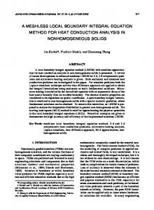
A complete report on the construction of the shape functions defining the EFGM can be found in many papers [10, 11, 12]. This paragraph gives only a brief overview of the main steps in the particular case of 2D problems. The MLSA is defined on a cloud of n nodes, which are not connected by elements as it is required for the Finite Element Method (FEM). The nodes are located at xI = (xI , yI ) inside Ω (I = 1, . . . , n). For each node I, we define a domain of influence characterised by a typical dimension size dinfl,I (for two-dimensional problems, the domain is a disc of radius dinfl,I or a square of half lengthside dinfl,I ). These domains are defined to connect the nodes: two nodes are connected if their domains of influence intersect (see Fig. 1).
dinfl,I
dinfl,J
I J connection of nodes I and J
Figure 1: Circular domains of influence and connection of nodes
We also define a weight function wI for each node, which is representative of the influence of the node xI at a given point x = (x, y). This function is equal to unity at the node, decreasing when the distance to the node increases and zero outside the domain of influence of the node. For all the computations reported in this paper, we have used an exponential weight function, that can be defined either on a square domain of influence as the product of two one-dimensional weight functions, y−yI 2 x−xI 2 −(2 −(2 d ) ) infl,I − e−4 e dinfl,I − e−4 e (x ≤ dinfl,I and y ≤ dinfl,I ) 1 − e−4 1 − e−4 wI (x, y) = 0 (x > dinfl,I or y > dinfl,I ) or on a circular domain as a function of d, the distance between point x and node x I : −(2 d d )2 inf l,I − e−4 e (d ≤ dinfl,I ) −4 1−e wI (x, y) = 0 (d > dinflI ) 5
(18)
(19)
The construction of the MLSA and the corresponding shape functions is based on the choice of a basis P (x) (dimension m) of functions which, in the case of 2D polynomials, are P t (x) = P t (x, y) = {1, x, y} (linear basis, m = 3)
(20)
P t (x) = P t (x, y) = {1, x, y, xy, x2 , y 2 } (quadratic basis, m = 6)
(21)
It is important to notice that polynomial bases are not the only choice: non-polynomial bases can also be chosen, as it will be seen in section 6. For example, the basis can contain some terms a priori satisfying the homogeneous governing equations of the problem; this procedure can be seen as a parallel to the Trefftz approach. This introduces for instance functions better suited for solving the Helmholtz equation. The unknown ph (acoustic pressure, the upper h stands for numerical solution) of the problem is built from ph (x) = P t (x) a(x)
(22)
where the a(x) coefficients are non constant and are determined by minimising a given norm (see References [10, 11]), leading to a (x) = A−1 (x) B (x) p
(23)
where p is the array of the nodal values pI . A(x) and B(x) are the matrices defined by A (x) =
n X
wI (x) P (xI ) P t (xI )
(24)
I=1
B (x) = [w1 (x) P (x1 ) ,
...,
wn (x) P (xn )]
(25)
where n is the number of nodes. Equation (22) can then be written as ph (x) = N (x) p
(26)
where N (x) contains the shape functions and is defined by: N (x) = P t (x) A−1 (x) B (x) .
(27)
Figure 2 represents a shape function as well as its first x-derivative, in the two-dimensional case, for an interior node of a regular distribution of nodes (the internodal spacing is called h and is constant). The linear basis (20) is used and the sizes of the domains of influence are chosen identical for all nodes (the value considered for Fig. 2 is dinfl = 3h). Note that for square domains and for the limit case, dinfl → h
(28)
the EFGM shape functions tend to the standard FEM bilinear shape functions defined on a regular mesh (Fig. 3).
6
Figure 2: EFGM 2D-shape function and its first x -derivative (linear basis, regular distribution of nodes, square domains of influence with dinfl = 3h)
Figure 3: With a linear basis, a regular distribution of nodes, square domains of influence with dinfl→ h, the EFGM shape function tends to the standard FEM bilinear shape function
7
4.2
Application to the acoustic problem
The application of the EFGM to the acoustic problem formulated in Sections 2 and 3 is completely detailed in Reference [12]. We choose to approximate the acoustic pressure field and its variation by, ph = N p
δph = N δp
(29)
while the Lagrange multipliers and their variation are chosen to be, λh = N λ
δph = N δλ
(30)
where N is a Lagrange interpolant. Introducing Eqs. (29)-(30) into the variational form (17), we obtain a linear system of equations similar to the system obtained for a problem of structural dynamics, K + jρckC − c2 k 2 M K pλ p −jρckf = Λ K tpλ 0 b
(31)
where the matrices and vectors are defined as follows: • the ”stiffness” matrix K,
Z t
K=
(∇N ) (∇N ) dΩ
(32)
Ω
• the ”damping” matrix C (Robin boundary conditions), Z C= N t N An dΓ
(33)
ΓR
• the ”mass” matrix M , 1 M= 2 c
Z N tN
dΩ
(34)
Ω
• the vector p of nodal pressure unknowns, • the vector Λ of nodal Lagrange multipliers unknowns, • the matrix K pλ , coupling the two types of unknowns, Z K pλ = N t N dΓ
(35)
ΓD
• the vector f , containing the prescribed normal velocities (Neumann boundary conditions), Z f= N t v¯n dΓ
(36)
ΓN
the vector b, containing the prescribed values of the pressure (Dirichlet boundary conditions), Z b= N t p¯ dΓ ΓD
8
(37)
5
Dispersion analysis for 2D Helmholtz equation
The numerical computation of waves always encounters a major problem: the dispersion effect. The numerical wave does not propagate at the same speed as the exact one, the dispersion can thus be observed as a difference of phase between both waves. For a given numerical Galerkin method, the difference can be predicted, depending on the wavenumber k. This a priori computation of the dispersion has first been developed for standard FEM and other modified finite element methods (GLS, QSFEM, RFFEM,. . .) in Reference [15]. It is also detailed in [16] for the one dimensional EFGM case, and is presented in [20] for the two dimensional EFGM computations. The dispersion is measured by the error, ε=
k − kh kh − k h h = k kh
(38)
defined as the relative phase difference between the exact (k) and numerical (k h ) wavenumbers. When computing the dispersion error, we have to consider a regular distribution of nodes of internodal spacing h. All the domains of influence have the same size dinfl (defined in Section 3). They will be rectangular domains of influence, the square domains being a particular case. This assumption is in no case a restriction: the equations are also valid for circular domains of influence when replacing by zero the contribution of points located outside the circle but inside the square.
6
Numerical results for the dispersion
We present here a set of two-dimensional results of dispersion obtained for the EFGM. For more numerical results and comparisons with other numerical methods, the reader will refer to [20]. Here, we will present in Section 6.1. a few dispersion results when a polynomial basis is used to build the EFGM shape functions. Moreover, Section 6.2. presents dispersion results for special bases, leading to frequency-dependant shape functions. As mentioned in Section 4, the shape functions are built from a basis containing terms which are solution of the governing homogeneous equations, which is similar to a Trefftz approach. They enable us to obtain an improved accuracy for the numerical solution.
6.1
Study of EFGM dispersion with a polynomial basis
Throughout this whole section, we will focus on the EFGM built with polynomial bases. Some results (linear FEM and EFGM with a linear basis (20) and an optimum value of the size of the domains of influence dinfl = 3.0h) are plotted in Fig. 4. For three different values of θ, the computed value of k h h is presented as a function of kh, and compared to kh. It can be seen, from Fig. 4, that the dispersion error increases when kh increases. But it has to be noticed that EFGM with dinfl = 3.0h has a much better behaviour than FEM. These results show the advantages of 9
4
4 kh k h , θ = 0 deg . k h h , θ = 30 deg . k hh , θ = 45 deg .
t
( b a sis P ( x ) = { 1 ,x , y } )
3.5
kh k h h , θ = 0 deg . k h h , θ = 30 deg . k h h , θ = 45 deg .
t
( b a sis P ( x ) = { 1 ,x , y } )
h
3.5
3
3
d in fl = 1 .0 h (F E M )
2.5 2
d in fl = 3 .0 h
2.5 2
1.5
1.5
1
1
0.5
0.5
kh
kh 0
0 0
0.5
1
1 .5
2
2 .5
3
0
0.5
1
(a)
1 .5
2
2 .5
3
(b)
Figure 4: Dispersion wavenumber of the EFGM wave, for θ = 0, 30 and 45 degrees (a) linear FEM (b) linear EFGM with dinfl = 1.5h
the EFGM as compared to the standard FEM when it is applied to the resolution of the Helmholtz equation. The size dinfl of the domains of influence is an important parameter of the EFGM. Dispersion computations can be performed for different values of this parameter [12, 20], and the conclusions are that there is an optimal range given by 2h < dinfl < 3h. We will now examine the evolution of the dispersion error with the angle of propagation θ of the plane wave. This is done in Fig. 5, where we compare FEM and EFGM solutions (dinfl = 2.5h, linear basis), for two values of the non-dimensional wavenumber (kh = 1.0 and kh = 2.5). We can note that for both methods, the dispersion is maximum for θ = 0, while a minimum for the dispersion is reached when the angle is equal to 45 degrees. We can also already notice the significant improvement of switching from standard FEM to EFGM in terms of dispersion: it is reduced by a factor around 50, which is even larger for some values of θ.
6.2
Further reduction of the dispersion: frequency-dependant shape functions
As it has already been mentioned in Section 4, it is possible to construct shape functions that are better suited for the wave representation, especially for high wavenumbers. These shape functions include an oscillatory behaviour and are frequency-dependent: they make use of a basis including sine and cosine terms, which are solutions of the governing homogeneous equations, as it is the case in a Trefftz approach. We remember that the 1D basis used in Reference [16] was given by, P t (x) = {1, cos (kx) , sin (kx)}
(39)
enabling us to completely eliminate the dispersion in101D: the waves of wavenumber k can be exactly represented by the basis functions, and the EFGM solution is exact everywhere. For the 2D case, it is not possible to eliminate completely the dispersion for every θ by the use of a numerical method, as it can be theoretically proved (Reference [6]). But it is possible to eliminate it for some values of θ, and minimise it for the close values. Consider for example the use of the following basis
0 .2
0 .05 E F G M , d in fl = 2.5 h F EM
d isp ersio n er ro r ( ε)
0 .04 5
E FG M , d in fl = 2.5 h F EM
d ispersio n err or ( ε)
0.04
0.15 0 .03 5 0.0 3
0 .1
0 .02 5 0 .02
kh = 1 .0
k h = 1 .0
0 .01 5
t
t
( ba sis P ( x ) = { 1 , x , y } )
( b asis P ( x ) = {1 , x , y } )
0 .05
0.0 1 0 .00 5
θ (de g.)
θ (d eg .) 0
0 0
10
20
30
40
50
60
70
80
0
90
(a)
10
20
30
40
50
60
70
80
90
(b)
Figure 5: Dispersion error as a function of θ. Comparison of standard FEM and EFGM with dinfl = 2.5h. (a) kh = 1.0 (b) kh = 2.5
Figure 6: Frequency-dependent shape function and its first x-derivative, built from basis (40), with kh = 4.0 and θ˜ = 30 degrees.
11
As expected, we can observe in Figs. 7.a and 7.b that the dispersion error is zero when θ = θ˜ and θ = θ˜ + π/2, because the EFGM shape functions are able to exactly reproduce the plane waves propagating in those directions. The error for angles close to these values is relatively low. However, the dispersion for the wave of angle θ = θ˜ + π/4 is rather high, and higher than the corresponding one obtained with a linear basis (refer to Fig. 5.b): this is obviously due to the fact that the basis and the corresponding shape functions are not well suited for this angle of propagation. The remedy to this last problem can be easily found. The frequency dependent basis can be enriched with other basis functions, corresponding to other angles of propagation. Consider for example the following basis: ³ ´ ³ ´ P t (x) = {1, cos kx cos θ˜1 + ky sin θ˜1 , sin kx cos θ˜1 + ky sin θ˜1 , ³ ´ ³ ´ cos −kx sin θ˜1 + ky cos θ˜1 , sin −kx sin θ˜1 + ky cos θ˜1 , ³ ´ ³ ´ cos kx cos θ˜2 + ky sin θ˜2 , sin kx cos θ˜2 + ky sin θ˜2 , ³ ´ ³ ´ cos −kx sin θ˜2 + ky cos θ˜2 , sin −kx sin θ˜2 + ky cos θ˜2 } (41) It leads to the exact solution for θ˜1 , θ˜2 , θ˜1 + π/2 and θ˜2 + π/2. Figure 8 shows the dispersion results obtained with kh = 2.5. The two angles chosen are θ˜1 = 0 and θ˜2 =45 degrees. The dispersion error is zero for the directions of propagation contained in the basis, and it is kept at a very low level for other directions (smaller than 0.002 for kh = 2.5, while the corresponding error for standard FEM is in the range 0.10 to 0.15, Fig. 5.b). However, we have to keep in mind that adding functions to the basis implies increasing the size of the domains of influence, and consequently the number of computations. We can conclude from this subsection that the shape functions including a priori knowledge on the solution lead to an improved accuracy. It is shown in [20] that the EFGM is better than stabilised the FEM and leads to dispersion errors comparable to the QSFEM [6], while remaining more general: the EFGM can be applied on irregular distributions of nodes.
7
Numerical tests on a model problem
We consider a real-life problem to show that the EFGM is really efficient and contributes to the reduction of the dispersion in cases where the solutions are not plane waves. The problem (see Fig. 9.a) is a 2D-section in the bodywork of a car, Reference [17]. The air inside the cabin is excited by the vibrations due to the engine through the front panel (Neumann boundary conditions). The roof is covered with an absorbant material (Robin boundary conditions). As an example, we study the acoustic response inside the car at a frequency of 500Hz. Three computations have been performed. We consider first a FEM discretization of linear elements and 12
0 .01
d isp e rsio n erro r ( ε)
0.0 7
kh = 2 .5 (fre qu en c y de p en d a n t b asis w ith ~ θ = 0)
0.0 6 0.05
d isp e rsio n er ro r ( ε)
0 .00 9
kh = 2 .5
0 .00 8
(fr eq uen c y d ep end a n t b a sis w ith ~ θ = 45 d eg .)
0 .00 7 0 .00 6
0.0 4
0 .00 5
0 .03
0 .00 4 0 .00 3
0 .02
0 .00 2
0.0 1
0 .00 1
θ (de g .) 0
θ (d eg .)
0
0
10
20
30
40
50
60
70
80
90
0
10
20
30
(a)
40
50
60
70
80
90
(b)
Figure 7: Dispersion error ε(kh = 2.5) for the frequency-dependent shape functions built from basis (40). (a) θ˜ = 0 (b) θ˜ = 45 degrees.
0 .00 2
d isp ersio n e rror ( ε)
kh = 2 .5 (fr equ en c y d ep end a n t b a sis w ith ~ θ1 = 0 an d ~ θ2 = 4 5 d eg . )
0 .001 5
0 .00 1
0 .00 05
θ (d eg .)
0 0
10
20
30
40
50
60
70
80
90
Figure 8: Dispersion error ε(kh = 2.5) for the frequency-dependent shape functions built from basis (41). θ˜1 = 0 and θ˜2 = 45 degrees.
13
Absorbant panels
fluid vibrating panel
seats vn = 1 mm/s
(a)
(b)
Figure 9: (a) Model problem (b) FEM mesh (279 nodes).
(a)
(b)
(c)
Figure 10: Distribution of the real part of the acoustic pressure at 500 Hz. (a) reference solution (FEM 17859 nodes) (b) FEM solution (279 nodes) (c) EFGM solution (279 nodes)
279 nodes (Fig. 9.b). The EFGM computation with a linear basis is performed on the same distribution of nodes as FEM. In order to compare both methods, we use as reference the FEM solution on a highly refined mesh (17859 nodes).
14
0 .005 0 .004
FE M 17 859 nod es FE M 279 no des E FG M 2 79 nod es
R ea l p a rt o f the ac o ustic p ressu re at 5 00 H z
0 .003 0 .002 0 .001 0 -0.00 1 -0.0 02 -0.0 03
(a)
(b)
Figure 11: (a) Distribution of the real part of the acoustic pressure at 500Hz along the straight line (b) definition of the straight line
Figure 10 presents the results of the three computations for the distribution of the real part of the acoustic pressure inside the car at a frequency of 500Hz. The graph in Fig. 11.a presents the same results, computed along the straight line defined in Fig. 11.b. These figures show the advantages of the EFGM as compared to the FEM, for the numerical wavenumber as well as for the amplitude of the wave. Considering the plots of Fig. 10, we can easily observe the wavefronts, especially in the region above the seat. The EFGM solution exhibits a good behaviour, while the FEM wave presents an important phase lag, when compared to the reference solution. This is confirmed in the cut view of Fig. 11a, where we can also see that the amplitude of the EFGM wave is really much than the FEM one. We can conclude from this that the EFGM is applicable to real-life acoustic problems, and in this case, when compared to the standard FEM with the same number of nodes, the EFGM is really more efficient than the FEM, leading to a lower error in terms of wavenumber and amplitude. As it has already been said in Section 7, the EFGM combines two advantages: it is very efficient in terms of reduction of the dispersion, and its formulation is general and easily applicable to real life problems, where its behaviour reveals to be very good.
8
Conclusions
The focus of the computations presented here is on the dispersion error. Because the control of this error leads to uneconomical meshes, we are looking for a method for which the dispersion error is very small and negligible as compared to the local error. We show that a meshless approach, based on the Element-Free Galerkin method, gives very accurate results. In comparison with the stabilised finite element method, it is
15
shown that the EFGM is almost as accurate as the QSFEM. However, it has to be noticed that the QSFEM is not adapted to non uniform meshes and irregular boundaries, which is not the case in the present paper. This is further illustrated by a 2D industrial computation. Moreover, we observe, just like I. Babuˇska and J. Melenk [8], that it is possible to use a basis containing the exact solution of the Helmholtz equation. This approach is similar to the Trefftz formulation, as it includes in the formulation some terms that are solutions of the governing homogeneous equations. This allows us to completely cancel the dispersion effect for some particular directions of propagation.
References [1] F. Ihlenburg, I. Babuˇska. Finite Element Solution of the Helmholtz Equation with High Wave Number. Part 1: The h-Version of the FEM. Computers Math. Applic.. 38(9):9–37, (1995). [2] Ph. Bouillard, F. Ihlenburg. Error estimation and adaptivity for the finite element solution in acoustics. In P. Ladev`eze & J. T. Oden (Eds.), Advances in Adaptive Computational Methods in Mechanics, Elsevier, (1998). [3] F. Ihlenburg, I. Babuˇska. Dispersion Analysis and Error Estimation of Galerkin Finite Element Methods for the Helmholtz Equation. Int. j. numer. methods eng. 38:3745-3774, (1995). [4] I. Babuˇska, F. Ihlenburg, T. Strouboulis, S. K. Gangaraj. A posteriori Error Estimation for Finite Element Solutions of Helmholtz’ Equation. Part I: the Quality of Local Indicators and Estimators. Int. j. numer. methods eng. 40:3443-3462, (1997). [5] I. Harari, K. Grosh, T. J. R. Hughes, M. Malhotra, P. M. Pinsky, J. R. Stewart, L. L. Thompson. Recent Developments in Finite Element Methods for Structural Acoustics. Arch. of Comp. Meth. Eng. 3:131-311, (1996). [6] I. Babuˇska, F. Ihlenburg, E. Paik and S. Sauter. A Generalized Finite Element Method for solving the Helmholtz equation in two dimensions with minimal pollution. Comput. Methods Appl. Mech. Eng. 128:325-359, (1995). [7] L. Franca, C. Farhat, A. Macedo, M. Lessoine. Residual-Free Bubbles for the Helmholtz Equation. Int. j. numer. methods eng. 40:4003-4009, (1997). [8] I. Babuˇska, J. M. Melenk. The partition of unity method. Int. j. numer. methods eng. 40:727-758, (1997). [9] P. Lancaster, K. Salkausas. Surfaces generated by moving least squares methods. Math. Comput. 37:141158, (1981).
16
[10] T. Belytschko, Y. Y. Lu, L. Gu, Element-Free Galerkin Methods. Int. j. numer. methods eng. 37:229256, (1994). [11] T. Belytschko, Y. Krongauz, D. Organ, M. Fleming, P. Krysl. Meshless methods: An overview and recent developments. Comput. Methods Appl. Mech. Eng. 139:3-47, (1996). [12] Ph. Bouillard, S. Suleau. Element-free Galerkin solutions for Helmholtz problems: formulation and numerical assessment of the pollution effect. Comput. Methods Appl. Mech. Eng. 162:317-335, (1998). [13] I. Kaljevic, S. Saigal. An Improved Element Free Galerkin Formulation, Int. j. numer. methods eng., 40:2953-2974, (1997). [14] Y. Krongauz, T. Belytschko. Enforcement of essential boundary conditions in meshless approximations using finite elements. Comput. Methods Appl. Mech. Eng. 131:133-145, (1996). [15] A. Deraemaeker, I. Babuˇska, Ph. Bouillard. Dispersion and pollution of the FEM solution for the Helmholtz equation in one, two and three dimensions. Int. j. numer. methods eng. 46:471-500, (1999). [16] S. Suleau, Ph. Bouillard. 1D Dispersion analysis for the element-free Galerkin method for the Helmholtz equation. Int. j. numer. methods eng., 47(6):1169-1188, (1999). [17] D. J. Nefske. Sound in small enclosures. In L. Beranek and I. V´er (Editors), Noise and Vibration Control Engineering. Principles and Applications, 1st edition, J. Wiley & Sons, ISBN 0-471-61751-2, London, (1992). [18] I. Herrera. Trefftz method. Topics in Boundary Element Research, Vol. 1: Basic Principles and Applications, Brebbia (Ed.), 225-253, Springer-Verlag, (1985). [19] W. Desmet. A wave based prediction technique for coupled vibro-acoustic analysis, PhD dissertation, KU Leuven, Belgium, (1998). [20] S. Suleau, Ph. Bouillard. Dispersion and pollution of meshless solutions for the Helmholtz equation. Comput. Methods Appl. Mech. Eng., in print, (2000).
17