set of visual landmarks from a panoramic sensor that allows for accurate local ... tion about visual landmarks provides accurate local position- ing within .... Ð EQS RU T¦ Y ahpУÐq8 EQr g EQ§ Re TТVbQX Ð ht У$qX EQX 9 Rv ЧS QÐ Re T©.
Proceedings of the 2002 IEEE International Conference on Robotics & Automation Washington, DC • May 2002
Accurate Local Positioning using Visual Landmarks from a Panoramic Sensor Simon Thompson and Alexander Zelinsky Research School of Information Sciences and Engineering The Australian National University, Canberra, Australia. Email: simon � alex� @syseng.anu.edu.au visual field can capture almost all of the robots environment, making such representations rotation invariant and resistant to occlusion. Their low resolution and absence of depth information, however, mean that accurate local positioning is difficult. Insects with near monocular vision and large fields of view, such as wasps, are capable of performing accurate navigation tasks. They have been observed to perform “flights of learning” when leaving their hives [4]. Turn Back and Look (TBL) flights are used to form reliable representations of the hive, allowing for accurate navigation upon the insects return. [5] report a robotic system which uses a TBL move to select landmarks from a monocular camera.
Abstract This paper presents a method for representing places using a set of visual landmarks from a panoramic sensor that allows for accurate local positioning while still providing efficient global localisation. For each place landmarks are selected for their local uniqueness in the panoramic visual field and their dynamic reliability over a Turn Back and Look movement. During this movement, the depth of landmarks is also estimated using a bearing only SLAM approach. Accurate local position tracking within places equal to that of laser range finder systems is obtained by the application of the Condensation algorithm over individual places. A topological map of such places is built and both global localisation and position tracking experiments are carried out.
It has been suggested that these flights are also used to extract depth information from the environment [4]. This paper proposes a place representation for use in topological maps that uses TBL movements to extract unique visual landmarks and their depth from a panoramic sensor. The depth information about visual landmarks provides accurate local positioning within places while maintaining efficient global localisation. The goal is to achieve local positioning accuracy equivalent to that of systems using metric maps and laser sensors.
1 Introduction There are traditionally two opposing approaches towards mapping: topological vs metric. Topological maps are typically coarse, graph like representations of the environment [1]. Metric maps on the other hand are usually fine grained metric models of the environment generated from sensor scans from different robot poses [2]. While the coarse representation of topological maps limits the accuracy of position tracking, it conversely simplifies the global localisation task, that is, localising the robot from an unknown start position. Metric maps have a fine level of representation of the environment and can therefore be used to track the position of the robot very accurately. The amount of information they contain however can limit the scale of the maps, and increases the difficulty of the global localisation task.
1.1 System Overview Individual places are defined by a unique set of automatically selected visual landmarks and their associated depth. Section 2 describes the process of learning such a place and estimating landmark depth from the panoramic sensor. Within each place the set of landmarks can be used for accurate local positioning. Two types of local positioning are implemented, heuristic and probabilistic, the details and performance of which are reported in Section 3. A series of these learnt places form a simple topological map as shown in Section 4. Here a place discrimination experiment is presented as well as an initial attempt to accurately localise within a learnt map. Section 5 discusses these results and suggests some areas for future work.
Localisation systems using vision sensors typically use the rich sensor data to define unique topological places while systems using poorer sensors such as laser range finders typically use entire sensor readings or the extraction of non-unique features to form metric maps. [3] describe a topological map represented by entire panoramic images, which define unique places 50cm apart, but do not allow for accurate local positioning within a place.[2] use a laser sensor and occupancy grids to accurately localise to within 10cm but can not perform global localisation efficiently. Panoramic vision sensors are good for extracting unique representations of places as their
0-7803-7272-7/02/$17.00 © 2002 IEEE
2 Learning a Place Learning a particular place in the environment involves extracting a suitable representation which uniquely defines that place. The process of automatic landmark selection is aimed at producing a set of landmarks which are unique, maximise the area of the environment the place represents, and allow for
2656
p. 1
which the static landmarks were selected while observing the potential landmarks. By tracking the landmarks throughout this movement, the landmark’s resistance to changes in lighting and perspective can be measured. By selecting landmarks which track reliably throughout the TBL move, a landmark set with greater reliability and coverage can be obtained. Tracking is achieved by performing a normalised cross-correlation match in a ������� � search window which expands when tracking is lost. This system selects 32 static landmarks, choosing 16 from the dynamic selection phase, with 4 from each sector of the panoramic image.
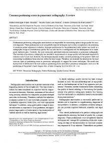
Figure 1: An example of unique visual landmarks selected from a panoramic image lm(i)
Knowledge of depth of landmarks in the environment is valuable for robot localisation as is shown in the later experiments. While performing the TBL move and tracking landmarks, a form of bearing only SLAM can be used to estimate the depths of potential landmarks. [8] describes a panoramic bearing only SLAM system which uses the structure from motion technique of bundle adjustment to initialise a Kalman filter before the iterative estimation process can be performed. The problem can be reformulated into estimating the depth and angle of each landmark (as opposed to �� ���� landmark position), with the resulting estimates more directly reflecting the uncertainty in the observations. The current system uses a Kalman filter to estimate the state of the system in relation to reference point of the place to be learnt, with the state � defined as:
d(i)
O(i,0)
O(i,j)
Figure 2: Modified TBL move
accurate local positioning. This means that landmarks must be reliable, strongly identifiable, and they must be distributed throughout the image. They also must be able to withstand distortions due to temporal and translational distortions. To this end [5] proposed a method which selects landmarks based on their static uniqueness and their dynamic reliability. This approach has been extended to incorporate the advantages of the panoramic sensor [6], and to include an estimate of landmark depth. In this system visual landmarks are 16 � 16 pixel regions in the panoramic image, their observed angles and a depth estimate from the reference position (ie the location of the place being learnt). The two phases of landmark selection, static and dynamic, are described below.
���
���
���
���
�������!�"��$#%�&# '
where, (���) ����* "�+�,� describe the robot pose, while -�$.� ��/.0� describe the depth and observed angle of landmark 1 . The filter has the traditional prediction phase:
�2 �35476 893:�;�=3:�- �?@ -354A6 �B� C
C
�3�476 893:�;�EDF3:�UDJ]�G: -3:� '
�3Y4A6 � Z
-35476��;�=DF]SG& -3H�
C
-3�4A6\8>3:�UDJ]�G: -3:� ' 4La5 �3Y4A6 �
where DF]SG is the observation Jacobian and a5 -3b4F6 � the noise in the observation. In the current formulation the observation Jacobian DF]SG becomes:
2.2 Dynamic Landmark Selection Landmarks selected for their static uniqueness are then evaluated for their dynamic reliability. In this phase the robot performs a TBL move (see Figure 2) about the position from
DF] G �
2657
c
ceGgd f
cBd f cBh
cBd f cBi
""
ced cejlk
cBd cBmlk
"� p. 2
Actual robot and landmark positions 400
300 lm7
200
lm1
lm4 Y position
100 lm5 0
−100
−200
lm8
lm2
lm6
lm3 −300
−400 −400
−300
−200
−100
0 100 X position
200
300
400
a) Estimated landmark and robot positions after move 400 400
300
Figure 4: Estimated landmark depth and variance from real data
lm7
200
lm1
lm4 Y position
100 lm5
1000mm. With the nature of visual landmarks being such that they can contain objects from different depths, the estimation process is much noisier than with a simulated system, and a measurement of ground truth can be equally hard to obtain. The results here provide a good estimate of landmark depth as well as a variance measurement in accordance to the noisy nature of the landmarks used.
0
−100
−200
lm2
−400 −400
lm8
lm6
lm3
−300
−300
−200
−100
0 100 X position
200
300
400
b)
The cycle of capturing the panoramic image, tracking the 32 landmarks and estimating the depth takes on average 135ms (Pentium II 750 - image capture and unwarping: 6.5ms, landmark tracking: 25-75ms, depth estimate 7ms).
Figure 3: Simulation results of landmark estimation over the TBL movement: a) actual and b) estimated positions and variance
The filter can be initialised using the knowledge of the exact reference location, initial observations of the landmarks and associated noise (resolution of panoramic sensor), and an initial estimate of landmark depth and variance:
���
n!n%n!n
"��� �.
� .�
"�
3 Local Positioning within Places As stated above, local positioning within topological places is desirable for navigation tasks. This section reports two methods of position estimation within a learnt place: heuristic and probabilistic. Both experiments involve the robot learning a place in the center of a large room (7x10m) and then estimating position along a path originating at the learnt place and following the crossed shaped TBL path described above. The use of the TBL move here is only for convenience, the local position estimation does not require any specific movements to work. Note that in this experiment the initial position of the robot is unknown.
n '
The iterative estimation of the system state can then proceed and continue throughout the TBL movement. Simulation results from the system show the filters ability to converge to the correct result, although for landmarks at greater depths this process can be slow. The accuracy of the estimate depends on both the depth of the landmark and the resolution of the vision sensor. Figure 3 shows an example of the simulated system: part a) shows the actual state of the system while part b) shows the estimated landmark positions after the TBL move has been performed.
3.1 Heuristic Local Positioning Figure 5 a) shows the results of using a heuristic algorithm to locally position the robot along the path. This particular method grew out of a low level homing behaviour inspired by bee navigation [9] and adapted for robot navigation by [5]. It is an instance of a reactive behaviour as the sensor information drives the robot to home to an attractive state. The algorithm uses the contraction/expansion of the observed radial distance between pairs of landmarks to estimate the position of the current robot state relative to a reference state. As you would expect, this approach allows a general estimate of position but is not suitable for navigation tasks which require accurate positioning. The direction is slightly skewed, and the scale of results is unknown. The main problem is the sensitivity to noise as shown by the zig-zag nature of the estimated path. These
Figure 4 shows the results of applying the filter in the real world using the landmarks shown in Figure 1. The resolution of the panoramic sensor is 1 pixel per degree. The noise in observations is this resolution plus an amount which grows as the correlation matching declines. The robot position is shown by the square in the center of the room and the landmarks positions and variance by the surrounding squares and ellipses. Throughout the TBL move the robot moves at 20cm/s. The room is approximately oF�P6 n meters in area and the landmarks were estimated to within roughly p 500mm, with the exception of those landmarks in the doorway which were within
2658
p. 3
Local Positioning using Contraction Algorithm (Unscaled)
Sensor Model Evaulated Over (−1000,+1000) for Observation at (495,0): 1 Landmark
5
1 Probability
4
3
2
0.5
0
1000
1
500 Y
0
−1
0
−2
−500 −3
Y position (mm) −1000
−4
−5 −5
−4
−3
−2
−1
0 X
1
2
3
4
1000
500
0
−500
−1000
X position (mm)
a)
5
a)
Sensor Model Evaulated Over (−1000,+1000) for Observation at (495,0)
Probabilistic Local Position Estimation 600
−3
x 10
Observation Probability
2
400
Y position
200
1.5
1
0.5
0 1000
0
1000 500
500 0
0 −500
−200
Y position (mm)
−1000
X position (mm)
b)
−400
−600 −600
−500 −1000
−400
−200
0 X position
200
400
Figure 6: Probability distribution of sensor model over the possible
600
X,Y state space given an observation made at (495,0) for a) 1 landmark and b) all 16 landmarks
b) Figure 5: Local positioning along TBL path using a) heuristic and
A standard holonomic motion model is used in the prediction phase. A sensor model has been derived to suit the landmark based place representation. Below, the sensor model is described and experiments in local positioning are reported.
b) probabilistic algorithm
characteristics are typical of attractor-based methods typical of topological representations and do not allow for accurate local positioning.
3.3 Sensor Model The sensor model is derived to suit the landmark based place representation, with the observation input being the observed radial angles of landmarks in panoramic images. The radial angles are taken relative to the current rotation of the robot. By comparing them with the observation angles from the reference position where the place was learnt, an estimate of the probability of a particular pose relative to the reference position can be calculated. Note, this does not require knowledge of the absolute angles of landmarks, only those relative to the reference position. Z The sensor model’s input consists of a state sample . , the radial angles of landmarks from the learnt place, } � , and the radial angles of the observed landmarks from the current image },~ . For a particular observation }~ , there are ���>("# angles, where u is the number of landmarks in a landmark set. Z C The probability �"/� , given state . of observing angle " , "L}~ n
3 u , is a mixed distribution composed from CU0 # , the probability of the the two following distributions: j sensor returning a noisy random result: C 0 # �E6\"�$v j Z C� s and . , the probability that at state . , the sensor correctly C� s observed landmark 9 . . is defined as ^I `|Be � C s 6 . �O/t - � �$vS
3.2 Probabilistic Local Position Estimator The benefits of probabilistic reasoning in mobile robot localisation has been widely reported [10]. By using knowledge of past observations and ego-motion, the position of the robot can be represented as a probability distribution throughout the state space of possible robot poses in the environment, allowing for multi-modal hypotheses. Particle filters have been used successfully to reduce the computational requirements of generating the distribution, by random sampling of the state space. The Condensation algorithm [11] [2] is one such method, and Z*q �0r Z*q #tr is summarised below . A set of sampled states s >( s (where uX� the number of particles or samples used), and their q �0r q #tr associated probabilities (v s (> v s ), are used to approximate the probability distribution at time w . At each iteration of the algorithm, the following steps are applied:
Z�xyq .9r Z�z 1. Resample: For each particle s in s , select a random Z q|{ r Z s particle s ^�_ from ^�_ . This resampling is done with Z*q|{ r replacement and probability of selecting s ^`_ is given q|{ r by v s ^`_ . Z xyq .9r Z z 2. Predict: For each particle s in s predict a new state Z q .9r Z s s in by applying the motion model. Z)q .|r Z 3. Measure: For each particle s in s , evaluate the probqs .|r ability v using the sensor model.
where /t - � is the matching correlation between the reference and current images for landmark , � the intersection
2659
p. 4
depth of with the reference observation, � and the estimated depth and variance of the landmark. These distributions are combined by a weighted sum based on their relative importance:
C
C�0
-":�;�
#
j�¡
0 #
j
4
C� s . ¡
s .
and then the product of the independent observations gives the final probability:
C
#
-}��b�
£¢I�
C
-"/�
Figure 7: Estimated robot position along path using probabilistic estimation of local positioning.
The correspondence problem of mis-matching landmarks is addressed by using the /t � � to weight the probability of correct observation. Landmarks which do not correlate highly will relieve little support. In addition, probabilistic reasoning over time will eliminate highly correlated false positives while maintaining multiple hypotheses proposed by other landmarks. This characteristic, in conjunction with the field of view of the panoramic sensor, allows occlusion of landmarks to be overcome, depending on the degree of occlusion on the visual field.
Place Discrimination with Enhanced Correlation Averages
Average Correlation %
1
0.9
0.8
0.7
0.6
0
100
200
300 400 Image Number
500
600
700
Figure 8: Enhanced place discrimination between sets of visual landmarks in a corridor environment.
Figure 6 shows the output of the sensor model given an observation made at the position (495,0) for a) 1 landmark and b) for all 16 landmarks. The surface of the graphs show the probability of making that particular observation over the state space.
shows a map constructed in the corridors of the Robotic Systems Lab at the Australian National University. It contains 15 learnt places over a 25 meter long path. Global localisation is simply a matter of matching sets of landmarks, to the current visual scene. Currently a brute force offline search of landmarks throughout the entire image is undertaken for each set of landmarks at each image. The robot is assumed to be in the place associated with the set of landmarks which have the highest average correlation in the current scene.
3.4 Particle Filter Results Figure 5 b) shows the results of using the particle filter to localise the robot along the TBL path. Particles were initially randomly spread throughout a BT56 n�n n¥¤ 6 n�n n )mm square about the reference position. In this experiment 1000 particles were used, and the estimated position was said to be the weighted average of all the particles. The estimated path does not suffer from the axis skew and loss of scale seen in the heuristic estimator, due to the introduction of odometric information and the probabilistic reasoning, and a much more accurate estimate of local position can be achieved. The estimated position in this experiment are within p,¦ n$§F§ of the odometric data. This result is comparable to metric map based approaches. Again the robot moved at 20m/s. Each capture image, track landmark, and estimate local position took approximately 300ms for 1000 samples.
4.1 Place Discrimination This experiment seeks to validate the chosen place representation by evaluating the place discrimination ability of the system over a map with a dynamic, highly structured and visually sparse environment. Figure 8 displays the place discrimination performance over a 25 meter corridor path containing 15 places, plotting each landmark sets average correlation for each image along the path. The robot path was captured which passed over all 15 places in the map. The path was captured on a separate day and at a different time from when the map was learnt. Doors were opened/shut and people were walking the corridor. Each line in Figure 8 is the average correlation of a landmark set associated with a particular place. The plots are enhanced by decaying the correlation of those sets which are further away from the current best correlated place. Examples of the natural place recognition (solid line) and the enhancements (dotted line) are shown in Figure 9. The peaks show when the landmark set is correlated with images closest to the learnt place.
4 Global Localisation A topological map of the robot environment can be constructed by learning a series of places along a path and associating them with information which describes the transitions between places. The map is built by moving the robot around the environment and manually telling the robot when to learn a place. Places were learnt by the method described above and transitions between places were represented by a heading and distance measure defined relative to the learnt place. Figure 7
2660
p. 5
Enhanced vs Normal Place Recogintion for 4 Places Over Path
Estimating position over longer paths between places was not clearly demonstrated but future experiments should confirm the current systems applicability. Future work includes extending the system to automatically decide when to learn new places and investigating the recovery of position tracking after loss. A probabilistic approach to global localisation is needed which provides a quick way of searching through landmark sets is necessary to increase the systems scalability.
1
0.8
Average Correlation %
0.6
0
100
200
300
400
500
600
700
0
100
200
300
400
500
600
700
0
100
200
300
400
500
600
700
0
100
200
300 400 Image Number
500
600
700
1 0.9 0.8 0.7 1 0.9 0.8 0.7 1
0.8
0.6
Figure 9: Place recognition for 4 places along route: natural (solid line) and enhanced (dotted line).
Throughout the path the system correctly identifies the nearest place thus demonstrating the system maintains the unique place representation desirable in topological maps. 4.2 Local Positioning and the Topological Map Local Positioning can be used in conjunction with the topological map to estimate the robot’s position along a route through the map. Figure 7 shows the results of a first try at such an experiment, using 2,000 samples in the particle filter. The results of the place discrimination experiment were used to determine where to perform local position estimation. Upon a place transition detection, the local estimate is transferred to the next place by using the associated transition data. This way the local estimate is maintained between places and repositioning does not have to be performed when entering a new place. The estimated path drifted of the actual path. Along the longer path segment, this drift was bounded and ceased to grow at about 15cm off center. This bound is determined by the resolution in the sensor for detecting displacements in landmark angles when the landmarks are far away (such as at the ends of the corridors). After the 90 degree turn, however, the drift appeared to grow without a bound. This was due to the local position probability distribution losing samples around the correct position because of sensor and odometric noise, and an inability to recover due to the nature of the Condensation algorithm. Although position tracking was lost, the results show the potential of the current approach in obtaining an estimate of local position from images captured from a panoramic sensor. Experiments are underway to validate this approach further. 5 Conclusions and Further Work This paper has presented a new method for accurate local positioning within places represented by landmarks extracted from panoramic images. The place representation is unique and uses estimates of the depth of visual landmarks to aid local positioning. Experimental results validate the depth estimation process and local positioning accuracy in individual places.
References [1] B. Kuipers and Y. Byun, “A robot exploration and mapping strategy based on a semantic hierarchy of spatial representations,” Journal of Robotics and Autonomous Systems, vol. 8, pp. 47–63, 1993. [2] F. Dellaert, D. Fox, W. Burgard, and S. Thrun, “Monte carlo localization for mobile robots,” in Proceedings of 1999 International Conference on Robotics and Automation, 1999. [3] Y. Matsumoto, M. Inaba, and H. Inoue, “Memory-based navigation using omni-view sequence,” in Int. Conf. of Field and Service Robotics, 1997, pp. 184–191. [4] T.S. Collet and J. Zeil, “Flights of learning,” Journal of the American Psychological Society, pp. 149–155, 1996. [5] G. Bianco and A. Zelinsky, “Biologically inspired visual landmark learning and navigation for mobile robots,” in Proceedings of the 1999 IEEE/RSJ International Conference on Intelligent Robotic Systems (IROS ’99), 1999, vol. 2, pp. 671– 676. [6] S. Thompson, T. Matsui, and A. Zelinsky, “Localisation using automatically selected landmarks from panoramic images,” in Proceedings of Australian Conference on Robotics and Automation, 2000. [7] T. Mori, Y.Matsumoto, T. Shibata, M. Inaba, and H. Inoue, “Trackable attention point generate based on classification of correlation value distribution.,” in JSME Annual Conf. on Robotics and Mechatronics (ROBOMEC 95)., 1995, pp. 1076–1079. [8] M. Deans and M. Hebert, “Experimental comparison of techniques for localization and mapping using a bearingonly sensor,” in In International Conference on Experimental Robotics, Honolulu, Hawaii, December 2000, 2000. [9] B. Cartwright and T. Collet, “Landmark learning in bees,” Journal of Comparative Physiology, vol. A, no. 151, pp. 521– 543, 1983. [10] S. Thrun, “A bayesian approach to landmark discovery and active perception in mobile robot navigation.,” Tech. Rep., School of Computer Science Carnegie Mellon University, 1996. [11] M. Isard and A. Blake, “Condensation – conditional density propagation for visual tracking,” International Journal of Computer Vision, vol. 29, no. 1, pp. 5–28, 1998.
2661
p. 6