Loop-free routes are maintained by using ... TORA uses link-reversal [2] to recover from link ... during the local recovery phase and all updates need to be.
Achieving Loop-Free Incremental Routing in Ad Hoc Networks∗ Hari Rangarajan J. J. Garcia-Luna-Aceves Department of Computer Engineering University of California Santa Cruz, CA 95064, U.S.A. Email: {hari, jj}@cse.ucsc.edu
Abstract We present the Dynamic Incremental Routing (DIR) protocol, which features instantaneous loop-free routing of data packets based on their destination addresses (hop-byhop routing). Loop-free routes are maintained by using “feasible distances” to order the nodes with respect to a destination. Simulation results show that the performance of DIR is much better than the performance of AODV, DSR and OLSR, which are indicative of the state of the art in routing protocols.
1 Introduction Several routing protocols have been proposed to date for ad hoc networks. These protocols are either proactive (routes are maintained to every possible destination in the network) or on-demand (routes are established upon request). Pro-active protocols like the Optimized Link State Routing (OLSR) [1], Source Tree Adaptive Routing (STAR) [5], and Topology Broadcast Reverse Path Forwarding (TBRPF) [7] incur temporary loops, whereas such on-demand routing protocols like the Ad hoc On-demand Distance Vector (AODV) [9] protocol, the Dynamic Source Routing (DSR) [6] protocol, and the Temporally Ordered Routing Algorithm (TORA) [8], ensure loop freedom at every instant. DSR establishes a loop-free route to a destination by carrying the path traversed in the route request and the reverse path is then used to source route data packets. Although this approach ensures that data packets do not traverse loops, it incurs additional overhead in packet headers. On a link failure, reliable error notifications have to be sent to the source, so that a new route can be searched. The DSR draft [6] defines an operation to recover from link failures locally, ∗ This work was supported in part by the US Air Force/OSR under Grant No. F49620-00-1-0330, and by the Baskin Chair of Computer Engineering at UCSC.
by re-routing data packets along an alternative source route called packet salvaging. However, this approach results in the formation of loops and requires a mechanism to detect packets flowing in loops. TORA establishes multiple routes to a destination ondemand. TORA uses link-reversal [2] to recover from link failures by ordering nodes with a combination of route establishment timestamps and a height associated at each node per destination. A route is clamped down at a node during the local recovery phase and all updates need to be reliable for the algorithm to work. The recovery will reroute along a alternative path which was discovered during the initial route equest and it does not take into account availability of better routes due to mobility. TORA’s route setup incurs more control overhead than other on-demand routing protocols because of their need for reliable communication updates during route setup. AODV maintains loop freedom using destination sequence numbers as a routing invariant. Route requests carry the last-known sequence number, which elicits route replies with a equal or higher sequence number. Error updates can be sent unreliably, because a node increases its sequence number for a destination upon the occurrence of a link failure, and invalidates the route. This prevents upstream nodes from replying to any route requests. The Labeled Distance Routing (LDR) [4] protocol improves on the way in which AODV uses sequence numbers by using an additional invariant based on distance. LDR orders nodes by using the last known shortest distance (feasible distance) with respect to a destination, and the destination sequence number is used as a ”reset” when no path which satisfies the distance ordering can be obtained. Loop freedom can be achieved in a routing protocol if stale updates can be sorted out from fresh ones or establishing an ordering along nodes on the path to the destination, and this is usually achieved by using a combination of timestamps or sequence numbers. The problem with using timestamps is the need for a globally synchronized clock at all nodes, whereas sequence numbers would need to be
Form Approved OMB No. 0704-0188
Report Documentation Page
Public reporting burden for the collection of information is estimated to average 1 hour per response, including the time for reviewing instructions, searching existing data sources, gathering and maintaining the data needed, and completing and reviewing the collection of information. Send comments regarding this burden estimate or any other aspect of this collection of information, including suggestions for reducing this burden, to Washington Headquarters Services, Directorate for Information Operations and Reports, 1215 Jefferson Davis Highway, Suite 1204, Arlington VA 22202-4302. Respondents should be aware that notwithstanding any other provision of law, no person shall be subject to a penalty for failing to comply with a collection of information if it does not display a currently valid OMB control number.
1. REPORT DATE
3. DATES COVERED 2. REPORT TYPE
2004
00-00-2004 to 00-00-2004
4. TITLE AND SUBTITLE
5a. CONTRACT NUMBER
Achieving Loop-Free Incremental Routing in Ad Hoc Networks
5b. GRANT NUMBER 5c. PROGRAM ELEMENT NUMBER
6. AUTHOR(S)
5d. PROJECT NUMBER 5e. TASK NUMBER 5f. WORK UNIT NUMBER
7. PERFORMING ORGANIZATION NAME(S) AND ADDRESS(ES)
University of California at Santa Cruz,Department of Computer Engineering,Santa Cruz,CA,95064 9. SPONSORING/MONITORING AGENCY NAME(S) AND ADDRESS(ES)
8. PERFORMING ORGANIZATION REPORT NUMBER
10. SPONSOR/MONITOR’S ACRONYM(S) 11. SPONSOR/MONITOR’S REPORT NUMBER(S)
12. DISTRIBUTION/AVAILABILITY STATEMENT
Approved for public release; distribution unlimited 13. SUPPLEMENTARY NOTES 14. ABSTRACT 15. SUBJECT TERMS 16. SECURITY CLASSIFICATION OF:
17. LIMITATION OF ABSTRACT
a. REPORT
b. ABSTRACT
c. THIS PAGE
unclassified
unclassified
unclassified
18. NUMBER OF PAGES
19a. NAME OF RESPONSIBLE PERSON
6
Standard Form 298 (Rev. 8-98) Prescribed by ANSI Std Z39-18
Table 1. Terminology Notation dA D sA D A P SD
f dA D cA B req,rep
Description The stored distance for destination D at node A. The successor for destination D at node A. The set of neighbors of node A to whom node A has sent RREPs for D. The least distance assigned by node A A for D since P SD = φ. The cost of the link from node A to neighbor B. Superscript used for variables in a route request and a route reply.
reset eventually, which requires reliable broadcasts. This motivates the design for a new routing protocol that performs incremental (i.e, hop-by-hop) routing, uses unreliable error updates, requires no sequence number or timestamps, and no synchronization with neighbor nodes. We present the Dynamic Incremental Routing (DIR) protocol, an on-demand routing protocol for mobile wireless ad hoc networks (MANET). A strict ordering is established using distances to destinations instead of sequence numbers or timestamps, allowing DIR to avoid synchronization with any neighbor. Instantaneous loop freedom is achieved by nodes maintaining their feasible distances (i.e., the smallest distances attained to a given destination), until they can be safely reset (increased) and establishing paths that maintain the feasible distance ordering during route maintenance operations. Section 2 provides a detailed description of DIR. Section 3 provides an example of DIR’s operation. Performance of DIR against two on-demand routing protocols (AODV, DSR) and a pro-active link state protocol (OLSR) is presented in Section 4. Section 5 provides our concluding remarks.
2 Dynamic Incremental Routing Protocol (DIR)
a RREP for D (denoted by f drep D ). ADC: (Accept Distance Condition). When node A receives a RREP from node B for destination D, then Node A sets rep rep A A A sA D ←B if (dD +lcB
f dD . SDC: (Start Distance Condition). Node I can issue a RREP in response to a RREQ for destination D if I has an active route to D and dID < mf dreq D . MDC: (Minimum Distance Condition). If node A relays a rep A RREP for destination D, it sets f drep D =f dD and dD = dA . Node A relays a RREQ for destination D only if D req req A A 6∈pathreq and sets mf d =min(mf d , f d ). D D D D RDC: (Reset Distance Condition). If node A must change sdA D, A A then it sets dA D ←∞. Node A can set f dD ←∞ if dD = A ∞ and P SD = φ.
The key to loop-freedom in DIR is the dissemination of route requests (RREQ) that form a directed acyclic graph (DAG) rooted at the source, and having the route replies (RREP) traverse the reverse paths along such a DAG. RREPs establish a strict ordering of feasible distances when setting up the successor path to the destination. A RREQ traverses a loop-free path and carries the minimum feasible distance of any of its relays (MDC), and only a node with a distance strictly smaller than the minimum feasible distance can generate a RREP (SDC). Together, MDC and SDC ensure that a intermediate node replying has a loop-free path to the destination which does not contain any of the nodes in the traversed path. Because the RREP travels a loopfree path, route establishment does not create loops. However, it is essential that a strict ordering of feasible distances be established along the route traversed by the RREP. Reseting feasible distances without synchronization with upstream neighbors can create loops. A technique for reseting feasible distances is to use diffusing computations [3] which requires nodal synchronization across multiple hops. DIR uses RDC, which defines a safe condition by which nodes can determine when their feasible distance can be reset. When the predecessor set of a node is empty, the node has no upstream nodes with whom it needs to synchronize and can reset its feasible distance.
2.1 Achieving Loop freedom 2.2 Information Stored and exchanged DIR uses route request (RREQ), route reply (RREP) and route error (RERR) messages similar to other on-demand routing protocols. We use the terminology in Table. 1 to describe DIR. DIR relies on the following four rules (called conditions), which apply for a given destination D independently of other destinations. The rules make use of the minimum feasible distance of any of the nodes that relayed or originated a RREQ for destination D (denoted by mf dreq D ), and the current feasible distance of the node that transmits
Node A running DIR maintains the following entries in the routing able: (a) the successor to D (sA D ), (b) the preA ) (c) Maximum lifetime of predecessor set for D (P SD A A ) (d) the current distance decessors P SD (maxlif eP SD A The entry (dD ), and (e) the feasible distance (f dA D ). A A is the time after which nodes in P SD havmaxlif eP SD ing A as the next hop towards destination D will invalidate their routes.
A RREQ consists of the tuple {dst, src, rreqid, req mf dreq dst , pathdst }, where src represents the source seeking a route to destination dst. The rreqid is an identifier assigned to a RREQ at the source such that each (src, rreqid) pair is unique. The pathreq dst consists of a set of tuples specifying the path traversed by the RREQ. The tuple for the ith node in the path traversed is of the form {nodei , maxf di , lci }, where nodei is the node identifier for the ith path entry, maxf di is the maximum feasible distance that can be set at nodei on receiving a reply. The field lci represents the associated link cost. The RREP consists of the tuple {dst, src, ttl, drep dst , path}. The field src specifies the origin of the RREQ for which a RREP was initiated. The field ttl is the lifetime of the route at the node transmitting the RREP. The current distance towards the destination at the node relaying rep the route reply is represented by drep dst , and f ddst represents the feasible distance. f drep dst ,
A RERR message consists of the tuple {orig, dests}, where orig is the originator of the route error message and dests is the list of destinations which are no longer reachable through orig.
2.3 Route Maintenance
2.3.1 Initiating a RREQ Node A is said to be active for the route computation for the destination D when it issues a RREQ that is uniquely identified by the pair (A, IDA ). A node can be active for only a single computation for a destination at any instant of time. The route computation (A, IDA ) terminates when node A receives a RREP that is feasible at node A or the timer for the RREQ expires. The route computation terminates as success and a failure in the two cases respectively. A node A that requires a route for destination D buffers packets if it is active for destination D. Otherwise, it isreq sues a RREQ {D, A, rreqid = IDA , mf dreq dst , pathD } by setting IDA ← RequestCounter + 1; rreqid ← A IDA ; mf dreq D ←f dD ; path ← (nodeId = A, maxf d = A f dD , 0) and RREQtimer ←(2.ttl.latency), where ttl is the time-to-live of the broadcast flood and latency is the estimated per-hop latency of the network. If node A receives no RREP for destination D after its timer for (A, IDA ) RREQ expires, itsends a new RREQ with an increased ttl. If after a number of attempts node A does not receive a RREP, a failure is reported to the upper layer. The number of hops that a RREQ can traverse is controlled externally from the RREQ by means of the TTL field of the IP packet in which the RREQ is encapsulated.
2.3.2 Relaying RREQs A node relaying a RREQ originated by another node is said to be engaged in the RREQ. A node maybe engaged in multiple RREQs for the same destination, and a node that is engaged in a route computation maintains no explicit state. When node B receives RREQ {D, A, reqid = IDA , req mf dreq dst , pathD }, it first determines its own status for (A, IDA ). If B is active (i.e., B = A) or engaged (i.e., B is listed in pathreq D ) in the computation (A, IDA ), it silently drops the RREQ. Otherwise, node B is said to be passive. If this is the case and SDC is satisfied (i.e., req dB D < mf dD ), then node B issues a RREP (Section 2.3.3). Else, if SDC is not satisfied, node B relays the RREQ with req req req B mf dreq D ← min{f dD , mf dD } and pathD ← pathD ⊕ req B (nodeId = B, maxf d = mf dD , lcA ). 2.3.3 Initiating and Processing RREPs When node I processes RREQ {D, A, reqid = IDA , req I mf dreq D , pathD } and SDC is satisfied (i.e., dD < req rep mf dD ), it issues a RREP {D, src, drep ,f d D D , ttl, rep rep A I . The desand d ← d pathrep } where f d ← f d D D D D D tination or the intermediate node initiating the RREP sets req pathrep D to the reverse path pathD traversed by the RREQ. If node A receives RREP {D, src = S, f drep D , ttl, pathrep }, it determines if it is the source S of the RREQ D that caused the RREP. If so, it proceeds as Section 2.3.4 describes. If A 6= S, then it updates its routing table as Section 2.3.4 states, and forwards the RREP along pathrep D rep A A setting f drep D ← f dD and dD ← dD if node A updated its routing table after processing the RREP and f dA D ≤ rep maxf dD path.A . Otherwise, the RREP is silently dropped. A . Node A also adds the next hop of the RREP, B, to P SD 2.3.4 Adding and Updating Routes By definition, if node A has no routing-table entry for destination D, its distance and feasible distance for D are asrep sumed to have bash: a: command not found drep D ,f dD ,ttl, rep pathD } from neighbor B, it carries out the following A A A A steps: If (drep D + lcB < dD ∧ f drep 6>f dD ), then rep A A A node A sets sA D ← B, dD ← dD + lcB , and f dD ← reppath.A A min{f dA , maxf d }. , d D D D 2.3.5 Route Failures ← ∞ if no data ← nil, dA Node A sets sA D D packets have been forwarded using this route entry for active route time seconds. Nodes should update lifetimes as discussed in Section 2.3.6. Node A carries out the following steps if its predecessor A set (P SD ) is not empty and either node A receives a linklevel notification that its link to sA D has failed, or node A
t2 2/3 t1 3/3 A
t1 2/2 B
Legend FD/ Hop count
t1 1/1
t1 0/0
C
D
E
F
t1 −/−
t1 −/−
t2 2/2
t2 1/1
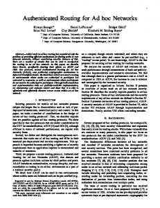
Figure 1. Illustration of DIR receives a RERR from sA D : Node A broadcasts a RERR, and it sends a RREQ for D (Section 2.3.1) if node A is an active source of data packets for D or is performing a localized route repair operation. 2.3.6 Reseting feasible distances A node can safely set its feasible distance to ∞ when it A has an invalid route and the set of predecessors P SD = φ. One approach to ensure the predecessor set is empty is notify each predecessor with a reliable route error update. However, this is expensive in a wireless network with a contention-based MAC protocol. A node broadcasts a route error (RERR) unreliably to notify its predecessors. The unreliable transmissions of RERRs, together with queueing delays for data packets, can cause route lifetimes to be refreshed although no data packets are delivered. This can result in a node invalidating its route, while the predecessors still have a valid route (because the broadcast route error was lost). A node increasing its feasible distance by incorrectly judging the predecessors set as empty can lead to the formation of loops. Accordingly, route and predecessor lifetimes are updated in DIR using the following rules: Node A having an active route to destination D with next hop B upA ) only if it receives an acdates the route lifetime (ttlD knowledgement from the lower layer for the delivery of A to expire the data packet to B. Node A sets maxlif eP SD active route timeout from current time, when it receives A a data packet from any predecessor in P SD . Following these rules when updating the lifetimes will ensure that the routes expire at a node and its predecessors A at the same instant. If maxlif eP SD expires without any A A data packets from P SD , then P SD ← φ and if dA D = ∞ then node A sets f dA D ← ∞.
3 DIR Example Figure 1 shows a directed acyclic successor graph for destination D for a six-node network. Nodes A and B have
active flows for destination D. The feasible/measured distances are shown at time t1 after the initial route setup for destination D. At time t > t1 , link BC fails and node B broadcasts a route error notifying A that D is unreachable. However, A does not receive the route error. Node B initiates a new RREQ with mf dreq D = 2 because B = φ. = 2 and and cannot set it to ∞ until P SD it has f dB D Nodes E and F do not possess any knowledge of destination D and cannot satisfy SDC. They relay the RREQ with req req maxf dD path.F = 2 and maxf dD path.E = 2, respectively. The RREQ reaches the destination D because no node satisfies SDC. At the destination D, a RREP is initirep ated with drep D , f dD ← 0, which follows the reverse path. F Node F updates its hop count dF D ← 1, sets f dD ← 1, and relays the reply to node E. Node E updates distance dE D ← 2, sets f dE ← 2. Node B processes the reply and updates D B its distance dB D ← 3, and sets its feasible distance f dD ← 2 reppath.B B B = 2, dD = 3)). Notice (as min(f dD = 2, maxf dD that the feasible distances are monotonically non-increasing towards the destination D along a path. If A does not receive a RERR for destination D after the new route is setup at B, node A can still forward data packets through B for destination D, and with the ordering maintained no loops would form. On the other hand, if A had received the RERR, it would have issued a new RREQ (A, IDA ) to setup a route to the destination.
4 Performance We present results for DIR over varying loads and mobility. The protocols used for comparison are two on demand protocols DSR and AODV, which reflect the state of the art in on-demand routing, and OLSR which is a pro-active link state protocol. Simulations are run in Qualnet. The parameters are set as in [10]. We use an optimization in DIR, sending directed route requests (DRREQs) which are calculated from the collected path information carried in control messages by using a path selection algorithm (i.e., Dijkstra). The DRREQs contain a source route along which they are routed. If the DRREQ path is not valid then a normal RREQ is flooded on the next attempt after the request timer expires. Otherwise intermediate nodes satisfying SDC or the destination can generate a RREP if they receive a DRREQ. Simulations are performed on two scenarios, (i) 50-node network with terrain dimensions of 1500m x 300m, (ii) 100node network with terrain dimensions of 2200m x 600m. Traffic loads are CBR sources with a data packet size of 512 bytes at 4 packets per second. Load is varied by using 10 flows and 30 flows. The MAC layer used is 802.11 with a transmission range of 275m and throughput 2 Mbps. The simulation is run for 900 seconds. Node velocity is set between 1 m/s and 20 m/s. Flows have a mean length of 100 seconds, distributed exponentially. Each combination
(number of nodes, traffic flows, scenario , routing protocol and pause time) is repeated for 9 trials using different random seeds. We present four metrics. Delivery ratio is the ratio of the packets delivered per client/server CBR flow. Latency is the end to end delay measured for the data packets reaching the server from the client. The network load is the total number of control packets (RREQ, RREP, RERR, Hello, TC etc) divided by the received data packets. Data hops is the number of hops traversed by each data packet (including initiating and forwarding) divided by the total received packets in the network. This metric takes into account packets dropped due to forwarding along incorrect paths. A higher data hops metric indicates more number of hops data packets traverse without reaching the destination or the in-optimality of the routes. Table 2 and 3 summarizes the results of the different metrics by averaging over all pause times for the 50 and 100 node networks. The columns show the mean value and 95% confidence interval. Figs 2, 3, 4, and 5 show the delivery ratio. Confidence intervals(95%) are shown with vertical bars in the graphs. DIR has a very consistent performance across all scenarios and outperforms other protocols in most cases. The exception is at high flows, low mobility scenarios where OLSR and DSR seem to do better. In the low-load 10-flow scenarios, DIR has the highest data delivery although in the 50-node scenario AODV’s delivery is statistically equivalent(confidence intervals overlap). The next best protocol in terms of data delivery is DSR, followed by OLSR. The lowest latency is OLSR at .0129 ± .00 followed by DIR at .0159 ± .00. Significant control overhead is incurred by OLSR and DSR, whereas both AODV and DSR are statistically equal. In the high-load 50-node 30-flow scenario, DIR and OLSR exhibit statistically equal packet delivery. Both DIR and AODV seem to suffer significantly in these scenarios. The low mobility scenarios tend to be over-bound with network partitions and on-demand protocols would attempt to find a route to destinations that are not reachable. This also accounts for the increased network load of these two protocols in this configuration. In practise, an external measure needs to be imposed to avoid excessive attempts to find unreachable destinations. DIR dominates the lowload, 100-node, 10-flow scenarios with the highest packet delivery at .9917 ± .00, the lowest latency 0.0316 ± .00 and lowest network load at 0.7598 ± .09. The next best performance is exhibited by AODV followed by DSR and OLSR. The same trend follows in the high load 100-node 30-flow scenario with DIR dominating, although incurring a bit more control overhead.
All routing protocols forward a comparable number of data packets as indicated by the data-hops metric. The high packet delivery ratio of DIR across all scenarios indicates the correctness of the routes used for forwarding.
5 Conclusion We have presented the Dynamic Incremental Routing (DIR) protocol for mobile wireless ad hoc networks. DIR achieves instantaneous loop freedom by maintaining a strict ordering of feasible distances towards the destination. DIR avoids using timestamps/sequence numbers as an invariant for loop freedom, eliminating the need for globally synchronized clocks or the necessity for a sequence number reset. The results of simulation experiments comparing DIR with DSR, AODV and OLSR using Qualnet show that DIR achieves better performance than the other protocols while ensuring loop-free incremental routing.
References [1] T. Clausen and P. Jacquet, “Optimized Link State Routing Protocol,” Request for Comments 3626, October 2003. [2] E. M. Gafni and D. P. Bertsekas, “Distributed Algorithms for Generating Loop-Free Routes in Networks with Frequently Changing Topology,” IEEE Trans. Comm., COM-29(1):11– 18, Jan. 1981. [3] J. J. Garcia-Lunes-Aceves, “Loop-Free Routing Using Diffusing Computations,” Proc. IEEE/ACM Trans. Networking, 1(1):130–41, Feb. 1993. [4] J. J. Garcia-Luna-Aceves, M. Mosko and C. Perkins, “A New Approach to On-Demand Loop-Free Routing in Ad Hoc Networks,” Proc. PODC 2003, pp. 53-62, Boston, Massachusetts, July 13–16, 2003. [5] J. J. Garcia-Luna-Aceves and M. Spohn, “Source-Tree Routing in Wireless Networks,” Proc. IEEE ICNP’99, pp. 273– 82, Toronto, Canada, October 31–November 3, 1999. [6] D. Johnson et al, “The Dynamic Source Routing Protocol for Mobile Ad Hoc Networks (DSR),” IETF Internet draft, draft-ietf-manet-dsr-09.txt, April 2003. [7] R. Ogier et al., “Topology Dissemination Based on ReversePath Forwarding (TBRPF),”Request for Comments 3684, February 2004. [8] V. D. Park and M. S. Corson. A highly adaptive distributed routing algorithm for mobile wireless networks. In IEEE INFOCOM, pp. 1405–13 vol.3, Apr. 1997. [9] C. Perkins et al., “Ad hoc On-Demand Distance Vector (AODV) Routing,” Request for Comments 3561, July 2003. [10] C. Perkins et al. “Performance Comparison of Two Ondemand Routing Protocols for Ad Hoc Networks,” IEEE Personal Communications, 8(1):16 – 28, Feb 2001.
0.95
1
0.9
0.95
Packet Delivery ratio
Packet Delivery ratio
0.85
0.9
0.85
0.8
0.75
0.7
0.65
0.8 AODV DIR DSR OLSR
AODV DIR DSR OLSR
0.6
0.55
0.75
0
50 100
200
300 500 Pause Time (Secs)
700
0
900
50 100
200
300 500 Pause Time (Secs)
700
900
Figure 2. Delivery 50-nodes, 10-flow,
Figure 3. Delivery 50-nodes, 30-flow,
40pps
120pps
1.05
0.9
1
0.85
0.8 0.95
Packet Delivery ratio
Packet Delivery ratio
0.75 0.9
0.85
0.8
0.7
0.65
0.6 0.75 0.55 AODV DIR DSR OLSR
0.7
0.65
0
50 100
200
300 500 Pause Time (Secs)
700
900
AODV DIR DSR OLSR
0.5
0.45
0
50 100
200
300 500 Pause Time (Secs)
700
900
Figure 4. Delivery 100-nodes, 10-flow,
Figure 5. Delivery 100-nodes, 30-flow,
40pps
120pps
Table 2. Performance average over all pause times for 50 nodes network protocol DIR DSR OLSR AODV DIR DSR OLSR AODV
flows 10 10 10 10 30 30 30 30
delivery ratio 0.9963±0.0006 0.9441±0.0096 0.8894±0.0163 0.9946±0.0010 0.8147±0.0203 0.6987±0.0236 0.7938±0.0137 0.7794±0.0186
latency (sec) 0.0159±0.0009 0.0323±0.0120 0.0129±0.0005 0.0170±0.0010 0.7088±0.1261 4.1535±0.4357 0.8202±0.1138 0.8818±0.1177
net load 0.2237±0.0220 1.7023±0.2986 2.5773±0.1138 0.2489±0.0248 2.4349±0.3294 1.5269±0.1919 0.9666±0.0373 3.7867±0.3613
Data Hops 2.6748±0.0723 1.6974±0.0732 2.5199±0.0705 2.5988±0.0699 2.8901±0.0980 1.9703±0.0851 2.5845±0.0584 2.9148±0.1043
Table 3. DIR: Performance average over all pause times for 100 nodes network protocol DIR DSR OLSR AODV DIR DSR OLSR AODV
flows 10 10 10 10 30 30 30 30
delivery ratio 0.9917±0.0015 0.8959±0.0194 0.8367±0.0278 0.9886±0.0018 0.6781±0.0222 0.6293±0.0216 0.6386±0.0191 0.6492±0.0202
latency (sec) 0.0316±0.0020 0.0895±0.0430 0.0224±0.0008 0.0408±0.0042 0.9355±0.0968 4.8421±0.3578 3.1952±0.3234 1.2072±0.1636
net load 0.7598±0.0975 6.8503±1.1625 15.1404±0.8074 0.8679±0.1009 8.0876±0.8231 5.5590±0.6150 6.6386±0.3159 19.1426±7.6063
Data Hops 3.9550±0.1193 3.3228±0.1446 3.6827±0.1116 3.8248±0.1156 4.5671±0.1640 4.0882±0.1566 3.9999±0.1216 4.5460±0.1617