project under title RPC-HVTS-DCS, to the DAAD for funding the exchange student program between. Beihang University and Paderborn University, as well as ...
Thermal-Electrical Modeling and Simulation of Resonantly Operated DC-DC Converters Based on Extended Describing Function Method Jianxun Lv1, 2, Zhiyu Cao1, Norbert Fröhleke1, Joachim Böcker 1, Haiwen Yuan2, Hanguang Mi1, 2 1 2 Paderborn University Beihang University Power Electronics and Electrical Drives Automation Science and Electrical D-33095 Paderborn, Germany Engineering Phone: +49-5251-60-3413 100191 Beijing, China E-Mail: {cao, froehleke, Phone: +86-01082338697 boecker}@lea.upb.de E-Mail: {pifubhu, yhw}@asee.buaa.edu.cn URL: http://wwwlea.upb.de URL: http://www.buaa.edu.cn
Acknowledgements Thanks belong to the European Commission Seventh Framework Programme (FP7) for funding this project under title RPC-HVTS-DCS, to the DAAD for funding the exchange student program between Beihang University and Paderborn University, as well as all project partners.
Keywords « Resonant converter », « DC power supply », « Simulation », « Modeling »
Abstract Due to the very large difference between electrical and thermal time constants, stimulation for resonantly operated DC-DC converters using physical or ideal switching model is very time-consuming or impossible with limited computational resources. In order to overcome this problem a novel thermal-electrical averaging model of resonantly operated DC-DC converters is proposed in this contribution. The electrical model is based on extended describing function method. All required parameters for the thermal model can be obtained from datasheets. As examples thermal-electrical models of series-parallel resonant converters with LC- and C-type output filters are given and verified by comparison with a standard simulation tool. The thermal-electrical modeling procedure proposed in this contribution can of course also be applied for other types of resonant converters.
1 Introduction In order to save time and cost, simulations are widely used in power electronics circuit analysis and become significantly more important. Deducing the electrical and thermal stress as well as simulating crucial transients are major issues before a decision is taken for a certain circuit topology out of qualified set of circuits. From the viewpoint of modeling depth, the state-of-the-art simulation tools and methods can roughly be divided into three levels:
Physical model-based simulation, e.g. SPICE, SABER, SIMPLORER, etc. Ideal switch model-based simulation, e.g. PLECS, etc. Average model-based simulation, e.g. state-space averaging with PWM converters, generalized averaging and extended describing function model for resonant converter, etc. Since in physical model-based simulations the power electronic devices are modeled to resemble the physical structure as close as required, they provide the most accurate simulation results in both on/off-states and commutation transients. However, this kind of simulation is very time-consuming, especially in simulating power electronic systems with high switching frequency. In ideal switch model-based simulations the commutation transients are neglected. By recording the junction temperature, the voltage across the semiconductor component and the switched current, the switching losses can be deduced using look-up tables. The required information for such a table (e.g. Eon versus uoff, ion and Tj) can be extracted from the semiconductor datasheets or via measurements. In case of resonant converters switching frequencies from some 10 kHz to 1 MHz [1] represent the state of the art. Due to the large time constant of the thermal subsystem (e.g. up to some seconds) relatively long simulation times are required, if the thermal-electrical behaviors of resonant converters need to be simulated at system level, particularly when analyzing detailed load cycles. In this case even the ideal switch model-based simulation is getting very time-consuming or impossible with limited computational resources. In order to get independent of the single switching events and to gain high simulation speed, averaging thermal-electrical models should be used. In [2] calculation of switching losses based on averaged switching modeling for pulse-width modulation (PWM) converters is discussed. Thermal-electrical simulation for resonant converters based on average models is not yet discussed in state-of-the-art publications. In this contribution a general procedure of thermal-electrical average modeling for resonant converter is introduced as follows: While Section 2 gives a short review of the electrical modeling of resonant converters, Section 3 focuses on the computation of semiconductor losses and the thermal model. As examples, the thermal-electrical average models of series-parallel resonant converters (SPRC) with LC- and C-type output filters are developed and verified by comparison with a standard state-of-the-art simulation in Section 4. A final conclusion is drawn in Section 5.
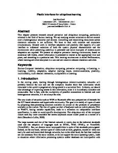
2 Electrical Model As illustrated in Fig. 1, a resonant converter comprises in general of five building blocks: inverter, resonant tank, transformer, rectifier and output filter. The electrical behavior of such system can be described by generalized averaging [3] or extended describing function (EDF) method [4-6]. With the EDF method, the modeling procedure outline of the electrical part is as follows:
Fig. 1: General structure of resonant converters
a. Time-variant nonlinear state equations: State equations can be easily obtained via constitutive equations and Kirchhoff's circuit laws for each time interval. b. Harmonic approach: The nearly sinusoidal current and voltage waveforms of the resonant tank are approximated by their fundamental components while current and voltage of the output filter are approximated by their DC terms. c. Extended describing function: Using the EDF method, the discontinuous terms mentioned in (a) are approximated by their fundamental or DC terms. d. Harmonic balance: Substituting the quasi-sinusoidal terms and the nonlinear discontinuous terms of the nonlinear state equations with their fundamental or DC terms deduced in (b) and (c) respectively, and equating the coefficients of DC, sine, and cosine terms respectively, continuous state equations are obtained, i.e an approximated large-signal model.
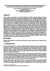
Fig. 2: Series-parallel resonant converter with (a) LC output filter (b) C output filter If the series-parallel resonant converter makes use of a LC output filter (SRPC-LC) (Fig. 2a) and operates in continuous voltage mode (CVM), its electrical large-signal model can be described by a set of non-linear ordinary differential equations (ODEs) by means of EDF method introduced in [5]: d 4 (1) 2 d (2)
0 d d d d
d ,
,
,
where
||
and
4 1
d d
4 1
(5)
,
(6)
,
,
2
,
1
,
d
,
(4)
d d
,
d
(3)
,
,
1
,
,
d ;
,
,
,
,
,
,
(7)
(8)
, vps, vpc are the time-varying
coefficients of the fundamental sine and cosine terms of , and uCp; and are the DC terms of output-filter current and voltage. The subscript “ ” in Lf,p, Cf,p, Rp, rc,p, r´c,p, iLf,p, vcf,p, and i0,p denotes the transformation on the primary side of the transformer. This model shows good precision, if voltage mode (CVM). However, the deviation of this the SPRC-LC is operated in continuous model is relatively large, if it is operated in discontinuous voltage mode (DVM). Since optimization of the electrical large-signal model is not focus of this paper, in order to better demonstrate the proposed novel thermal-electrical model, SPRC-LC in Section 4 is designed to operate in CVM. If a C-type output filter is applied (SPRC-C, Fig. 2b) the electrical large-signal model can be described by the following ODEs by using EDF method discussed in [5] [6]: 1 4
d d
sin
sin 2 /2
2
d d
(9)
1
sin
sin 2
d d d d d
,
d
1
1
arccos
(10)
1
(11)
1
(12) (13)
cos
,
2
,
Where
/2
,
,
(14)
1
.
Similarly, the electrical behaviors of other commonly applied resonant converter topologies, e.g. series resonant converter (SRC), parallel resonant converter (PRS), can also be described by non-linear ODEs by means of EDF method.
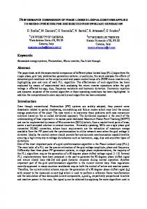
3 Thermal Model The following derivations of the semiconductor thermal model are based on insulated-gate bipolar transistor (IGBT) full-bridge inverter and bridge rectifier. For half-bridge inverter or metal oxide semiconductor field-effect transistor (MOSFET) inverter and other types of rectifiers the semiconductor thermal model can be deduced in a similar way. Inverter conduction losses: In general, the output characteristic of IGBT and forward characteristic of freewheeling diode (FWD) at two or more different temperatures (e.g. at T1 = 25 ° and T2 = 125°) are given in datasheets, which can be linearized and described by using two characteristic values U0(T1/2) and R(T1/2) (see Fig. 3). Using linear interpolation a linearized output characteristic/forward characteristic of IGBT/FWD at the temperature Tj calculated by the thermal model can be obtained by ,
(15)
where
(16)
and
(17)
.
Fig. 3: Linearization of the IGBT output characteristic and forward characteristic of FWD
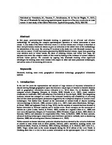
Fig. 4: Typical voltage and current waveforms of resonant converter in inductive (super-resonant) operation mode
The typical voltage and current waveforms of a resonant converter are shown in Fig. 4. Using the above assumptions, conduction losses of IGBT and FWD are obtained as 1 , , 2 (18) ̂
,
,
1 2
1
̂
cos
(19)
, ̂
,
̂
sin 2 2
. 4 The phase shift between the fundamentals of the inverter output voltage and the resonant can be calculated by using AC fundamental analysis according to [5] as current 2
1
cos
arctan
Im Re
(20)
where Zin is the input impedance of the resonant converters, or by the sine and cosine coefficients and of the resonant current in the EDF model arctan
(21)
Inverter switching losses: As shown in Fig. 5, in inductive operation mode (super-resonant) IGBT switch-on and FWD switch-off are soft switching actions, while the IGBT is hard switched off. In capacitive operation mode (sub-resonant) the switching actions are just vice versa. The hard switching losses are computed using a look-up table. Hard switching losses Eon, Eoff and EFWD,off versus DC voltage, collector current, junction temperature and gate resistance are obtained from datasheets [7] or via measurement [8]. Soft switching losses cannot be obtained from datasheets due to the large variety of influencing parameters. They are either neglected or obtained by measurements. In this contribution the soft switching losses are neglected.
ioff = iˆ sin( π − ϕ )
ion = iˆ sin( −ϕ )
Fig. 5: Calculation of switching losses
Fig. 6: Cauer’s thermal network model
Rectifier losses: Conduction and switching losses of rectifier diodes are computed by using the same method mentioned above. Thermal model: In order to describe the thermal behavior and to calculate the junction temperature of semiconductors Tj, Cauer’s thermal network model is applied (Fig. 6) [9].
4 Application Example and Comparison As example SPRCs with different types of output filters (Fig. 2) are simulated using the proposed model. The SPRC is fed by a rectified three-phase mains with an input line voltage 400 V 10% resulting in 565 V 10% and has an extreme wide operation range of Uout = 0 … Urat and Iout = 0 … Irat (Fig. 7). In order to minimize the deviation caused by the electrical large-signal model and to better demonstrate the novel proposed thermal-electrical model the following non-optimized resonant tank parameters are used in this example: • Resonant tank: LS = 170 μH, CS = 1.49 µF, CP = 745 nF • Transformer: n = 0.3
Fig. 7: Operation range of a 32 kW DC power supply (Urat = 500 V, Irat = 80 A, Prat = 32 kW). OP1…OP9 denote operation points at max. output voltage, while OPa…OPi denote operation points at max. output current.
Fig. 8: Implementation of the proposed thermal-electrical model for a SPRC-LC C By using these parameters the SP PRC is ensured to operate in CVM, if a LC outputt filter is applied. The parameters of IGBT and diodde used in this example: • IGBT: Infineon FF2000R12KS4 (1200 V, 200 A) [10] • Diode: Sonic fast recovvery diode (1200 V, 50 A) [11] As illustrated in Fig. 8 the prroposed thermal-electrical model of the SPRC C is implemented in MATLAB/Simulink. The electrical large-signal model is implemented using an a S-function, which outputs the amplitude of the resoonant current ̂ and the phase shift . The turn--off loss is calculated by using look-up-table (LUT), thhe conduction losses and the thermal model deduuced in Section 3 are implemented in another S-functioon block, with ,
sin π
,
,
φ and
,
(22)
.
(23)
The proposed thermal-electricaal averaging model (TEAM) is compared withh the results of the commercial circuit simulation toool PLECS, in which a thermal-electrical switchiing model (TESM) is applied. The steady-state compaarison of the total semiconductor losses of SPRC C and IGBT junction temperatures at various operationn points (see Fig. 7) are given in Fig. 9 and Fig.. 10, respectively. As examples, the transient compariison of conduction losses of inverter and rectifiier at operation point OPf are given in Fig. 11, and thhe transient comparison of junction temperaturess of IGBT, FWD and rectifier diode of SPRC at OPf arre given in Fig. 12. Comparison results show a goodd agreement between the proposed TEAM and cirrcuit simulation using TESM. Deviations are due to the linearization of output characteristics off IGBT and forward characteristics of FWD as well ass due to the resonant current, which shape differss to some extend from the assumed sinusoidal waveform m in reality.
P/W 2000
Steady-state total semiconductor losses of SPRC-LC
P/W 2000
1500
Steady-state total semiconductor losses of SPRC-C
1500
1000
1000
proposed TEAM TESM-based circuit simulation
500 OPi
OPh OPg
OPf
proposed TEAM TESM-based circuit simulation
500 OPi
OPe OPd
OPh OPg
OPf
OPe OPd
(a) (b) Fig. 9: Comparison of the steady-state total semiconductor losses of (a) SPRC-LC and (b) SPRC-C
T/℃
Steady-state IGBT's junction temperature of SPRC-LC
T/℃
150
150
100
100
50
proposed TEAM TESM-based circuit simulation
0 OPi
OPh
OPg
OPf
OPe
OPd
Steady-state IGBT's junction temperature of SPRC-C
50
proposed TEAM TESM-based circuit simulation
0 OPi
OPh
OPg
OPf
OPe
OPd
(a) (b) Fig. 10: Comparison of steady-state IGBT junction temperature: (a) SPRC-LC and (b) SPRC-C
(a)
(b) Fig. 11: Comparison of transient conduction losses: (a) SRPC-LC and (b) SPRC-C at OPf green: proposed TEAM, red: TESM circuit simulation
(a)
(b) Fig. 12: Comparison of transient junction temperatures of (a) SRPC-LC and (b) SPRC-C at OPf green: proposed TEAM, red: TESM circuit simulation
5 Conclusion and Outlooks In this contribution, a novel thermal-electrical modeling procedure for resonant converter is deduced. By neglecting switching actions, the simulation speed of the novel thermal-electrical model is an order of magnitude higher than that of ideal switching model. This makes it possible to simulate efficiently the thermal-electrical behavior of resonantly operated DC-DC converters at system level. As examples this technique is applied in SPRC with different types of output filters. A comparison between the novel thermal-electrical model and conventional simulation shows good accuracy of the novel approach. The proposed procedure can of course also be applied to other types of resonant converters, e.g. SRC, PRC, etc.
6 References [1] D. Fu, B. Lu and F.C. Lee, F., "1MHz High Efficiency LLC Resonant Converters with Synchronous Rectifier", in Proc. of Power Electronics Specialists Conference, 2007, pp. 2404 - 2410. [2] O. Al-Naseem, R. W. Erickson, and P. Carlin, "Prediction of switching loss variations by averaged switch modeling", in Proc. of Applied Power Electronics Conference and Exposition, 2000, pp. 242-248. [3] S. R. Sanders, J. M. Noworolski, X. Z. Liu and G. C. Verghese, "Generalized averaging method for power conversion circuits", IEEE Transactions on Power Electronics 6(2), 1991, 251-259.
[4] Eric X. Yang, Fred Lee and Milan M. Jovanovic, "Small-Signal modeling of LCC resonant converter", in Proc. of Power Electronics Specialists Conference, 1992, pp. 941-948. [5] J. A. Martin-Ramos, J. Diaz, A.M. Pernia, J.M. Lopera, and F. Nuno, "Dynamic and Steady-State Models for the PRC-LCC Resonant Topology with a Capacitor as Output Filter, " IEEE Trans. on Industrial Electronics , 2007, pp. 2262-2275. [6] Cao, Z.; Hu, M.; Fröhleke, N. and Böcker, J., "Modeling and Control Design for a Very Low-Frequency High-Voltage Test System", IEEE Transactions on Power Electronics 25(2), 1068-1077, 2010. [7] G. Feix, S. Dieckerhoff, J. Allmeling, and J. Schonberger, "Simple methods to calculate IGBT and diode conduction and switching losses", in Proc. of European Conference on Power Electronics and Applications, 2009. [8] S. Munk-Nielsen, L. N. Tutelea, and U. Jaeger, "Simulation with ideal switch models combined with measured loss data provides a good estimate of power loss", in Proc. of Industry Applications Conference, 2000, pp. 2915-2922. [9] M. März and N. Paul, "Thermal Modeling of Power Electronic Systems", in Proc. of PCIM Europe Magazine 2, pp. 20 - 27, 2000. [10] IGBT module FF200R12KS4, Infineon, 2009, http://www.infineon.com/. [11] Sonic fast recovery Diode DHG100×1200NA , Sonic, 2009, http://www.ixys.com/.