36 North Hanover Street,. University of Strathclyde,. Glasgow Gl 2AD, UK. Glasgow Gl 1XH, UK. [colinu, siebert]@turing.ac.uk. [jpm, rjf]@cs.strath.ac.uk. Abstract.
Active Animate Stereo Vision C.W. Urquhart and J.P. Siebert The Turing Institute Limited, George House, 36 North Hanover Street, Glasgow Gl 2AD, UK. [colinu, siebert]@turing.ac.uk
J.P. McDonald and R.J. Fryer Machine Perception Research Group, Department of Computer Science, University of Strathclyde, Glasgow Gl 1XH, UK. [jpm, rjf]@cs.strath.ac.uk
Abstract This paper describes recent research concerning the Active Stereo Probe (ASP) stereo vision system that combines animate oculo-motor reflexes with a novel active illumination source. Two methods for accurate surface recovery from stereo at rates approaching real time are described. Results using texture projection combined with a fast sub-pixel matching algorithm are presented. The development of a high accuracy, fast active ranging technique based upon temporal modulation is also presented. A number of novel extensions are introduced to address this technique's traditional shortfalls and place it in a sound theoretical framework. A calibration regime suitable for incorporating photogrammetric techniques into the ASP active vision system during dynamic system operation is described.
1.
Introduction
The Active Stereo Probe (ASP) project is concerned with both active and anthropomorphic approaches to vision. This paper sets out to describe some of the active vision aspects of the project. Two differing definitions for active vision are evident in the computer vision literature. The utilisation of active illumination or radiant energy is the more established definition; while recent research using actively mobile passive sensors has also been termed active vision. The ASP system contains components of both types of active vision. One of the primary goals of ASP is to develop a stereo vision system applicable in domains such as biostereometrics, reverse engineering, virtual reality, telepresence and symbolic coding for 3D video transmission purposes. We believe that real success in these application areas is critically dependent on the recovery of accurate threedimensional surface models at rates approaching "real-time". It is also our belief that such a system will require the flexibility provided by animate viewpoint control and vision based sensor control reflexes if its performance is not to be crippled by constraints on scene content and the viewpoint of the cameras. Recent advances in Liquid Crystal light valve technology have made viable the use of non-coherent structured illumination sources that allow fast, accurate and flexible structured light approaches to the acquisition of 3D data from close range photogrammetry. In order to exploit this Liquid Crystal technology within the ASP project, a state-of-the-art Active Illumination Projection System utilising a high contrast, high resolution, Liquid Crystal Spatial Light Modulator has been developed. This also serves as a flexible test bed for determining optimal pattern generation and projection characteristics.
BMVC 1993 doi:10.5244/C.7.8
76 Within the Active Stereo Probe project two complementary approaches to the stereo-correspondence problem have been investigated: texture enhanced stereo and stereo scene coding. Texture enhanced stereo traditionally offers high accuracy but is computationally expensive. In contrast, temporal modulation, on which stereo scene coding is based, is widely recognised as being quicker but less accurate.
2.
System Configuration
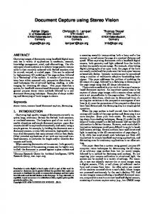
The basic configuration of the sensor head portion of the ASP system is shown in figure 2.1. The sensor head consists of a stereo-pair of cameras independently actuated in elevation and azimuth to support a range of oculo-motor reflexes such as vergence and saccadic gaze control. The active illumination source is positioned below the sensor head such that it projects onto the mirror which is situated between the cameras. The mirror is also actuated in elevation and azimuth allowing the reflected structured illumination pattern to be steered so that it is maintained within the cameras' fields of view.
Head Base-Plane Gantry
Right Actuated Camera
Actuated Left Actuated Projection Mirror Camera
Figure 2.1: The ASP sensor head.
3.
Modelling and Characterisation
The incorporation of viewpoint control in the sensing system brings the requirement for dynamic calibration. Our approach to this is critically dependent on the accuracy of the positional feedback of the camera actuators and the mechanical stability of the entire system. Consequently, the system has been developed from the outset to meet a specified set of design and performance criteria using a mathematical model of the system's imaging geometry and kinematics. Simulation experiments were carried out for candidate designs to ensure that the parameters of external orientation could be derived with sufficient accuracy from actuator feedback [1]. Prior to construction, detailed geometric modelling of the proposed projection optics was also conducted to investigate positional parameter sensitivity and the spatial relationship between projected and imaged pixels. An actuation system was designed that ensured projection accuracy equivalent to that achieved by the ASP cameras and a lens arrangement was designed that maximised overlapping working volumes of projection and image and minimised loss of usable projection spatial frequency bandwidth.
77
After construction, detailed characterisation of operational performance was undertaken. This addressed issues not easily investigated using the developed geometric model (e.g. the relationship between the system modulation transfer function (MTF) and projection distance) but important to determine attainable operating performance. Figure 2.1 also shows the completed sensor head. Backlash free DC motor driven rotational actuators with a resolution of 0.6 arcsec and specified maximum axial deviation of 1.5 arcsec have been used. Precisely engineered brackets (with dimensions accurate to approximately 0.002" «• 50um) have been machined to form the basis of each of the actuated camera (and projection mirror) sub-assemblies, and a length of high rigidity optical bench has been adopted as the head base-plane.
4.
Texture Enhanced Stereo
4.1 Approach Our objective is to achieve accurate stereo-based surface recovery by incorporating photogrammetric principles into an active robot vision system featuring steerable CCD cameras. Actively illuminating the scene and subsequently matching captured stereogrammes using the Multi-Scale Signal Matcher (MSSM) [2] provides dense and accurate disparity data. Unfortunately, conventional photogrammetric techniques, such as bundle adjustment, are highly computationally expensive due to the extent of the required system parameter search space. Furthermore, these techniques rely heavily upon the availability of accurately measured ground control points on imaged objects. Consequently these techniques are clearly unsuitable for use in the context of a realtime active vision system such as ASP. In order to address the above limitations, we are currently investigating the following two-stage approach to calibration. Prior to dynamic system operation, static calibration is carried out using conventional photogrammetry by imaging an array of calibrated ground control points. This establishes an accurate initial measurement of system parameters. Thereafter, dynamic calibration is maintained following each camera movement by updating the external calibration parameters using information provided by encoder feedback. We propose to utilise this dynamically updated initial measurement to heavily constrain the search space required to fit the photogrammetric model to the newly imaged data. This is made possible due to the available encoder resolution (of the order of 0.6 arcsec). In this way we expect to achieve a usable level of performance by substantially reducing the execution time of conventional photogrammetric algorithms.
4.2 Stereo Matching The MSSM algorithm is a scale-space correlation based stereo-matcher which provides dense disparity information to sub-pixel accuracy. In the past, stereo-matching algorithms of this kind have tended to be extremely computationally expensive. However, by couching the latest version of the algorithm in terms of image pyramids, execution times approaching real-time are now achievable (see table 4.1). The accuracy performance of MSSM has been extensively analysed for random-dot stereogrammes. It can be seen from figure 4.1 that a RMS disparity error of approximately 0.1 pixels is achievable by MSSM for synthetic stereogrammes.
78
Image Size (pixels)
128x128
256x256
512x512
576x768
IBM RS6000 320H
3.8s
15.5s
64.5s
104.6s
Sun SPARCstation LX
8.4s
32.7s
130.9s
215.0s
Table 4.1: Typical execution times, in seconds, for 2D stereo matching using MSSM on IBM RS6000 and Sun SPARCstation LX workstations. (ID stereo matching is approximately 40% quicker.)
5 4 3
3
2
SNRi-lOdB:
~/~\
\
I
8 1 & fr 0 3
\
\
-
-2 -3
\
I
i
i -
-4 -5 32
48 64 80 96 Column Position (pixels)
112
5
10 15 20 Imagt Signal/Noise (dB)
Figure 4.1: Stereo-matching accuracy achieved by MSSM for a typical random-dot stereogramme. By projecting randomly textured light onto the scene under investigation, a level of accuracy approaching that achieved for random-dot stereogrammes is possible. Figure 4.2 shows a stereogramme captured while the subject was illuminated with textured light. A non-textured (naturally illuminated) image which was captured immediately afterwards is also shown. A surface model of the scene is obtained by matching the texture projected stereogramme using MSSM and back-projecting the matched image points into three-dimensions. Such a surface model is shown in figure 4.3 after it has been vertex shaded, Gouraud shaded and rendered (surface "draped") with the naturally illuminated view of figure 4.2.
Texture-projected stereogramme.
Naturally illuminated image.
Figure 4.2: Captured images.
79
Vertex shaded.
Gouraud shaded.
Rendered.
Figure 4.3: Recovered surface model.
4.3 Calibration
Figure 4.4: The calibration grid. We have constructed a calibration grid comprising a matrix of precisely machined cylinders of different lengths (see figure 4.4). The grid has been measured so that the 3D positions of the circular ends of the cylinders are known to an accuracy of ±5.0{Jm. The centres of the measured cylinder ends are treated as the ground control points and their image locations are detected fully automatically using an implementation of Cumani et. al.'s contour following method [3]. Simulation experiments have shown that this method can determine the centre of circular contours with an RMS error of about 0.01 pixels. After target detection, static calibration is carried out using the measured 3D positions and the derived image co-ordinates of the centres of the target circles. We have implemented a version of the Direct Linear Transform (DLT) [4] which we are currently using for both static calibration and surface recovery. Equations 4.1 show the simplest form of the DLT in which {x, y, z) are the world co-ordinates of a point, (u, v) are its image co-ordinates and Pi, P2 P11 are the system parameters to be calibrated. u=
(4.1)
80
5.
Stereo Scene Coding
5.1
Approach
Temporal Modulation was chosen for investigation because it promises dense range elucidation at low processing cost. However, published methods of temporal modulation signal interpretation do not realise the full accuracy potential of this technique. Most reported schemes simply threshold images to determine whether pattern elements originated from a white or a dark area in a given projection. In [5] this thresh-holding is aided using a reference image generated from a full on projection and in [6] is aided by the average of a full on and a full off projection. A low resolution nematic liquid crystal is used in [7]. Here the inverse of each pattern is also projected and the transitional direction used to determine projected pixel state. However these techniques only form correspondences between projected and imaged pixels which places a strict limit on maximum attainable measurement precision and accuracy. This is acknowledged in [8] and partially addressed in [9] where image pixels close to estimated projection boundaries are chosen for correspondence in preference to other image pixels. We have developed a three phase mechanism to improve pattern interpretation and address these shortfalls.
5.2 Boundary Location and Interpolation Instead of forming correspondences between pixels we form correspondences between projected pattern boundaries and sub-pixel located points in the images at each level of projection. This improves dramatically the potential precision of the depth measurements made. A directionally tuned operator is applied at each level, appropriately sized to the expected region width. The first 3 frames of an example input sequence, projected using the ASP Active Illumination Projection System in daylight conditions onto a mannequin head, is shown in figure S.I (a). A slice of the response to the tuned edge operator for each input frame is shown in figure 5.1 (b). The peaks corresponding to pattern transitions at each level are easily detectable. Various interpolation methods for sub-pixel pattern-edge location have been evaluated. A simple linear interpolator was found to best fit the edge operator response predicted by the ASP system MTF. The choice of a linear interpolator was verified using an empirical model of the edge operator response determined for the stripe width at each scale.
5.3 Divide and Conquer in Scale Space To improve robustness and ease of processing, the images are successively partitioned depending on the region boundary locations found at previous levels. This process can be well characterised since the projected pattern is well understood and only one new region boundary per partition will exist. This divide and conquer approach has been extended to a complete scale space architecture to reduce computational expense and further improve operational robustness. For each projected pattern, the edge operator is applied to trace down a scale space pyramid built from the full sequence of imaged frames, appropriately sampled at each level. This can be illustrated by again considering figure 5.1. In the scale space implementation a coarse estimate for the region boundary in the first frame of 5.1 (a) is made (since the edge operator size is large and the image will be coarsely sampled). However the response at the next level (where the sample frequency is
81
doubled and the operator size is halved) yields a much better estimate (corresponding to the minimum in the edge operator response for the second frame in 5.1 (b)). Hence we improve our initial estimates by tracing and refining boundary locations at each subsequent level of the scale space pyramid built from the input image sequence.
(a) input sequence
(b) edge operator response Figure 5.1 : Processing Stages, where (a) is the first three input frames and (b) the horizontal slices through the image centres showing the unsampled response (for display) to the tuned edge operator
5.4 Stereo Instead of attempting to calibrate the projection system we utilise the calibration techniques described previously for the ASP cameras. Essentially the above procedure is followed independently for each camera. This results in a mapping between each projected LCD pixel boundary and points in both cameras. Therefore the technique has uniquely coded the scene and implicitly solved the stereo correspondence problem. This eliminates the projection optics from all calibration and measurement calculations.
5.5 Results The full stereo scene coding technique described has been implemented and evaluated on various scenes. The results shown below illustrate the quality attainable for the mannequin's head introduced earlier. A 7 frame sequence was projected and captured with the mannequin approximately 3m from the ASP system. A vertical slice through
82
the resulting disparity map is graphed in figure 5.2. It is important to note that no surface reconstruction or smoothing has been performed on the data shown. The graph shows the raw disparity output from the algorithm. Figure 5.3 shows two models built from the disparity map used for figure 5.2.
Figure 5.2: Stereo scene coding derived disparity against row position for the mannequin. This vertical slice corresponds to the central column of the disparity map. The forehead, nose, lips and chin have been cleanly and accurately recovered without requiring disparity smoothing.
400 -
-30
-20 -10 0 Disparity (pixels)
Vertex shaded.
Gouraud shaded.
Figure 5.3: Mannequin Surface Model.
5.6 Accuracy The results appear visibly better than other reported implementations and a formal analysis of the accuracy and robustness of the technique is currently underway. Initial analysis indicates that using linear interpolation (for boundary location) and no surface reconstruction the system can resolve depth differences of 0.5mm at 3m with noise
83
levels on the disparity/depth data producing range errors of approximately ±0.25mm at the same distance.
6.
Conclusions
The aim of the ASP project is accurate "real-time" surface recovery from stereo. We have developed two approaches to stereo correspondence: texture enhanced stereo and stereo scene coding. Traditionally neither of theses techniques offer the combination of speed and accuracy required for our perceived applications. Our developments have addressed these shortcomings and have resulted in a significant increase in the performance of both techniques. We have demonstrated that both the required speed and accuracy are realistically attainable using either technique. We have shown that the MSSM stereo-matching algorithm more than adequately addresses the requirement for dense, sub-pixel disparity estimation. By couching the newest version of this algorithm in terms of image pyramids, execution times approaching those required for "real-time" operation are now achievable without loss of match accuracy. We have described a calibration regime which uses encoder feedback to track camera exterior orientation during dynamic operation. This will allow the use of highly accurate photogrammetric calibration techniques which would otherwise be prohibitively computationally expensive for practical active vision. An new implementation of the temporal modulation active range finding algorithm has been developed and demonstrated. This improves on many previous weaknesses of the approach, not least by allowing sub-pixel measurements to be used in surface reconstruction. Its basic simplicity and minimal computational requirements make it a prime candidate for many industrial tasks requiring data on surface shape. Our approach to calibration is to incorporate photogrammetric principles into a rigorously designed active robot vision system. A version of the DLT has been implemented for the first stage of static calibration. This has already been integrated with the texture enhanced stereo scheme. Initial experiments indicate an achievable accuracy of the order of ±0.2mm RMS in planimetry and ±0.5mm RMS in height for 3m range. We are currently integrating this stage of the calibration process with the stereo scene coding scheme which will allow direct comparison of algorithm performance with texture enhanced stereo. The second stage, required to maintain calibration during dynamic system operation is nearing completion.
7.
Acknowledgements
This work is part supported by the DTI and SERC under the Active Stereo Probe project IED3/1/2109. The calibration grid was kindly constructed and measured by the Manufacturing and Engineering Management Division of the University of Strathclyde, for which the authors would like to thank Gordon Mair, Alex Harvey and the technicians there. The authors gratefully acknowledge David Wilson, John Heng, Peter Mowforth, Arthur van Hoff and Patrick Vorgers for their helpful contributions to this work.
84
8.
References
1.
Urquhart, C.W. and Siebert, J.P. Development of a Precision Active Stereo System. In Proceedings of the IEEE International Symposium on Intelligent Control, Glasgow, Scotland, August 1992, pp. 354-359.
2.
Jin, Z.P. and Mowforth, P.H., "A Discrete Approach to Signal Matching", Glasgow, Scotland, January 1989.
3.
Cumani, A. et. al. High Accuracy Localization of Calibration Points for Dimensional Measurements by Image Processing Techniques. In Proceedings of the Fifth International Conference on Advanced Robotics, Pisa, Italy, 18-22 June 1991, pp. 1761-1765.
4.
Abdel-Aziz, Y.F. and Karara, N.M. Direct Linear Transformation from Comparator Coordinates into Object Coordinates in Close-Range Photogrammetry. In Proceedings of the ASP Symposium on Close-Range Photogrammetry, Illinois, USA, January 1971, pp. 1-18.
5.
Inokuchi, S., Sato, K., and Matsuda, F. Range Imaging System For 3-D Object Recognition. In Proceedings of the 7th International Conference on Pattern Recognition, 1984, pp. 806:808.
6.
Sato, K. and Inokuchi, S. Three-Dimensional Surface Measurements by Space Encoding Range Imaging. Journal of Robotic Systems 2, 1 (1985), 27-39.
7.
Sato, K. and Inokuchi, S. Range-Imaging System Utilising Nematic Liquid Crystal Mask. In 1st International Conference on Computer Vision, June 1987, pp. 657-661.
8.
Stahs, T.G. and Wahl, F.M. Fast and robust data acquisition in a low cost environment. In : ISPRS Symposium : Close Range Photogrammetry Meets Machine Vision, ETH Zurich, Switzerland, 1990.
9.
Gutsche, R., Stahs, T., and Wahl, F.M. Path Generation with a Universal 3D Sensor. In Robotics and Automation : Proceedings of the 1991 IEEE Conference, IEEE Computer Society Press, Sacramento, CA., 1991, pp. 838843.