compatible with any J2EE implementation and the applications developed ..... J2EE is the Sun Microsystems solution for enterprise application development.
An Experience in Architectural Extensions: Active Objects in J2EE Paola Inverardi, Fabio Mancinelli, Henry Muccini, and Patrizio Pelliccione University of L’Aquila, Computer Science Department Via Vetoio 1, 67010 L’Aquila, Italy {inverard,mancinel,muccini,pellicci}@di.univaq.it
Abstract. In this paper we present an experience in architectural extension. The goal of our project was to provide Active Objects in the Java 2 Enterprise Edition (J2EE) reference architecture by suitable extensions that should not violate the architectural J2EE principles. Our approach to the problem was rather formal. We first formalized the notion of Active Object, the basic characteristics of the J2EE model and its component model Enterprise JavaBeans (EJB). Then, driven by the peculiar characteristics of an active object, we investigated several possible architectural extensions. The solutions were formalized as well and their consistency with the J2EE model was validated by using model checking techniques. In this way we discovered that only one of them was acceptable. The whole formalization and validation has been carried out by using the Charmy environment. In Charmy the architectural formalization makes use of diagrammatic notations, Scenarios and State Diagrams, and SPIN is the target model checking engine.
1
INTRODUCTION
In this paper we present an experience in architectural extension. A company asked us to evaluate the possibility to extend the Java 2 Enterprise Edition (J2EE) [18] reference architecture model, and therefore its component model Enterprise JavaBeans (EJB) [14], with Active Objects (AOs) in order to guarantee asynchronous method1 invocation. The extension should not violate the architectural J2EE principles. Moreover we had some requirements to meet, i.e. the extension should be compatible with any J2EE implementation and the applications developed with it should be compatible with any J2EE implementation. The former means that the extension has to be compatible with earlier versions of EJB while the latter means that we could not use any implementation specific features to realize it. We approached the problem in a rather formal way. First, we formalized the notion of Active Object, the basic characteristics of the J2EE and EJB model. Then, driven by the peculiar characteristics of an Active Object, we investigated several possible architectural extensions. The solutions were formalized as 1
in the following, terms “method” and “service” will be used interchangeably.
2
Paola Inverardi et al.
well and their consistency with the J2EE model was validated by using model checking techniques. In this way we discovered the one that was acceptable. The whole formalization and validation was carried out by using the Charmy [7] environment. In Charmy the architectural formalization makes use of diagrammatic notations, Scenarios and State Diagrams, and SPIN [20] is the target model checking engine. As a result of this work we realized that the approach we followed could actually be generalized and used to support evolutions (extensions/refinements) in software architecture. We have also applied the whole approach to EJB2.0 by proposing a new extension which uses its new features. This represented a way to validate the approach and a way to compare the two extensions. Summarizing, the contributions of the paper are the proposal of a J2EE architectural extension for Active Objects and an approach (together with a framework) to rigorously support architectural extensions. 1.1
Related works
The paper addresses several topics. On the software architecture side works on architectural refinements [15], architecture evolutions [23], architectural specifications [1] can obviously be related. Another bunch of possible relations is on the conformance checking side, that is which properties and models and which proof techniques. Again to this respect works on analysis [22], model checking [21], graph rewriting [5], view consistency [4] can be certainly relevant. We do not have space here to discuss these possible relations in detail, we just notice that our aim is to show that practical architectural extension problems can be rigorously treated with an acceptable degree of formality and state of the art tools. In the following, we focus on two contributions which are specific of the application domain we are working on, namely J2EE and can more immediately be related with what we have been doing. – In [16], the authors define Promela code modeling EJB1.1 specification, formalizing the informal specification. They use this model for SPIN-standard checks (deadlock-freeness) and they prove that the model does not correctly behave with respect to a selected flow, representing a property of the reference model. This approach is close to the portion of our work in which we formally define the EJB Software Architecture (EJB SA) and prove its correctness with respect to specification properties. To this respect the main difference is that their checks are more fine-grained since their focus is on checking the EJB platform and not on architectural issues. – Since the EJB specification is ambiguous, in [19] the authors use Wright to formally define its software architecture. This model is then submitted to formal analysis via the Failures Divergence Refinement (FDR) model checker founding a deadlock. The focus of the paper is in assessing the need of a formal specification as the “place where the complexity of the specification can lead to errors that might be hard to detect otherwise”.
An Experience in Architectural Extensions: Active Objects in J2EE
3
We agree that i) there is the need to formalize informal specifications; ii) the formal model may be used for analysis via model checking and iii) model checkers may be used for standard analysis (deadlock, constraint violations, livelock and so on) or behavioral checks with respect to LTL formulae. However our approach tries to take a more liberal view in order to extend the support to rigorous reasoning beyond the classical bounds of strict formal reasoning on a model or on pairs of models. First, we do neither require to use a formal architectural language nor to completely specify the architectural descriptions. We try to exploit as much as possible the architectural artifacts, both static and dynamic, that exist in a standard development process. Second, we want to address evolution, that is we want to support extensions, and possibly refinements and thus consistency among different model abstractions. Third we want to show that rigorous reasoning can be supported on suitable portions of the specifications. We show how in practice focus only on the properties and the specification portions relevant to the problem under consideration. The paper is structured as follows. The next section describes, in general terms, the approach to architectural extensions we followed. It constitutes one of the two outcomes of our paper which will be used to present the architectural extensions. In Section 3 the relevant features of the Charmy environment are briefly summarized. Section 4 introduces J2EE, EJB1.1 and AO, and their formalization. Section 5 presents the architectural extensions to obtain AO in EJB1.1 and discusses their validation. In Section 6 EJB2.0 is considered and a different architectural extension is described and validated. Conclusions and future works are reported in Section 7.
2
THE APPROACH: AN OVERVIEW
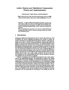
Let us briefly introduce the approach we are going to follow in the rest of the paper. The problem we are going to manage may be outlined as follows (Figure 1). Given a system we assume to have a rigorous high level description of its relevant architectural characteristics. By high level we mean that we do not have an explicit complete model of the system software architecture but only a description of relevant properties. In the terminology of [2] this may correspond to define the reference architecture. In our case we will describe static properties using natural language and static diagrams; dynamic properties, like in other approaches [17, 12], are formalized using Scenarios. This corresponds to level 1 in Figure 1. Starting from this high level specification we can actually build a possible software architecture model encompassing both static (components and connectors) and dynamic (state-based models) information. This is represented in Figure 1 at the second level. Obviously the Software Architecture (SA) specification has to (in some way) conform to the reference architecture, implementing its properties. This conformance checking is denoted by the arrows linking backward the second level to the first. In our case we will use our framework to validate the SA conformance with respect to the behavioral requirements, proving that the SA model behaves (or not behaves) accordingly to the expected properties.
4
Paola Inverardi et al.
S p e c
� � � � � ��� � ���
EJB Specification
Properties formalization Conformance drives Checking
S A
"EJB" Software Architecture
extension E x t e n s i o n
Conformance Checking
AO Specification level1
Properties formalization
drives
Conformance Checking
level2
"AO" Software Architecture
extension
Conformance Checking level3
Extended Software Architecture
Fig. 1. The approach: an overview
Often, for evolutionary purposes architectural models need to be extended or different aspects of the same system must be combined in order to get a more comprehensive model. In any case the enhanced description still has to maintain the high level abstract properties. This situation is depicted in level 3 in Figure 1. The backward arrow, from level 3 to level 1, denotes that conformance checks must be done in order to guarantee the validity of the properties identified in the initial descriptions. In the following we report our experience in extending J2EE with Active Objects. Following the approach outlined above we first analyze the (informal) specification of J2EE and of AO. This allows us to establish the set of static and dynamic properties that constitute the high level architectural specifications of J2EE, EJB, and AO. Then we provide actual architectural models for these high level descriptions and model-check their correctness with respect to the desired properties. Next step is to integrate the two models in a suitable way, so that both the high level properties of J2EE and AO are satisfied by the enhanced architecture. Its conformance is then proved.
3
THE CHARMY FRAMEWORK
This section presents a brief overview of the Charmy (CHecking ARchitectural Model consistencY) framework [8, 9, 7]. The Charmy approach is based on the assumption that state diagrams and scenarios models provide distinct and complementary views of the system. They both represent dynamic aspects, they can be incomplete, in general they are not independent and can specify contradictory or inconsistent behaviors.
An Experience in Architectural Extensions: Active Objects in J2EE Component Q
Component P ?ch1
m1
b
R m5
!ch1
a !ch2
Q
P
5
Op()
x ?ch2
c a)
m2 y b)
Fig. 2. State diagrams and Sequence formalisms
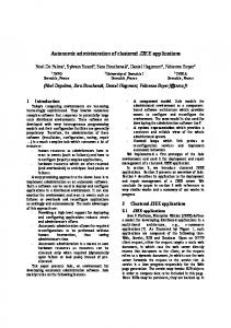
Notably, state diagrams and scenarios differ widely in breadth and scope, then the framework can be used in several ways: in [8] Charmy has been used to create a complete description of the system architecture behavior and to validate the obtained model with respect to the scenarios. In [9] the framework has been adapted to verify that a model of the system dynamics (state diagrams) corresponds to the coordination requirements (expressed by scenarios). In [7] we put ourselves in a practical industrial setting, thus assuming to deal with multiple views SA descriptions and using the tool to have a first feedback on the multiple views consistency side, checking whether the state machines and the scenarios views coherently integrate. In the same paper, we also described the tool we are developing to automatically model check these properties. To describe state diagrams and scenarios we refer to a notation general enough to encompass those generated by the architectural description languages used in the current practice and rich enough to allow for analysis. Figure 2 illustrates the notation we will use for state diagrams and scenarios. State diagrams are described using a State Transition Diagram notation close to the Promela syntax. This model is defined in [6] and used to represent Promela-based state machines. The notation is shown in Fig. 2.a where i) labels uniquely identifies the architectural communication channels and can be used only by a pair of components; ii) for each label l (e.g. ch1 and ch2 in Fig. 2.a), a ? and ! operators are defined with the following semantics: ?(!)l identifies an input (output) operation on the l channel. Note that the assumption in i) above is not restrictive since it is always possible to uniquely label a communication between two components. The parallel composition between processes is that defined by SPIN. Scenarios (Fig. 2.b) are described using a UML notation, stereotyped so that i) each rectangular box represents a component, ii) each arrow defines a communication line (a channel) between the left and the right boxes. There are several types of arrows, each one representing a particular kind of connection: the asynchronous (the half stick arrow) and the synchronous (the filled solid arrow). The arrows labels identify the communication channels and the τ denotes internal operations, i.e., something not visible from the environment. We now summarize, in an informal way, the three steps the approach is composed of: the components state diagrams are translated into a Promela specifica-
6
Paola Inverardi et al.
tion, in the first step; in the second step, the system scenarios are expressed by Linear time Temporal Logic (LTL) [20] formulae. Finally, the SPIN [20] model checker verifies the LTL formulae corresponding to scenarios on the obtained Promela [20] model. This summary on Charmy framework is enough to understand the paper. Details about the mapping in Promela and LTL may be found in [8], practical examples are described in [8, 7] and the tool supporting the approach is described in [7].
4
Specification and formalization of J2EE, EJB and AO
This section is dedicated to the specification and formalization of J2EE, EJB and Active Objects. We go through the first two levels of the process pictured in Figure 1. The first subsection concerns J2EE-EJB, the second one AOs. In both subsections, we analyze the high level specifications trying to identify architectural components. We extract static and dynamic properties of interest, formalizing behavioral aspects through scenarios. These are architectural level scenarios, showing how architectural components interact. In the second step, driven by the informal specification and by the identified properties, we refine the software architecture providing a suitable description of components and connectors architectural behavior. The last step model checks these software architecture models with respect to the formalized scenarios. 4.1
The J2EE Software Architecture and the EJB Component Model
J2EE is the Sun Microsystems solution for enterprise application development. With ”Enterprise application” we identify a special class of application which are distributed and have some special requirements, like reliability, scalability and security requirements. The J2EE architectural components are based on Java technology and provide all the middleware services needed by enterprise applications. The J2EE architectural style [18, 11] is a three-tier style and its architecture components, presented in Figure 3, are the following: – Application components: components which implement the application logic, the presentation logic and the access logic to the application services. Typical examples of this type of components are: Client, Servlets and EJB components. The grayed boxes in Figure 3 represent application components. – Container: gives the runtime support to the application components, implicitly providing the available middleware services. – J2EE Standard Services: a set of middleware services needed by enterprise applications. The most important ones are: RMI (Remote Method Invocation) which enables application components to be used in a distributed environment; JTA (Java Transaction API) used to handle application transactions; JMS (Java Messaging Service) for the reliable delivering of messages.
An Experience in Architectural Extensions: Active Objects in J2EE
7
J2EE Server WEB Container Servlet JSP Client
Database
EJB Container
EJB
Application client container Standard services
Client tier
Middle tier
Data tier
Fig. 3. The J2EE Software Architecture
– Database: which is used for data storage. Since we are interested in extending the component behavior with active objects properties, we focus our attention on the J2EE component model: Enterprise JavaBeans. EJB is an architecture for component-based distributed computing and it is the most important part of the J2EE platform. Enterprise beans are components of distributed transaction-oriented enterprise applications. They are application components and can be of two types [14]: – Session bean: components which implement the application logic. They can be further divided in two categories: • Stateful: Components which maintain a conversational state between the service invocations made by a client. Each component instance is used to serve always the same client. • Stateless: Components which do not maintain a conversational state between the service invocations made by a client. A generic component instance may be used to serve different clients. – Entity bean: Components which give an object-oriented representation of the data stored on a persistent storage (database). All the component types are deployed in a container which acts as a wrapper in order to: 1. provide the support needed by the components to be used in a distributed environment. RMI is used for this purpose;
8
Paola Inverardi et al.
2. manage the components life-cycle (instance creation and destruction); 3. filter clients requests in order to optimize system resources and components instance usage; 4. manage data transaction in a distributed and concurrent environment in order to guarantee data integrity. The life cycle management is achieved using a Home Object while the other operations are handled by Remote Objects. Each EJB instance (the BeanClass) is managed by the container and is deployed in a concurrent environment: the computation done by an instance is carried on in parallel with the computation of other instances. However, a single EJB instance is non-reentrant, that is, a client cannot perform concurrent calls to a single component instance2 . At last it’s useful for our purposes to point out that RMI allows only synchronous invocations: a client which requests a service must wait the computation to end before continuing. It means that an EJB can be accessed only in a synchronous way. Starting from this informal specification, the EJB static architecture can be identified as shown in Figure 5. Next step is to identify relevant dynamic properties and formalize them by means of architectural level scenarios. EJB Properties formalization EJB1 All instances of an EJB component is non-reentrant: a client is not able to concurrently call the same instance of a component.
Client
Client
EJB Client
EJB
invoke invoke invoke exception avail
avail
return return a)
b)
Fig. 4. EJB1 and EJB2 Scenarios
We formalize this property with the scenario in Figure 4.a. It shows that an exception is raised, in case of concurrent calls to a stateful component. 2
This is true only for stateful session beans. Since an instance of a stateless session bean could serve any client, the container is able to redirect concurrent calls to different instances.
An Experience in Architectural Extensions: Active Objects in J2EE
9
EJB2 The invocation of an EJB component service is executed using RMI and it is, therefore, synchronous: a client that invokes a service is blocked waiting for the end of the required service computation. In this case we use a refutational approach. The scenario, in Figure 4.b, formalizes that the client and the EJB component can compute concurrently, then we prove that this scenario is never verified. EJB Software Architecture In this section we refine the description and provide a more detailed software architecture for EJB. An EJB component is made of the following parts:
EJB Container
EJB EJB
Bean Class RO
HO EJB RMI
Client Fig. 5. EJB1.1 Software Architecture
– Enterprise Bean Class: It is the object which contains the actual implementation of the application logic. – EJB Remote Object (RO): it is the layer between the client and the actual component. It intercepts all the calls to the component and enables the container to do set-up operations (as previously described in 4.1) before forwarding the call to the actual component instance. – Home Object (HO): it is the object which enables the client to acquire references to EJB Objects. Both the EJB Remote Object and the Home Object are automatically generated by the container, depending on the component properties3 and services. The EJB static architecture is shown in Figure 5 while the components behavior is shown in Figure 6: the Client component has either internal operations (“τ ”) or makes requests to the RO component. RO invokes the EJB BeanClass and waits for the results. The EJB BeanClass computes the results and sends them back to RO. Finally, the Client receives the results (“?avail”). 3
For example what type of transaction support is needed.
10
Paola Inverardi et al.
We can now prove that the EJB software architecture model conforms to the properties EJB1 and EJB2. This is enough for us to assess the conformance of this software architecture with respect to the high level specification.
?invokeBC
?notavail !checkres
?invoke
!returnBC
?avail ?return !invoke
!exception
?invoke
!invokeBC
!availBC
?exception
?availBC
!return
n ur et
?a va il
?r a) Client
?invoke !exception
?returnBC
!avail
b) BeanClass
c) Remote Object
Fig. 6. EJB1.1 Components behavior
4.2
Active and Passive Object
There are many different definitions of Active Objects [10, 13]. The typical definition says that “an active object is an object or a component with its own thread of control”. This definition is too abstract and vague for our purposes. Thus we refined it in order to identify a well defined class of objects characterized by the abstract property of having a thread of control. Our analysis resulted in the following informal description of AO. It is the starting point to identify and formalize the high-level specification corresponding to the first level in Figure 1. 1. an AO must be able to concurrently run with respect to other entities running in the system and, above all, with the client which requested its services; 2. an AO has a well defined interface that is exposed to other components and shows functionalities or services implementing the AO behavior; 3. An AO may have a per-client state that is held during the computations. Following this property, it is possible to define Stateful AO (those that held their internal state during all the life cycle related to a certain client) or Stateless AO (those objects that do not have a global internal state). From these properties we can argue that in order to be an AO, a component must support the asynchronous method invocation. The above definitions have been identified in the EJB context. This means that they might need to be revisited in other contexts. Moreover, since Active Objects are a special class of components, we should consider that: – exported methods may get parameters as input values;
An Experience in Architectural Extensions: Active Objects in J2EE
11
– exported methods may return some results. The second aspect is especially relevant since it introduces the issue of results handling. Typically a client asynchronously invokes a method, receives back the control and then runs in parallel with the called object. When the results have been computed by the called object, the client must be able to retrieve these values. This means that an AO model must provide a way to manage this situation. Summarizing, the relevant properties an object must exhibit to be an AO are the following: – parallel method execution with the client which requested it; – support to results retrieval. These two properties represent AO dynamics aspects that will be formalized in the following section. At this level of description an AO is just a component as described in Subsection 4.2.
AO Properties formalization AO1 An AO must be able to concurrently run with the client which requested its services. This property is needed to achieve the asynchronous method invocation. Active Object
Client invoke τ
τ
Fig. 7. Scenario AO1
The scenario pictured Figure 7 shows the parallel computation between a Client and an Active Object. AO2 An AO must provide a mechanism to retrieve results. Since the computation is carried on independently of the client, there must be a way to check that the computation has finished and to retrieve the results. The scenario in Figure 8 shows the interaction between a Client and an Active Object. Notice the results requests (“checkres”) and the availability of the results only when the computation is actually over.
12
Paola Inverardi et al. Active Object
Client
Active Object
Client
invoke
invoke
return
return
checkres
checkres
notavail
avail
Fig. 8. Scenario AO2
AO and PO Software Architecture The AO component that behaves as formalized in Figure 9.a): the client “invoke” the AO, the AO “return” the control to the client. The client may now send other invoke requests or ask to the AO results for previous computations. They will be available (“avail”) only when the computation is finished (“τ ”). Differently from AO, Passive Objects are components that do not allow asynchronous invocation. Figure 9.b) describes the PO behavior. Analogously to what we have done for EJB, we can now prove that the AO software architecture model correctly behaves with respect to properties AO1 and AO2. On the other hand, as expected, PO SA model does not.
!return
S2
S4
!avail
?invoke
?invoke
S6
?invoke
S1
!return
S1
?checkres
?invoke
S0
!return
!notavail
S0
!notavail
?checkres
S3
S3
!avail
S2
S5 a)
b)
Fig. 9. a)Active Object model, b) Passive Object model
5
EXTENDING J2EE WITH ACTIVE OBJECTS
In this section we propose solutions to the extension problem. We proceed in an incremental way. We first carry on a preliminary analysis which outlines the need of a serializer architecture and then we describe how this architecture can be suitably integrated in EJB in order to provide a correct SA model for Active Objects.
An Experience in Architectural Extensions: Active Objects in J2EE
5.1
13
Active Object on J2EE Architecture
A preliminary idea to avoid the RMI restriction regarding synchronous invocation is to encapsulate each invocation in a separate thread which will carry it on independently. In this way, the independent thread will wait the invocation to complete while, the other components are free to continue their job. These supplementary threads could be instantiated either on the component side or on the client side. In both cases the specification is violated [14]: component side threads are explicitly not allowed since they will interfere with container operations (such as resource coordination policies, resource allocation and correct transactions management). Client side threads, on the other hand, potentially permitted, could lead to concurrent calls to the same component instance, thus violating a previously cited property (Section 4.1). This first analysis suggests to refine this first approach concentrating on the client side and trying to avoid the concurrent call to the same component instance problem. This can be done by creating a serializer which filters all the invocations and executes them one by one. This intuition will lead us to the solution we propose for the architectural extension. The development of this intuition, will lead us to the solution proposed for the architectural extension. The serializer will be composed of the following components: 1. The Buffer which stores the invocation requests not yet executed. 2. The Scheduler, which gets the requests and carries on the actual invocations. The scheduler will run in parallel with the other system components. 3. The passive object, which contains the application logic. This serializer architecture is enough to achieve the AO concurrency property (AO1), as described in Section 4.2, but is not enough to satisfy all of them. Since there is not a direct link between Client and components, there is not a “well defined interface” to the services and, more importantly, there is not a clear mechanism to “recover the computation results” (i.e., property AO2 in Section 4.2 is violated). Thus we introduce two other components: 4. the Future which will contain the results of a particular method invocation. This component will be directly connected both with both the client requesting the service and the scheduler that runs the invocation. It will be used by the Client to check if the requested computation is terminated, and eventually, to get the results; 5. the Proxy component is introduced to contain the encoding mechanisms for the requests. This component guarantees the client transparency with respect to synchronous and asynchronous calls, providing an interface to the functionality implemented by the Passive Object. The Future and the Proxy components fuctionalities could have been encoded into the Client but this solution will limit the Client transparency.
14
Paola Inverardi et al. AO
Serializer
Proxy Queue
Future
Scheduler
PO
Fig. 10. The AO architecture
The final architecture is shown in Figure 10. Components behavior is in Figure 11. The “Proxy” receives an invocation, enqueues the message (encoding the invocation), and immediately returns the control. The “Scheduler” takes the request from the “Queue” and invokes the actual implementation on the “PO”. When the “PO” computation finishes, it sends back the results to the “Scheduler” that stores them into the “Future”. This component can be queried for results availability. This model has been checked proving its conformance to the identified highlevel properties. It makes us confident that this architecture is a valid implementation of the AO higher-level architecture defined in 4.2. In the next subsections we will show how this AO software architecture can be integrated with the EJB architecture in order to provide active objects in EJB.
?invoke
!get
!invokeEJB
!enqueue
!return
!setres
?availEJB ?returnEJB
a) Proxy c) Scheduler
?enqueue
?enqueue
?get
?get
!notavail !avail ?checkres !notavail ?checkres
?setres d) Future
b) Queue
?setres
Fig. 11. The AO components behavior
An Experience in Architectural Extensions: Active Objects in J2EE
5.2
15
Extending EJB1.1 with the AO architecture
We start from the AO architecture (Figure 10). In this architecture there is a passive object component. Since EJB1.1 components expose the same properties of a passive object [14], we replace the PO component in the AO architecture, with the EJB1.1 component. Figure 12 shows the integrated architecture topology, that will be denoted as EJB1.1+AO. From the dynamic point of view, its components behave similarly to components in the EJB1.1 (Figure 6) and AO (Figure 11) architectures. The new model only differs because, the Client sends the invocation to the Proxy (instead of the Remote Object) and the EJB component is directly used by the Scheduler, instead of the Client. Moreover, new behaviors may appear: the Scheduler in this new architecture has to manage also additional behaviors due to the EJB integration.
AO EJB
Scheduler
Queue
Future
Proxy
Extension Client
Fig. 12. EJB1.1 + AO Architecture
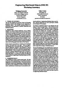
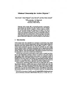
In Figure 13 there is an excerpt of these proofs: the Remote Object component state diagram (a) is edited by the StateDiagram editor tool, it is automatically translated into Promela (b) following the algorithm defined in [8], scenario AO1 (c) is edited through the ScenariosEditor and automatically translated into the corresponding LTL formula (d). Running SPIN, the four scenarios formalized in Section 4 have been proved to be correctly implemented by our EJB1.1+AO model. For implementation reasons, we preferred to check the negation of some scenarios. In particular, we asked to SPIN to check if scenario AO1 (also in Figure 13.c) is never verified. The output, shown in Figure 5.2, is “claim violated” that means that scenario AO1 is possible. In the next section, we reconsider the extension problem in the EJB2.0 context.
16
Paola Inverardi et al.
Fig. 13. Using Charmy: an example
pan: claim violated! (at depth 99) pan: wrote pan_in.trail(SpinVersion 3.4.7 -- 23 April 2001) State-vector 1540 byte, depth reached 99, errors: 1 682 states, stored (683 visited) 8659 states, matched 9342 transitions (= visited+matched) 9757 atomic steps hash conflicts: 0 (resolved) (max size 2^23 states) 34.771 real
memory usage (Mbyte) 1.9 user
1.6 sys
0.2
Fig. 14. SPIN result for AO1
An Experience in Architectural Extensions: Active Objects in J2EE
6
17
Extending EJB 2.0 with the AO architecture
The current EJB specification (EJB2.0) [3] has introduced many new features, including a way to perform asynchronous method invocation. To accomplish this task a new component type has been added: the Message Driven Bean (MDB). MDBs act as message queue listeners implemented through the Java Messaging Service (JMS). MDBs do not have neither a Remote Object nor a Home Object. The only way for a client to interact with a MDB is to send a message to the JMS (Figure 15). MDBs behaves like Stateless Session Beans. The integration between the container and the JMS enables the notification to the MDB of the arrival of a message on the queue the MDB is listening on. A special method ”onMessage” is called and the message sent by the client, is passed as a parameter. This solution enables the asynchronous invocation of a service implemented using an MDB. Once a client has sent a message, it can continue its activity independently from the notification process and from the execution of the service implemented with the ”onMessage” method.
EJB Container
MDB MDB MDB
EJB EJB
Bean Class RO
J M S
HO EJB RMI
Client Fig. 15. EJB2.0 Architecture
Intuitively, we could argue that MDBs may provide a feasible solution to the asynchronous method invocation problem. However, MDB components present some limitations which violates the Active Object properties: – statelessness: the components behaves like a stateless session bean; – lack of trasparency: the client must call the MDBs components differently by the other components. There is not a clear interface to the component. It means that asynchronous invocation differs, from the client point of view, from synchronous one; – communication problems: there is not a clear way to handle parameter passing and results recovery. Due to the enhanced EJB2.0 features, we will try to directly map the AO architecture components to the EJB2.0 architecture components:
18
Paola Inverardi et al.
– the JMS behaves as a Queue; – the Scheduler functionalities are shared between the container-JMS integration (message retrieval) and the MDB component (actual service invocation); – the Passive Object will be a stateful (or possibly a stateless) EJB; – the Proxy is implemented by stateless EJB components which will expose the same interface of the Passive Object. It takes care of encoding the invocation to a message which is delivered to the JMS; – the Future is replaced by entity bean components which will store the results for a later retrieval. The EJB2.0+AO architecture is shown in Figure 16
EJB Container
EJB EJB Future (Entity Bean)
(Service Logic)
MDB
EJB Proxy
JMS Scheduler
Client Fig. 16. EJB2.0+AO Architecture
This extended architecture meets the Active Object properties but, checking its correctness with respect to the EJB properties, SPIN found an error trail: when a client makes two different asynchronous invocations (to the same component) and the second one is run before the ending of the first one, an exception is raised. The SPIN error trail puts in evidence that this unexpected behavior is due to Container which runs MDBs in parallel leading to the concurrent component invocations violating the property EJB1 in Section 4.1 (Figure 4.a). This result suggests that even in the enhanced EJB2.0 context the first solution we proposed still remains preferable.
7
Conclusions
We have presented the result of an experiment on architectural extension. The achieved results are two. The description of an extension which is a correct realization of its specification and the definition of an approach, and of a supporting
An Experience in Architectural Extensions: Active Objects in J2EE
19
framework, to carry out architectural extensions in a correct way. The approach rigorously defines what we mean for architectural specifications, at different levels of abstractions, and what we mean for correct realization. Moreover it shows that it can be supported by tools. We have experimented our ideas in the context of the Charmy environment but the approach we propose is obviously independent from the specification formalisms used and from the checking techniques. Future work will go in two directions. We are trying to experiment with different kind of high level properties or requirements; typically we would like to address non functional requirements like security. From the framework side we want to make the whole framework more integrable with standard development environments, notably UML based.
Acknowledgments The authors would like to acknowledge the Italian M.U.R.S.T. national project SAHARA that partly supported this work.
References 1. R. Allen and D. Garlan. A Formal Basis for Architectural Connection. ACM Trans. on Software Engineering and Methodology, 6(3):213–249, July 1997. 2. L. Bass, P. Clements, and R. Kazman. Software Architecture in Practice. AddisonWesley, SEI Series in Software Engineering, 1998. 3. L. G. DeMichiel, L. mit Yalinalp, and S. Krishna. Enterprise JavaBeansTM Specification, Version 2.0. On-line at , year2001. 4. A. Filkenstein, D. Gabbay, A. Hunter, J. Kramer, and B. Nuseibeh. Inconsistency Handling in Multi-Perspective Specifications. IEEE Trans. on Software Engineering, 20(8):569–578, 1994. 5. P. Fradet, D. L. Metayer, and M. Perin. Consistency Checking for Multiple View Software Architectures. Proc. European Software Engineering Conference (ESEC/FSE’99), pages 410–428, 1999. 6. G. J. Holzmann. Design and Validation of Computer Protocols. Prentice Hall, 1991. 7. P. Inverardi, H. Muccini, and P. Pelliccione. Automated Check of Architectural Models Consistency using SPIN. In the Automated Software Engineering Conference Proceedings (ASE 2001). San Diego, California, November 2001. 8. P. Inverardi, H. Muccini, and P. Pelliccione. Checking Consistency Between Architectural Models Using SPIN. In TR 02/01, University of L’Aquila. On-line at , year 2001. 9. P. Inverardi, H. Muccini, and P. Pelliccione. Checking Consistency Between Architectural Models Using SPIN. In Proc. the First Int. Workshop From Software Requirements to Architectures (STRAW’01), year 2001. 10. T. Jenkinson. The Active Object Design Paradigm. Online at .
20
Paola Inverardi et al.
11. N. Kassem and the Enterprise Team. Designing Enterprise Applications with the JavaTM 2 Platform, Enterprise Edition. On-line at , year 2000. 12. R. Kazman, L. Bass, G. Abowd, and M. Web. Saam: A method for analyzing the properties of software architectures. Proceedings of ICSE 16, Sorrento, Italy:81–90, May 1994. 13. R. G. Lavender and D. C. Schmidt. Active Object - An Object Behavioral Pattern for Concurrent Programming. Proceeding fo the Second Pattern Languages of Programming conference, Monticello, Illinois, 1995. 14. V. Matena and M. Hapner. Enterprise JavaBeansTM Specification, v 1.1. On-line at , year1999. 15. M. Moriconi, X. Qian, and R. A. Riemenschneider. Correct Architecture Refinement. IEEE Trans. on Software Engineering, 21(4), April 1995. 16. S. Nakajima and T. Tamai. Behavioural Analysis of the Enterprise JavaBeans Component Architecture. Proceedings of the 8th SPIN Workshop, LNCS 2057, 2001. 17. J. Ryser and M. Glinz. A Practical Approach to Validating and Testing Software Systems Using Scenarios. QWE’99: Third International Software Quality Week Europe, Brussels, Nov 1999. 18. B. Shannon. Java 2 Platform Enterprise Edition Specification, v1.3. On-line at , year 2001. 19. J. P. Sousa and D. Garlan. Formal Modeling of the Enterprise Javabeans Component Integration Framework. World Congress on Formal Methods in the Development of Computing Systems, LNCS 1709, 1999. 20. SPIN. Home page on line at: . 21. S. Stoller and W. Visser. Proc. Workshop on Software Model Checking. ENTCS, 55(3), 2001. 22. S. Uchitel, J. Kramer, and J. Magee. Detecting implied scenarios in message sequence chart specifications. Proc. European Software Engineering Conference (ESEC/FSE’01), 2001. 23. A. van der Hoek, M. Mikic-Rakic, R. Roshandel, and N. Medvidovic. Taming architectural evolution. Proc. European Software Engineering Conference (ESEC/FSE’01), 2001.