Active Pixel Sensor Arrays in 90/65nm CMOS-Technologies with vertically stacked photodiodes S.Henker1, C. Mayr1, J.-U. Schlüßler1, R. Schüffny1, A. Heittmann2, U. Ramacher3 1
Univ. of Technology Dresden, Institute of Circuits and Systems (IEE), Helmholtzstr. 10, 01062 Dresden, Germany, {henker,mayr,schlue,schueffn}@iee.et.tu-dresden.de, Tel.: ++49 351 463 33602, Fax: ++49 351 463 37794 2 Qimonda AG, Munich, Germany,
[email protected], Tel.: ++49 89 234 52067 3 Infineon AG, Munich, Germany,
[email protected], Tel.: ++49 89 234 41296
Image sensors using 90nm and 65nm CMOS technology were developed, exhibiting characteristics competitive with commercial sensors in conventional technologies. New pixel configurations with stacked photodiodes and high fill factor have been evaluated. Image sensors in deep-submicron can take full advantage of the technology shrink for digital image restoration, balancing remaining technological deficiencies and offering additional processing capabilities. Today’s CMOS sensors are chiefly fabricated in 0.25µm CMOS technology and incorporate a custom DSP for image enhancements [1]. This work is focusing on evaluation of 90/65nm CMOS technology for active photosensor arrays and analog/mixed signal readout circuits. To compensate for the expected larger insufficiencies of the analog sensor array, advantage can be taken of the shrinking potential of further sub100nm CMOS technologies to implement image enhancement techniques by digital post processing [2, 3]. Application is aimed at embedded imagers for digital cameras in handhelds and alike, using standard digital processes for Systems on Chip. As far as the authors are aware, this is the first study of pixel sensors in sub-100nm CMOS technologies. Two active pixel arrays have been fabricated in 90nm and 65nm CMOS process respectively with 6+1 layer metal stack and copper interconnects (Figure 6). The first chip serves for pixel evaluation and contains a total of 21 pixel arrays with different photo diode and reset configurations. Pixel size is 6x6µm and fill factor is varying between 44 and 60%. The second chip has been designed in 65nm CMOS technology to evaluate a larger sensor array and analog and mixed-signal components of the readout data path. It contains a 128x96 pixel array of 6x6µm dual channel pixels with 46% fill factor (Figure 1). Additional a 48x96 pixel array of smaller 3x3µm single channel pixels utilizing embedded transistor reset and 38% fill factor (Figure 2) is inserted. Beside the pixel arrays, the 65nm evaluation chip also includes circuits for analog processing such as several amplifiers, a pipeline ADC and a Σ∆-ADC and their associated digital controls. For sensor operation we use linear light energy measurement by integrating a reverse biased junction diode capacitor. The measurement process consists of 3 phases: the resetting of the capacitor to a fixed voltage using a reset element, the integration of the light induced current over a distinct amount of time and the readout of the voltage difference on the capacitor using a readout element. The received light energy is then directly proportional to the voltage change on the capacitor. Reset and readout on pixel level are commonly implemented with a transistor switch respectively a source follower, resulting in a 3T pixel cell [4]. The general problems with imager design on sub-100nm derive mainly from technology constraints [5]: The consequences of transistor scaling are increased leakage due to high doping concentration, steep implant profiles and increased oxide interface trap states caused by shallow trench isolation. Short channel effects significantly increase transistor off-current and some devices also show considerable gate leakage which further discharge integrating and sample&hold capacitors [5]. For purpose of comparison, we use different transistor options on the 90nm chip, such as low leakage devices (LLD) and analog IO devices (ANA) and implemented different reset circuits and different reset schemes to reduce leakage and suppress temporal noise (Figure 6). Compared with LLD, analog IO devices show several advantages, esp. lower channel leakage and basically no gate leakage. LDD transistors are smaller in size, but operate at
16
1.2V supply voltage, which reduces the available signal swing and dynamic range. Since leakage is generally increasing with technology shrink, the sensor in 65nm technology is implemented using IO devices only. Further, we are using different configurations of junction diodes as photo element, focusing on well diodes, since the junction leakage of diffusion diodes is in general orders of magnitude higher because of their doping concentration. In general, well diodes are not very common in pixel design due to their large interspace requirements. Our solution is to partially compensate this by applying moat layers, which prevent the doping implantation of the surrounding p-well. The resulting p-i-n diode structure shows reduced junction leakage and an enhanced depletion region as well as smaller capacitance and thus improved sensitivity. However, due to the implantation depth, a well diode shows higher sensitivity especially in the infrared region compared to shallow diffusion diodes.
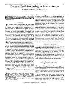
Figure 1: 6T dual channel pixel In addition, different pn-junctions (n-well, diffusion, triple-well) were arranged to form vertically stacked photo diodes with distinguishable spectral characteristics [2] (Figure 1). These pixel structures require separate reset and readout for the different diodes, but provide multiple output signals. These outputs are sampled on identical spatial and temporal coordinates. These multi-channel sensors avoid/simplify the color filter array necessary for color reproduction in visual range. Furthermore multi sensor channels allow in particular to control the infrared response by using a novel approach to suppress or emphasize infrared light for special applications [3].
Figure 2: 3T pixel cell with embedded PMOS reset Using single channel pixels, the fill factor of a well diode pixel can be further improved by embedding a PMOS reset transistor directly into the diode n-well (Figure 2). Compared to standard NMOS reset this special technique gives the advantage of threshold voltage dependent fixed pattern noise cancellation and an increased signal swing at the expense of higher transistor leakage. Measurement results prove that important imager parameters like sensitivity, dark current, and resolution
17
in a standard deep-submicron CMOS technology are comparable with state of the art CMOS-imagers using special photo process options (Figure 3). The FEOL part of photosensitive elements, i.e. the dopant profiles, is usable for visible range and infrared. Feature
Unit
pixel size
µm2
integrating capacitor dark current sensitivity
C / fF
8.2
13.2
12
16.2
11
4.3
4.5
Rdark/ mV/s
23
37
210
71
50
7700
6.29
saturation
Nsat / e-
61199
98876
89888
120974
82397
48315
22472
reset noise (kT/C) 1) dark current noise noise floor
Nrn / e-
36
46
44
51
42
26
20
Ndn / e-
23
61
315
143
69
2067
4
Nn / e-
43
76
320
152
81
2067
21
SNR 2)
dB
61.2
59.3
48.0
55.9
60.2
27.4
61
1) 2)
90nm, 90nm, nwell nwell/pdiff with moat with moat 6x6 6x6
90nm, 90nm, 65nm, nwell nwell/pdiff nwell w/o moat w/o moat with moat 6x6 6x6 6x6
65nm, 180nm nwell Reference w/o moat [5] 3x3 3.5x3.5
reset noise is assumed to be 1*sqrt(kT/C), not yet measured, (Reference [5]: 0.75*sqrt(kT/C)) based on measurements of dark current and reset-noise estimation
Figure 3: Comparison of different diode configurations Figure 4 (left side) shows the spectral sensitivity of different diode configurations of the 90nm design. Within the right side of this figure sensitivities of the double channel pixel and the smaller single channel pixel on 65nm chip are compared. As seen in Figures 4, sections of spectral range are suppressed. This is caused by the copper wire metal stack with many dielectric layers and strong varying reflective index, which leads to distinct interference effects, since the layer thickness is within the range of λ/2. The main minima of the resulting light transmission characteristic are determined by layer structure, thickness and dielectric coefficient of the isolating materials of the backend process, but the transmission characteristic also shows high variability due to the strong dependence on fabrication parameters.
Figure 4: Spectral sensitivity of 90nm (left) and 65nm (right) photo diodes (30nm spectral gap width) Simulated transmission characteristics show a good match with measured characteristics and can thus be used for technology optimization in respect to photo sensors [5]. Figure 5 shows sample images taken from contiguous pixel areas of the test chips.
18
Figure 5: Images samples taken with pixel evaluation chip (top) and sensor evaluation chip (bottom)
Figure 6: Die Photographs
References
[1] U. Ramacher, I. Koren, H. Geib, C. Heer, T. Kodytek, J. Werner, J. Dohndorf, J.-U. Schlüßler, J. Poidevin, S. Kirmser, “Single-Chip Video Camera with Multiple Integrated Functions,” International Solid-State Circuits Conference ISSCC'99, pages 306-307, 1999. [2] A. E. Gamal, “Trends in CMOS image sensor technology and design,” Digest of IEEE International Electron Devices Meeting, pp. 805-808, December 2002. [3] S. Henker, J.-U. Schlüßler, R. Schüffny, “Concept of Color Correction on Multi-Channel CMOS Sensors,” Digital Image Computing: Techniques and Applications, Proc. of the 7th Biennial Australian Pattern Recognition Society Conference - DICTA 2003, vol. 2, pp. 771-780, Dec. 2003. [4] J. Yang, K. G. Fife, L. Brooks, C. G. Sodini, A. Betts, P. Mudunuru, H.-S. Lee, “A 3MPixel Low-Noise Flexible Architecture CMOS Image Sensor,” ISSCC Digest of Technical Papers, pp. 496-497, Feb. 2006. [5] IBIS4-6600 High resolution 6.6 M Pixel Rolling shutter CMOS Image sensor Datasheet, Cypress Semiconductor Corporation, San Jose, CA, 2005.
19