The 10th of International Symposium on Transport Phenomena and Dynamics of Rotating Machinery Honolulu, Hawaii, March 07-11, 2004
Paper ID Number 073
ACTIVE STABILITY CONTROL OF THE COMPRESSION SYSTEM IN A TWIN-SPOOL TURBOFAN ENGINE BY AIR INJECTION Stephan G. Scheidler, Christian Mundt Institut für Strahlantriebe, Institut für Thermodynamik Universität der Bundeswehr München Werner-Heisenberg-Weg 39 D - 85577 Neubiberg Germany Tel.: ++49 - 89 - 6004 - 2055 Fax: ++49 - 89 - 6004 - 4541 e-mail:
[email protected]
Manuel Mettenleiter, Jakob Hermann IfTA GmbH Industriestr. 33 D - 82194 Gröbenzell Tel.: ++49 - 8142 - 65051 - 79 Fax: ++49 - 8142 - 65051 - 61 e-mail:
[email protected]
Sven-Jürgen Hiller MTU Aero Engines GmbH Dachauer Straße 665 D - 80995 München Tel.: ++49 - 89 - 1489 - 8716 Fax: ++49 - 89 - 1489 - 6330 e-mail:
[email protected]
ABSTRACT This investigation presents an active stability control system on a twin-spool turbofan engine to recover from unstable operating conditions or to avoid them. Therefor air injection in the tip region ahead of the first low pressure compressor (LPC) rotor is used to damp any instabilities and their precursors. A high frequency instrumentation is applied to detect the flow disturbances and to feed the control system with the measured values. An injection casing, consisting of 10 injection ducts and pivoted nozzles at their ends is equipped with fast acting direct drive valves to provide the required air flow. This air is delivered by an external source. In this paper it is focused on the phenomena in the low and medium speed range of the LPC where fully developed rotating stall appears prior to surge. In the control section it is shown that the stabilizing effect of an additionally injected constant air flow can be further increased by using active control methods, leading to a dynamically modulated injection. In this case less air is required to obtain a comparable improvement or for the same amount of air the stable operating range can be further enlarged. A numerical model was built which is able to reproduce the experimentally gained results in good manner.
NOMENCLATURE Symbols Fs [kN] thrust f, frot [Hz] frequency, rotor frequency n [RPM] mechanical spool speed ps, pt [Pa] static pressure, total pressure Π, PI [-] pressure ratio relative corrected spool speed, nθLPC [%] (nLPC/√Tt,LPC,inlet)rel. W [kg/s] mass flow WRED[kg/s•√K/bar] corrected mass flow Abbreviations AIC BPR DDV DSP FFT ISA HP, HPC LP, LPC PSD RMS TET
1
active instability control bypass ratio direct drive valve digital signal processor Fast Fourier Transformation international standard atmosphere high pressure, high pressure compressor low pressure, low pressure compressor power spectral density root mean square turbine entry temperature
INTRODUCTION An important aspect in the use of rotating machinery is the efficiency in operation and the improvement of it. Usually the highest efficiency rates can be utilized close to the surge line. This leads to the intention to reduce the surge margin of compressors to gain some valuable operating range. Thus the aerodynamic stability of a gas turbine or a flight engine is a mandatory task in the design process of modern turbomachinery. Thereby it is the aim to either increase the stage loading while keeping the number of rotors and stators constant or to maintain the aerodynamic load together with a reduction of the stage count. Both provisions lead to highly loaded blades which are jeopardized by unstable operation. Rotating stall, surge and other forms of instabilities and their precursors are results of this. To cover these flow phenomena and to allow to operate an engine also at critical flow conditions, closer to its instability barrier, an active stability control system needs to be employed. While in the past mainly passive measures like casing treatment and variable inlet guide vanes have been applied to artificially stabilize the flow in the entire compression system, in this study a real active method is investigated. For this purpose air delivered by an external source is injected in the inlet area ahead of the first low pressure compressor (LPC) rotor. Since the investigated system, a twin-spool turbofan engine, earliest gets unstable in the first LPC rotor blade tip gap this active stabilization method allows to avoid instabilities or to delay them, depending on the way and amount of air injection and depending on the operation mode of the engine. To apply such a stability control system it is mandatory that it assures the aerodynamic stable operation of the compressor at all operating conditions (also transient manoeuvres), at all inlet conditions and at all engine deterioration conditions. This requires an early, exact and reliable detection of stall precursors and a control system with an appropriate actuation. Extending the operating range of a compressor by air injection into its front stage or unloading the blades using fast acting bleed valves are effective methods of actuation. A so-called closed loop system which moves the actuators based on the signals measured of relevant flow parameters is an active control system. Such a system is presented in this publication starting from the results of similar active control devices designed and applied for high speed compressor rigs (Spakovszky et al., 1999 and Weigl et al., 1998), a small gas turbine (Nelson et al., 2000) and a single-spool turbojet engine (Freeman et al., 1998). The stabilizing effect of air injection can be achieved in two different ways. The investigation started with constant air injection. In this application a constant amount of air is injected ahead of the first LPC rotor via 10 injection ducts embedded in a special casing located in front of the LPC. At the end of each of these 10 injection ducts pivoted nozzles are situated to vary the injection angle of the
inserted air flow. The injection angle can be modified from -30° to +30°. Air injection in positive direction corresponds to an intervention in the same direction the LPC spool rotates. The valves through which the air is distributed to the injection ducts are fast acting direct drive valves (DDVs) by Moog company, Germany. These allow also to modulate the inserted air flow, thereby modulated air injection can be applied as well. Once an online-monitored stability parameter derived from high sample rate pressure signals exceeds a defined threshold the constant or modulated air injection is started. With this kind of engagement spikes can be eliminated and Rotating stall can be postponed to lower values of corrected mass flow. The more sophisticated way is the air injection guided by the controller. In this application five high sample rate pressure signals are used as an input signal for the controller. These signals have been delivered by miniature pressure sensors located in equal circumferential distance positioned ahead of the LPC. Due to the fact that high speed compressors do not always stall via modal waves and that the instability inception process differs with speed and inlet conditions, as Day et al. (1999) have proven, the employment of this controller gives an additional improvement within the described active stabilization. The applied controller is a derivative of a commercial control system (AIC-system) which has been presented by Hermann et al. (1999) to actively control thermoacoustic instabilities in combustion chambers of stationary gas turbines. The analysis presented here focuses on the air injection regulated by the control system. It is investigated with the twin-spool turbofan engine LARZAC 04. Since its first LPC rotor is tip-critical it is a suitable test vehicle for the described kind of active stability control by air injection ahead of this first LPC rotor. Additionally, it exhibits different kinds of instabilities and stall inceptions at different rotor speeds. Former investigations on this test vehicle by Höss et al. (2000) demonstrated spike-initiated instability phenomena at low speed regions. The quoted weak indications for a stall inception via modal waves by Leinhos et al. (2002) in the mid speed regime are not supported since the compression system in this region also showed spikes as accountable stall precursors. It is confirmed that in the upper speed range a perturbation rotating at LPC rotor frequency (shaft order) is responsible for instability onset there. The objective of the work is to demonstrate the capabilities of such an active stall control taking into consideration the specific conditions and the practical imperfections of an operational twin-spool turbofan engine as a real application for a propulsion system of an aircraft. The intention is to learn more about the limitations connected with it and the possible benefits. All results presented focus on the lower part of the speed region in which spike-induced rotating stall is the dominant instability phenomenon.
2
EXPERIMENTAL SETUP Test Engine The tests were carried out at the institute’s ground test facility using the low-bypass twin-spool turbofan engine LARZAC 04 C5. The engine is of modular twin-spool design and is not equipped with inlet guide vanes in front of the LPC. Due to this reason it is well suited for the herein described investigation with air injection ahead of the first LPC rotor, since the injected air flow can directly influence the critical flow in the tip region of the first LPC rotor blades. The LARZAC 04 C5 engine consists of a highly transonic two-stage low pressure compressor (LPC), a four-stage high pressure compressor (HPC), an annular combustion chamber and single-stage high and low pressure turbines (see Fig. 1).
Bypass throttle
Core throttle
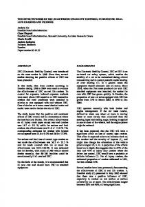
Fig. 2: Bypass and Core throttle devices
Table 1: LARZAC 04 C5 performance data
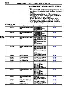
Air Injection System The aluminium injection casing was 3D-CAD-designed and is mounted in front of the LPC casing, integrated in the engines inlet duct. It comprises 10 injection channels which lead the air to the nozzles. The air is delivered by fast acting direct drive valves (DDVs) positioned at the injection channels inlet holes. The nozzles are responsible to accelerate the flow when passing and to provide a highly st subsonic air stream to the 1 LPC rotor. Since they are pivoted it is possible to vary the direction of the injected air stream up to +/- 30° in circumferential direction (see Fig. 3). A positive injection angle corresponds to an injection in rotational direction of the LPC spool. The variation of the injection angle occurs simultaneously by a collective movement of the nozzles with an actuator ring they are fixed to. The distance between the injection nozzles and the rotor blades corresponds to about two mean chord lengths to keep a mechanical feasible minimum space. Also the position of some engine accessories does not allow a closer positioning of the nozzles with respect to the blades. However this allows the injected air stream to expand somewhat to cover a wider range of the tip region. The system is designed to supply a mass flow of up to 5% of the nominal overall engine mass flow.
The core and bypass stream expand through separate nozzles without being mixed. This allows a nearly independent throttling of both compressors. In order to operate the LPC of the test engine above its steady state running line a special bypass nozzle device is used. By closing the circular arc segments of this bypass nozzle device (see Fig. 2) in radial direction the bypass nozzle area can be continuously reduced and the LPC can be throttled independently from the HPC in the first instance. To throttle the core part of the engine and to influence the HPC a rotational body can be moved in axial direction. This core throttle was not used in the presented study.
Fig. 3: Air injection system, pivoted nozzles
Fig. 1: Model of the LARZAC 04 C5 twin-spool engine The main engine’s performance data at ISA conditions are presented in Table 1.
Fs TET µ (BPR) W (mass flow) ΠLPC ΠHPC nLPC nHPC
13 kN 1403 K 1.13 27.64 kg/s 2.26 4.60 17500 RPM 22561 RPM
3
The air is provided by an external source. This compressed air system is composed of a screw compressor, a compressed air dryer, storage vessels, a micro-filter and a pressure reducer to adjust the pressure of the provided air up to 8 bar. The screw compressor delivers compressed air at 15 bar. Behind the pressure reducer a flexible combined tube system transports the air to the valves. Within that tube system the provided mass flow is measured. The described system enables to adjust the pressure and hence the mass flow of the injected air independently of the operating point of the engine. More details about the injection system and its assembly is published by Leinhos et al. (2001). The air injection valves, so-called DDVs, reflect an enhanced version (see Fig. 4) of an earlier standard by Moog company, Germany. They are used to rate the injected air flow either at the constant air injection with a predefined opening grade or for the air injection guided by the control system by means of the opening input given by the controller. Compared to their predecessor the mass flow capability of the valves has been increased by adding a second port and scaling up the spool diameter. They can be nearly linearly positioned from fully closed (0%) to fully open (100%). Their bandwidth is up to 280 Hz. The injected air is controlled and can be modulated by them. In the presented study here they are employed with a constant setting as well as for a modulated and an adapted retrieval of injected air.
As starting point for the experiments and the development of the control strategies a commercially available active control system (AIC-system) for the suppression of thermoacoustic instabilities in stationary gas turbines, see for example Hermann et al. (1999), was used. This system contains, besides the control algorithm which was adapted and optimized to the needs of the specific problem described here, all electronics required for signal processing, data transmission as well as for driving and controlling the direct drive valves (DDVs). The controller is using as input the five sensor signals derived from high sample rate pressure transducers, socalled Kulites (for details see the section Instrumentation and Data Acquisition), positioned at the LPC inlet. The sensor signals are digitized and fed to three digital signal processors (DSPs), each covering two control loops (in a more recent version one powerful DSP replaces the older ones, enabling now real MIMO (MIMO = multiple input multiple output) control structures). There, the main processing work is done. The control algorithm is frequency domain based and allows the suppression of two dominant frequencies simultaneously with an automatic adjustment of control parameters depending on the operation condition. The supervision of the system behavior and the necessary basic adjustments of the controller are done via a host PC communicating in real time with the digital signal processors. All corresponding hard- and software (converter, DSP, host PC etc.) is hosted in the so-called control cabinet. The controller output signals are then fed to the power cabinet, where they are converted and amplified in order to drive the DDVs. Thereby a certain DDV obtains its input signal from an assigned pressure signal. In order to minimize the necessary feedback control loops the system uses the symmetry of the travelling perturbations. This enables the utilization of a measured signal at a defined circumferential position of the LPC to determine the actuator signal for this particular section but also the signals for other locations. In the applied configuration one sensor signal is used to actuate two valves. The feedback of these valves, the LVDT (linear variable differential transformer) signals, giving information about the exact position of each DDV, is then fed back to the control cabinet. Besides the high-frequency sampled sensor signals and the LVDT information, some low frequency information about the LARZAC 04 C5 (for details see section Instrumentation and Data Acquisition) is also acquired by the control cabinet. Like this, it disposes of various necessary pieces of information about the system itself, but also about all control related parameters. This data is stored in an intelligent way, enabling the user to analyze the data in detail during post processing. Note, that this data management is not specific to the application reported here, but it is one of the central features of the commercial AIC system.
Fig. 4: Direct drive valve by Moog company, Germany The Control Hard- and Software The LARZAC 04 C5 features two different instability inceptions, both of which have to be treated in a specific way in order to achieve control. Therefore, the controller used in this investigation disposes of two different strategies to cover the entire LPC map. In the lower speed range where the turbofan engine falls in a Rotating stall, a particularly developed Rotating stall control mode is applied (for more information about the algorithm, see the Experimental Results section). The instability inception process in the upper speed range (commencing from nθLPC = 78%) is dominated by a perturbation rotating with the rotor speed (frot) and has to be damped by a control which counteracts this distortion (this part is not discussed here).
4
Instrumentation and Data Acquisition The test engine is equipped with two different types of instrumentation which are assigned to different tasks. Both exceed the standard instrumentation of an in-service aero engine by far. The so-called conventional instrumentation is a low sample rate measurement technique and collects the data of thermocouples, wall static and total pressure probes embedded throughout the engine (see Fig. 5). The pressure probes are connected with standard pressure transducers. Additionally, the rotor shaft speeds (n), the thrust (Fs), the fuel flow (VF), the fuel temperature (TF) and the bypass throttle position (y) are recorded. This low frequency instrumentation comprises 96 channels in total. The sampling rate of each channel is 1 kHz for a duration of 20ms with a 16 bit resolution. This results in 20 values which are averaged during the next 80ms, resulting in an averaged sampling rate of 10 Hz in total. The values measured this way enable a calculation of mass flows and to perform a detailed gas path analysis for steady and transient engine operations. By this means it is possible to compute operating points, compressor maps and performance data. A detailed array of this instrumentation, the sensor types and the sensor positions is given by Höss et al. (2000). The methods for data correction and the gas path analysis procedure for deriving compressor maps, running lines and performance data is described by Herpel and Fottner (1993).
Fig. 6: High frequency instrumentation of the compressors The simultaneous instrumentation of both the LPC and the HPC together with five static wall pressure sensors circumferentially distributed at each of the inlet planes also facilitates to study the interaction of the LPC and the HPC during instability inception. The five sensors in the same plane allow to resolve spatial flow disturbances up to the second harmonic order. For the results presented here the signals of the five wall static pressure sensors are used st which are located 7mm upstream of the 1 LPC rotor. They are positioned in an equal distance around the circumference at 332° (sensor 1), 44° (sensor 2), 116° (sensor 3), 188° (sensor 4) and 260° (sensor 5), when counting in direction of rotation of LPC spool, to detect spatial flow disturbances. Also five wall static pressure probes are placed in front of the HPC. Mechanical constraints caused by accessories prevent there an equal spaced circumferential positioning. They are situated at 40°, 130°, 230°, 290° and 339°. Another wall static st pressure sensor is located in the 1 LPC stator. The three total pressure probes are positioned at the LPC exit in front of the splitter casing, in the second stator of the HPC and at the HPC exit. The last one has to be high temperature compatible due to the high temperatures at the HPC exit compared to the other stations and is able to capture pressure values up to 10 bar. This sensor distribution allows conclusions about the axial extension of pressure fluctuations, the positions of their origin and their local and timely alteration. The data acquisition is performed by an Agilent VXI system accommodating a 16 channel input module. Each of the 14 pressure transducer signals is sampled with a rate of 51.2 kHz and is digitized with a 16 bit resolution. Before digitizing and transferring to a storage device within a control PC the signals are filtered with a 20 kHz analog low pass filter. The remaining two channels of the input module not allocated to the 14 pressure signals are used to catch the input signal of one of the DDVs and the actual position of the bypass throttle. This allows to determine exactly the time lag between the valve input signal and the time after which the compressor flow is affected by the initiated stabilization action. The signal of the bypass
Fig. 5: Low frequency instrumentation of the test engine In addition to the above described conventional instrumentation a special high frequency instrumentation is incorporated in the compression system to detect pressure fluctuations during stall onset and to identify different types of instabilities and their precursors. In total 14 static wall and free-stream total pressure probes are in use. These consist of miniature piezo-resistive pressure transducers (so-called Kulites) and they are positioned in the whole compression system (LPC & HPC), as displayed in Fig. 6. In order to minimize the time lag and to damp the pressure fluctuations during the sampling phase they are directly incorporated into the front end of the probes.
5
nozzle allows to establish a direct relationship between the throttling rate and the corresponding instability and the effect resulting from the active stabilization actuation.
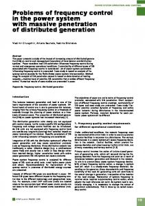
The numerical simulation was performed for five different speeds (66%, 72%, 76%, 80%, 90%). The simulation itself starts at stable operation conditions. While the shaft speed of the LPC and HPC were kept constant, the bypass-throttle was closed slowly in order to destabilize the LP compressor. Immediately prior a compressor surge occurs, air was injected in the simulation into the straight duct upstream of the first rotor. Resulting from the stabilization effect of the injected air the stable operating range of the compressor was extended. Fig. 7 clarifies the stabilization effect in form of the working map of the compressor. The right-hand solid line represents the measured surge line of the unaffected compressor. The left-hand solid line represents the surge line of the stabilized compressor (measurements) due to the injected air flow. The square symbols mark the calculated surge line predicted by the numerical simulation model with the application of the stabilization effect.
NUMERICAL SIMULATION Although the recent achievements in numerical simulation methods and computer hardware are tremendous, the simulation of a stalling compressor or even a stalling compressor stage is still a challenge and very time consuming. Saxer-Felici (1999) and Hah (1997) showed some unsteady Navier-Stokes simulation of a stalling stage indicating some of the physical processes involved during the stall of a stage. But these kinds of unsteady simulations are not applicable on a day-to-day basis during the design of a compressor or a stabilization device for a compression system. Therefore, a numerical simulation model of the aerothermodynamics of an aeroengine has been developed in order to analyze the unsteady and stable/unstable behavior of the air flow inside the engine during the whole operation range of the engine. E.g., the model is able to predict the time-depended pressure in each of the system components during the throttling of the engine. The model is capable to simulate the stable and unstable behavior of the engine. For the study presented here the model is used to study the stabilization effect of injected air flow in front of the first rotor of a Larzac 04 engine. The numerical model is based on the unsteady inviscid equations of fluid motion of compressible flow. The equations are solved numerically by the application of a time-accurate time step method. The spatial discretization is performed by an upwind discretization scheme based on flux filter matrices. A detailed description of the numerical methods used can be found at Breuer (1996). Each part of the engine system (blade row, stage, inter ducts, combustion chamber, nozzles, etc.) is described by its performance characteristic (pressure ratio / pressure loss vs. mass flow, basically). The unsteady response of a blade row to time-varying flow conditions is simulated by using a first-order lag function. The model of the Larzac 04 engine is separated into a straight duct in front of the LPC, the two stages of the LPC itself and a flow splitter. The latter divides the main flow into the bypass flow and the HPC core flow. The HP compressor is directly connected at the opposite end to a volume representing the combustion chamber (see Fig.6). Both, the bypass and the HPC core flow path is completed downstream by a variable throttle, respectively. The bypass throttle is used to control the operating point of the LP compressor. For a simplified model of the compression system it was not necessary to simulate engine components further downstream the combustion chamber, e.g. HP and LP turbine, exit nozzle, etc.
2.2 2.1
: no injection (measurement) : 5% injection (measurement) : 5% injection (calculated surge line)
2
90%
PILC
1.9 1.8 80%
1.7 1.6
76%
1.5
72% 66%
1.4 1.3 200
250
300 W2RED
350
400
Fig. 7: Extension of the operating range by air injection The 72% speed line shows the three differences between the non-affected compressor (lower circular symbol), a stabilized compressor with minimal air injection (upper circular symbol) and the predicted full stabilized compressor (square symbol). The good agreement of the numerically predicted and experimentally measured extension of the operating range of the compressor encourages the application of the numerical simulation model in order to design compressor stabilization devices based on air injection.
6
EXPERIMENTAL RESULTS General The investigation performed here represents the continuation of former investigations done by Leinhos et al. (2001) and others. In this research work for the first time the effects of constant air injection, the effects of a variation of the injection angle and the resulting influence on the performance data were analyzed. An experimental study of different control strategies also has been performed (Leinhos et al., 2002). In a further exploration done by Scheidler et al. (2003) the effects of inlet distortions together with active stabilization measures in a compression system have been examined. Also the consequences of air recirculation with respect to the stabilization feature and the appropriate performance results have been evaluated by the quoted authors. Based on the knowledge and experiences of those investigations the here presented study was carried out. Compared to the publication of Leinhos et al. (2002) an enhanced control software and control logic as well as an optimized air injection system has been applied in this investigation.
1.58
without air injection
1.56
3% constant air injection (nominal) 5% constant air injection (nominal) air injection, valves opening 35% constant air injection air injection with control
1.54
Π LPC
1.52 relative corrected spool speed n = 66%
1.5
θ
1.48 1.46 1.44 1.42 64%
1.4 200
225
250
W RED
275 [(kg*K0.5)/(s*bar)]
Fig. 9: Operating range profits due to control engagement at nθLPC = 66%
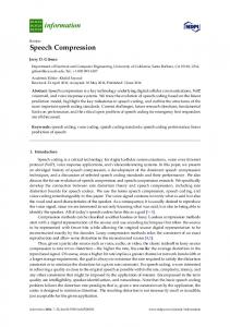
Rotating Stall Control at nθLPC = 66% Starting from a survey with constant air injection at nθLPC = 66% which also showed remarkable results with respect to former outcomes (see Fig. 8), the research work was concentrated on air injection with control. 1.58 witout air injection 3% constant air injection (nominal)
surge lines
1.56
5% constant air injection (nominal)
1.52
Π LPC
Fig. 10: Mass flow and total pressure value at the LPC exit at nθLPC = 66% with control engagement
constant air injection: valves opening 55% valves opening 40% valves opening 35% valves opening 30%
1.54
1.5
The very effective functionality of the control system has been proved by a test in which at constant air injection the LPC was throttled until a Rotating stall occurred and then the control system was switched on. Within a short period the control system was capable to recover the LPC from the Rotating stall and the total pressure at the LPC exit was restored (see Fig. 11).
relative corrected spool speed n = 66%
θ
1.48 1.46 1.44 steady state running line
1.42
64%
1.4
200
225
250
W RED
275 [(kg*K0.5)/(s*bar)]
Fig. 8: Operating range profits due to constant air injection at nθLPC = 66% Compared to the constant air injection the control engagement supplies some additional benefits with regard to the surge margin. Fig. 9 gives an impression of the additional gain in operating range. The opening rate of the valves has been continuously reduced to determine the lowest opening position at which the system can be restabilized with the control system engaged. As can be seen from Fig. 10, with a valve opening of 18% only a recurrence from Rotating stall is still possible. This corresponds to an average amount of air of around 400 g/s.
Fig. 11: Mass flow and total pressure value at the LPC exit at nθLPC = 66% with control engagement
7
Also the FFT analysis gives an evidence for the very successful adoption of the control inputs. The lapse of the time signal of the sensors in Fig. 12 gives a glimpse of the positive effect of the control algorithm. The reaction of valve no. 1 exemplary shows the quick reaction time and the successful recovery from Rotating stall is evidenced by the sensor signals. Even a re-occurrence of a Rotating stall cell due to a further throttling can be damped out by the control system within a few rotor revolutions.
Rotating Stall Control at nθLPC = 72% and nθLPC = 76% The examinations of the Rotating stall control at nθLPC = 72% resulted in the same achievements and conclusions as with the outcomes at nθLPC = 66% with regard to the compressor map and operating range benefits as well as with the stabilizing effects recognized in the mass flow diagrams and the different FFT analyses. Also the survey of the spool speed of nθLPC = 76% provided the same results. Control algorithm specific post treatment The former discussion was focused on the results of the system and the compressor. A control algorithm specific discussion of the experiments will be presented in this section. We will first start with a motivation for the specific shape of the stall controller. After this, an example for a procedure is shown, which consists in determining particularly the phase of the feedback signal. Besides the two test scenarios discussed above (recovery from a fully developed Rotating stall for a fixed operation point and delay of the onset of a Rotating stall when continuously throttling), this is a further example which shows the superiority of the controlled compared to a constant air injection. Due to the physical properties of a Rotating stall cell it seems natural, that the local blockage of the flow can be overcome by the injection of an additional amount of air, somehow "sparging" the blockage. As the plugging is only local, a constant injection over the whole circumference is certainly not the most efficient way of how to proceed. A local injection at the position of the Rotating stall cell seems to be more appropriate. This can only be done when using the information about the dynamic and circumferentially distributed pressure field at the compressor inlet (and thus the information about the position and the size of the Rotating stall cell) in a control algorithm, piloting the valves separately. As for the sparging of the blockage an additional to the mean mass flow and locally injected amount of air seems to be appropriate (and not a local reduction of the mean mass flow), only the positive parts of the generated feedback output signals of the controller are used for piloting the DDVs in this adapted and optimized version of the original algorithm used for the suppression of thermoacoustic instabilities. This means, that to the static mean position of the DDV only the positive components of the dynamic controller output signal is added. This particular shape can be seen in Fig. 12 in the plot on the right. Note, that this strategy is different from the one used successfully in the high speed range of the LPC, where the valves are piloted with the complete calculated signal, so the valves are not only dynamically opened with respect to the valve mean position, but also closed (these results are not subject of this publication and will not be discussed
Fig. 12: Time signal of sensors and valve no. 1 during a Rotating stall recovery at nθLPC = 66% A form of the Fourier Transformation Analysis, the Power Spectral Density (PSD), demonstrates the successful damping of the distortions responsible for the instability. In th the frequency spectrum of the 0 harmonic as well as in the st frequency spectrum of the 1 harmonic the accountable distortions at a rotor frequency (frot) of around 45% each are decreased by the controller’s input. It has to be mentioned that the distortion in the frequency spectrum of st the 1 harmonic is the responsible one which turns up again th in the signal of the 0 harmonic. This distortion in the th frequency spectrum of the 0 harmonic is of accompanying character and is not triggering the instability. Fig. 13 summarizes the described analyses.
th
st
Fig.: 13: PSD of 0 and 1 harmonic, at nθLPC = 66%
8
here). Due to the special character of the output signal for the stall control, the algorithm will be referred to as “onesided control”. A good indication for the benefit of an intelligent injection compared to a simple constant injection of additional air is the phase variation procedure. This is similar to a system identification, where the compressor, when running without injection, is operating in an unstable regime, i.e. a fully developed Rotating stall. Basically, a phase delay (and the appropriate gain) of the processed sensor signal that stabilizes the system has to be determined. The controller output is then converted and drives the power electronics, thus determining the movement of the DDVs around the static mean position. A successful injection of additional air will lead to a reduction of the sensor signal amplitude. This will be achieved if the injected air at the sensor position shows an opposite-phase characteristic with respect to the initially measured pressure. On the other hand, if the phase is wrong, a stabilization might not be possible (although additional air is injected), as the injected air does not superpose with the instability phenomenon in a destructive way. Fig. 14 shows the protocol of a phase variation procedure. On the top the waterfall plot features the devolution of the “worst case” sensor signal. The x-axis features the time evolution, the y-axis shows the frequency. The corresponding amplitude is specified by different colors, the physical values are given by the color bar. The blue curve in the middle plot shows the phase signal.
During its modification (from 0° to 180°/-180° respectively to 0° and further to 180°) a stabilization of the Rotating stall can be observed for a value of about –80°. Due to hysteresis effects the system remains stable even when the phase is changed further. Only when closing the valves (no additional air is injected; see the brown, upper curve in the lower plot for the average valve position), the Rotating stall reappears (also note the blue and cyan, lower curves in the lower plot, representing the long and short term RMS value of the sensor signals). When reopening the valves and switching on the controller with the wrong phase of 180°, the Rotating stall can not be eliminated. Only when changing the phase (this time from 180° crossing 0° down to –180° in order to approach the stabilizing phase region from the other direction; like this, the hysteresis effects can be eliminated), the controller manages to stabilize the Rotating stall again at around -80°. This result clearly shows the phase dependency of the feedback signal for a successful stabilization. Hence, the stabilization of a fully developed Rotating stall is not only a matter of the injected mass flow but significantly depends on the way how this is done. Note as well the different types of Rotating stall cells appearing during the documented experiment. In a first phase, a one cell Rotating stall can be observed (see the waterfall plot and the predominant unstable frequency of about 120Hz). Without injection, just behind the first stabilized area, a two cell Rotating stall establishes (with a predominant frequency of about 240Hz). After reopening again the valves with the wrong phase, the stall seems to change to a one cell stall.
Fig. 14: Identification Procedure
9
SUMMARY AND CONCLUSION Active stability control of the compression system in a twin-spool turbofan engine by air injection is a promising method to increase the available operating range, to achieve a higher loading of the compression system while gaining efficiency of the entire engine or to reduce the stage count within a compressor. Already constant air injection enables a considerable gain in surge margin. This allows to operate turbomachinery in a more efficient manner. The benefits of a control system to supervise any instabilities or their precursors by a frequency analysis have been demonstrated. The applied control system allows to lower the required mass flow of injected air to restabilize the compression system. In an improved attempt the Rotating stall control of a twin-spool turbofan engine has been evaluated for the lower and mid speed range up to nθLPC = 76%. Thus it is possible to operate the engine in this region at a higher loading while still keeping sufficient surge margin to avoid any critical situations. Different approaches and test cases have been analyzed to provide evidence for the functionality of the control system at different operational functions. While mainly perturbations st occurring in the 1 harmonic order play a dominant role with respect to the instability onset, they re-occur within th the signal of the 0 harmonic order with an accompanying effect. A numerical model has been successfully set up and further fitted to the experimental assembly. The results obtained by it are in good accordance with the experimental measured data. With regard to earlier investigations a modified Rotating stall controller has been adopted together with an improved air injection system. A comparison of constant air injection and air injection guided by the control system revealed the additional profit accomplished by the controller. Future investigations on this topic will deal with the speed range from nθLPC = 76% up to maximum power setting.
Freeman, C., Wilson, A., Day, I.J., Swinbanks, M.A., 1998: Experiments in Active Control of Stall on an Aeroengine Gas Turbine, ASME Journal of Turbomachinery, 120, pp. 637–647. Hah, Chunnil, 1997: Unsteady Aerodynamic Flow Phenomena in a Transonic Compressor Stage, Jour. of Propulsion and Power, Vol. 13, No. 3, May-June 1997, pp. 329-333. Hermann, J., Orthmann, A., Hoffmann, S., 1999: Active Instability Control of Combustion Oscillations in Heavy Duty Gas Turbines, 6th International Congress on Sound and Vibration, Copenhagen, Denmark. Herpel, Th., Fottner, L., 1993: A System for Monitoring, Measurement and Analysis of Transient Performance and Stall Phenomena of Gas Turbine Engines, ICIASF ´93 Record, IEEE Publication 93CH3199-7. Höss, B., Leinhos, D.C., Fottner, L., 2000: Stall Inception in the Compressor System of a Turbofan Engine, ASME J. of Turbomachinery, 122, pp. 32–44. Leinhos, D. C., Scheidler, S., Fottner, L., 2001: Active Stabilization of a Low Pressure Compressor in a Turbofan Engine with Constant Air Injection, AIAA 2001-3312, 37th AIAA/ASME/SAE/ASEE Joint Propulsion Conference and Exhibit, July 8-11, 2001, Salt Lake City, Utah. Leinhos, D. C., Scheidler, S., Fottner, L., Grauer, F., Hermann, J., Mettenleiter, M., Orthmann, A., 2002: Experiments in Active Stall Control of a Twin-Spool Turbofan Engine, ASME GT-2002-30002, Proceedings of ASME TURBO EXPO 2002, June 3-6, 2002, Amsterdam, The Netherlands.
ACKNOWLEDGEMENTS The research work done in this is study was supported by the Bavarian State Government (Bayerisches Luftfahrtforschungs- und Technologieprogramm) which is gratefully acknowledged. The authors are also indebted to company Moog, Germany for the kind contribution of valve hardware to the Universität der Bundeswehr München.
Nelson, E.B., Paduano, J.D., Epstein, A.H., 2000: Active Stabilization of Surge in an Axi-Centrifugal Turboshaft Engine, ASME Journal of Turbomachinery, 122, pp. 485–493. Saxer-Felici, H. M., Saxer, A. P., Inderbitzin, A., Gyarmathy, G., 1999: Prediction and Measurement of Rotating Stall Cells in an Axial Compressor, ASME Jour. of Turbomachinery, Vol. 121, 1999, pp. 365-375.
REFERENCES Breuer, Th., Servaty, S., 1996: Stall Inception and Surge in High-Speed Axial Flow Compressors, AGARD CP-571 26/1-17, 1996.
Scheidler, S.G., Fottner, L. (†), 2003: Active Stabilization of the Compression System in a Twin-spool Turbofan Engine at Inlet Distortions, ISABE-2003-1083, Proceedings of the XVI. International Symposium on Air Breathing Engines (ISABE), August 31 - September 5, 2003, Cleveland, Ohio.
Day, I.J., Breuer, T., Escuret, J., Cherrett, W., Wilson, A., 1999: Stall Inception and the Prospects for Active Control in Four High Speed Compressors, ASME J. of Turbomachinery, 121, pp.18–27.
10
Spakovszky, Z.S., Weigl, H.J., Paduano, J.D., van Schalkwyk, C.M., Suder, K.L., Bright, M.M., 1999: Rotating Stall Control in a High-Speed Stage with Inlet Distortion, Part I–Radial Distortion, ASME J. of Turbomachinery, 121, Part I: pp. 510-516, Part II–Circumferential Distortion, ibid., pp. 517–524. Weigl, H.J., Paduano, J.D., Fréchette, A.G., Epstein, A.H., Greitzer, E.M., Bright, M.M., Strazisar, A.J., 1998: Active Stabilization of Rotating Stall in a Transonic Single Stage Axial Compressor, ASME J. of Turbomachinery, 120, pp. 625–636.
11